


The simple answer is that you cannot derive any conclusions, unless you take extra steps beyond a typical scan.
Much like alginate or PVS impressions, it is impossible to tell if your impression is accurate before sending it off to the lab or pouring it up in your office. If the water to powder ratio is not right, if you removed the impression material before it properly set, or if you engaged undercuts with the material, you can easily distort the impression and introduce inaccuracies.
Most don’t recognize or appreciate this fact until the delivery of a restoration or a prosthesis. The same applies to digital impressions where one must understand the areas and reasons why they may introduce errors. The traditional methods used to validate or test the accuracy of an intra-oral scanner have absolutely no impact on any particular intra-oral scan. There are too many variables that cannot be accounted for, which range from the materials that are studied on a benchtop, to the simple fact that no investigator has access to the proprietary information used by companies that render models from digital scans.
To keep the topic simple, intra-oral scanners have a projector that shoots light onto an object and usually, two cameras offset at a specific angle, capture 30,40,50 or even more frames per second. The software algorithm then extrapolates those images into 3D models. There is great difficulty in assessing how each scanner and software manages translucent surfaces or reflective material because the calculations to render models are trade secrets and proprietary information. When you take all these matters into consideration, most of the literature on digital dentistry is irrelevant and does not apply to any particular clinical situation.
So how should a practitioner approach intra-oral scanning for best results?
S/He must understand the limitations of the particular scanner and the methodology that must be applied to the particular clinical situation. It is impractical to scan an edentulous person in the same manner one would scan fully dentate person. Black triangles in the gingival embrasures or a young patient with diastemas and mamelons can also introduce errors or distortions. The significant factors that impact the probability of accurate scans include:
- Translucent Enamel
- Highly Reflective Surfaces from Pre-Existing Restorations
- Long Spans of Edentulous Areas
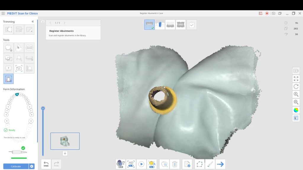
- Symmetric Objects (Scanbodies in Particular)
- Variable Focal Distances with Variances in Pitch, Roll, and Yaw
Translucent Enamel
The most likely area when s/he can introduce errors is in the anterior area where the incisor are not only narrower than molars but can also have translucent enamel. More importantly, when light hits glass / enamel it slows down and if it aimed from an angle, the light bends. Refraction of light is the primary reason for errors introduced in a model.

Here is a really boring video that explains what happens as it travels from one medium to another

Add just a little spacing between teeth with diastemas and you can quickly distort the accuracy of the model. This is true of ALL intra-oral scanners in the market. It is important to appreciate this because any study that extrapolates conclusions when scanning objects like stone models or typodont teeth are not just invalid, but also irresponsible on the part of the researcher. Here is a typical study that draws incorrect conclusions because in the material and methods section, they scanned stone models.

There are a few ways you can overcome these issues and the second video highlights some of our preferred methods. The concept is easy- block the light from travelling through the tooth structure and you are set! Watch the videos to learn how to do it
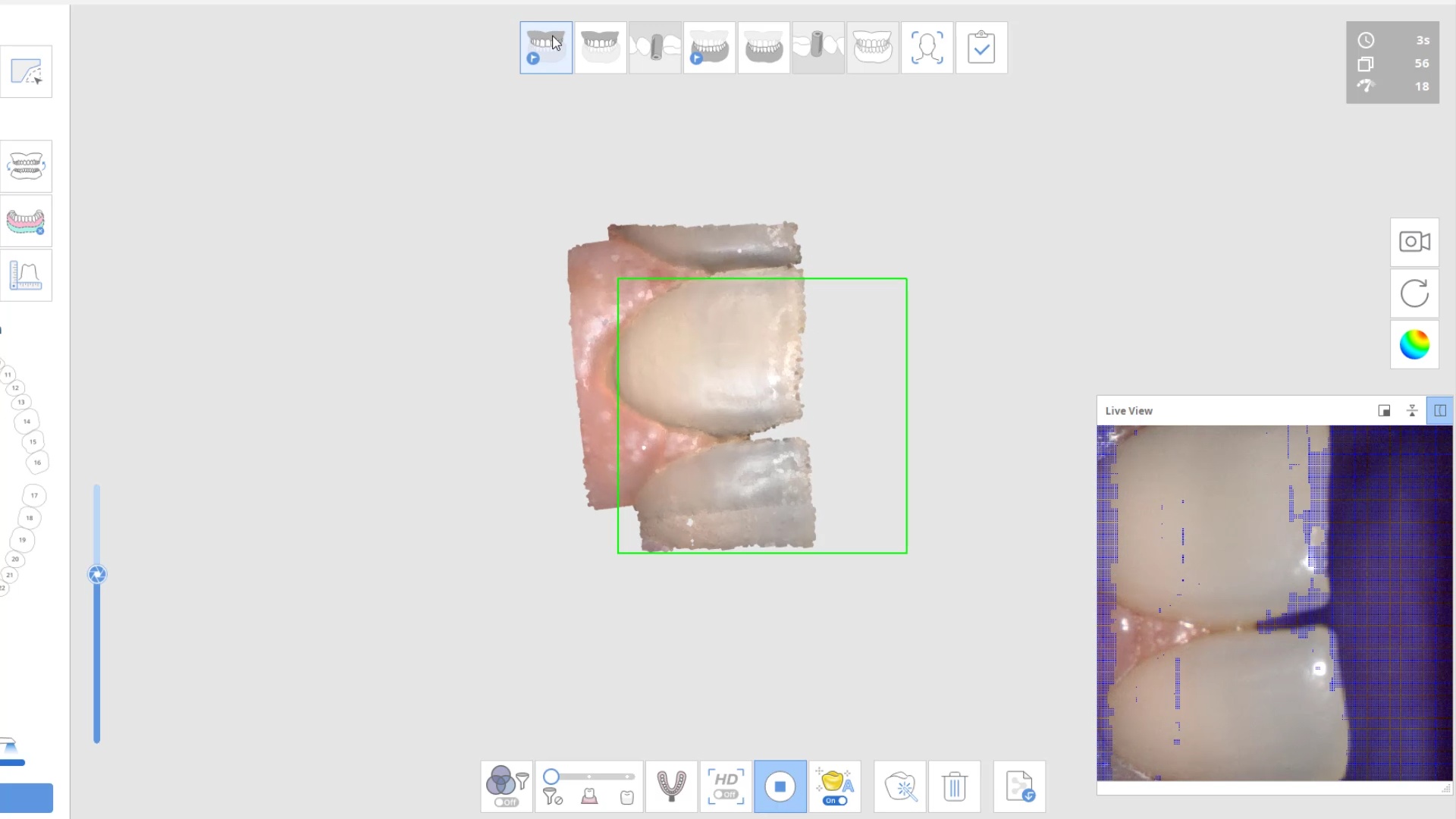
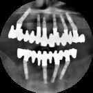
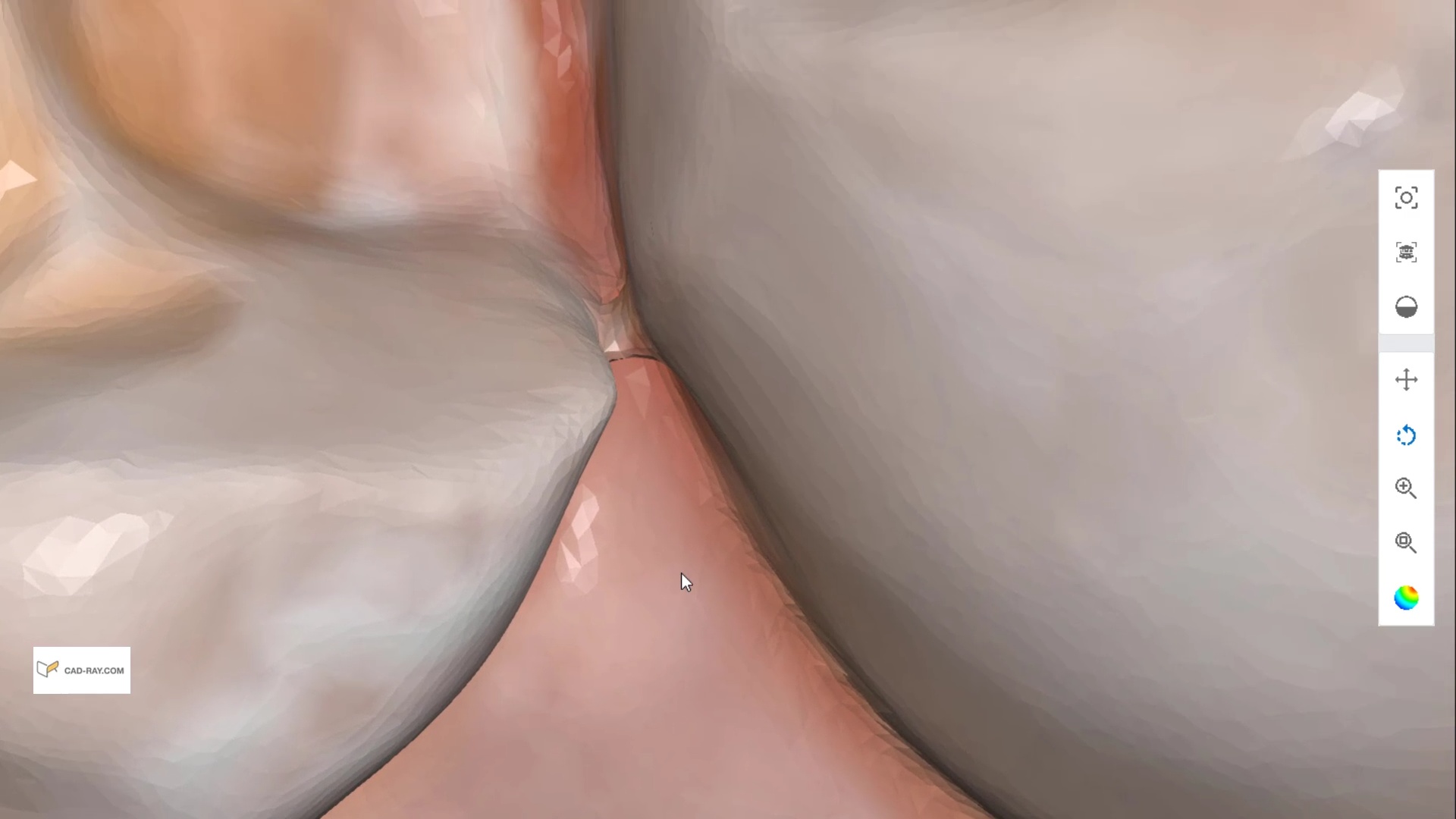
Here are some examples of how light shinning through the enamel and /or ceramic instead of bouncing back resulting in errors in model accuracy. Lesson #1 for every ios user is to know when and where they are likely to introduce error. in dentate cases, it usually is right that the transition from premolar to canine to lateral. The surface area decreases dramatically and if you have translucent enamel and / or material and / or highly reflective surfaces you can “derail” the model building. Here is an exaggerated demonstration
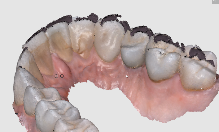
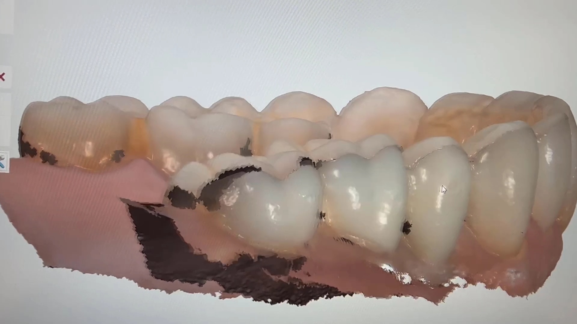
Translucent enamel can also play a role in distorting the cavosurface margins of a inlay or onlay restoration. When imaging from the occlusal, the gingiva below the margins acts as a barrier to block light transmission through the enamel, but as soon as you start to roll the camera to the buccal or lingual, and you have enamel with no substrate behind it to block light transmission, you can introduce errors in the equation with any scanner.
There are many ways to combat this which include powdering the tooth structure, using a rubber dam, or in Medit’s case, you can use the color subtraction filter. You selectively tell the scanner to ignore certain colors and you use that exact color (here, it is the color of the glove) to block light transmission through the enamel. So the software just ignores the blue, but the light is prevented from shining through reducing the errors you would introduce.
Highly Reflective Surfaces from Pre-Existing Restorations
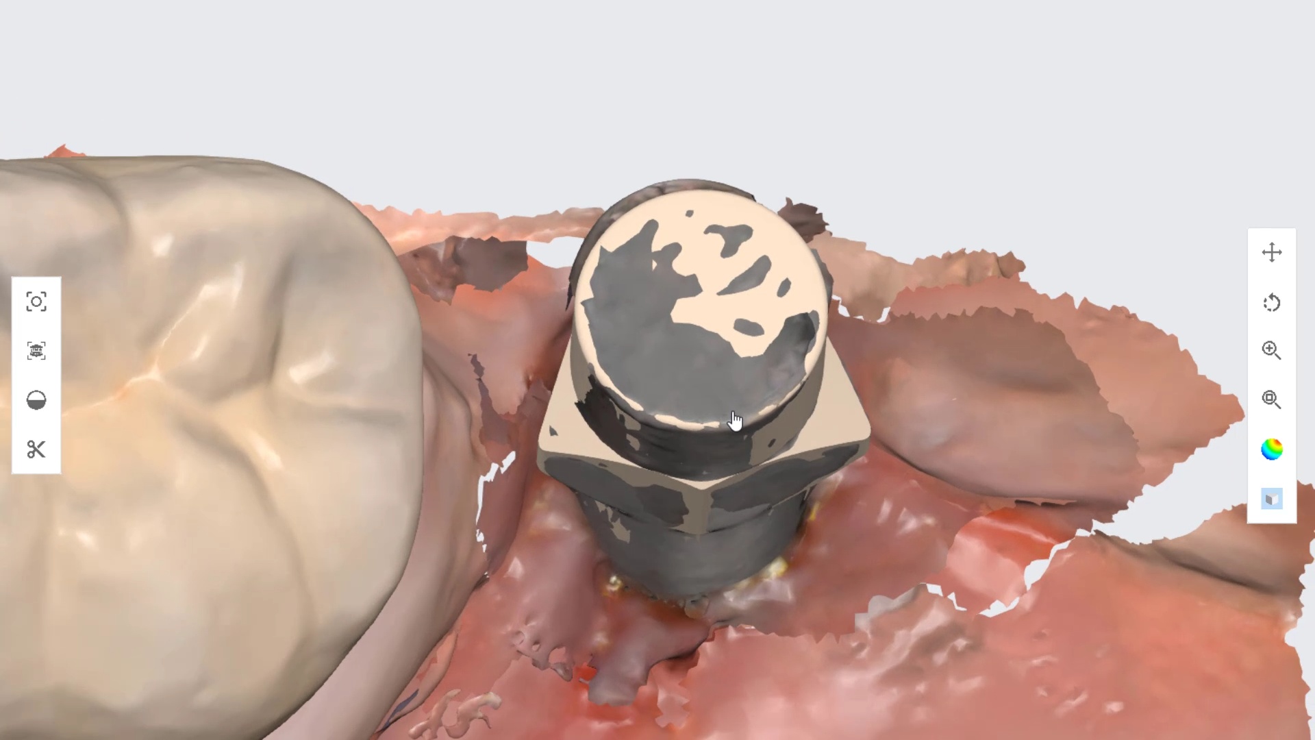
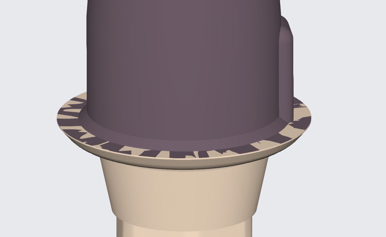
At the other end of the spectrum are reflective surfaces that can distort models. These include metal, zirconia, or lithium disilicate. This video is a good illustration of a titanium scanbody that was scanned and then the same shape in STL format was merged or overlayed on top of it. You can clearly visualize the distorted object which can have a significant impact on the end result if the user doesn’t recognize this detail.
For reference you can see how perfectly merged models look like by visualizing the digital shell that is overlayed on the tibase.
Long Edentulous Spans

You must be logged in to post a comment.