


How to Choose the Right SHINING 3D Denture Workflow
One of the most important decisions in the SHINING 3D denture workflow happens before design even begins: choosing the right case type.
For clinicians and labs, selecting the correct workflow helps protect esthetics, preserve function, and reduce remakes. For CAD-Ray customers, this is where efficient digital denture treatment begins.
In this guide, we break down when to use Natural Occlusion, Wax Rim, Old Denture, and Copy Denture inside the SHINING 3D workflow so you can choose the best path for each patient with confidence. This structure follows the workflow guidance in your source document.
Digital Denture Workflow Starts With the Right Reference
The best way to choose a workflow is to ask one simple question:
What is the most reliable reference I have for this patient’s bite, vertical dimension, and esthetics?
That answer will usually point you in the right direction.
If the natural dentition is still giving you a dependable bite reference, use it. If not, you may need a wax rim. If the patient already has a denture with useful clinical value, that existing prosthesis may become your best guide. And if they already love the denture they have, a copy workflow may be the easiest and most predictable choice.
1. When to Choose Natural Occlusion
For an immediate denture case, natural occlusion is often the best starting point because the patient’s existing teeth still provide a real-world reference for how the upper and lower arches come together. Your source notes that for immediate dentures, clinicians often select natural occlusion because the patient’s teeth preserve the original bite relationship and support a smoother transition.
Why Natural Occlusion Makes Sense
Natural occlusion is a strong choice when:
- The patient still has teeth in place before extraction
- The existing bite relationship is usable and clinically acceptable
- You want to preserve the patient’s familiar occlusion as much as possible
Key Benefits
Using natural occlusion can help:
- Maintain the patient’s original bite relationship
- Create a smoother transition into the immediate denture
- Support better immediate esthetics, function, and comfort
CAD-Ray Tip
If the existing dentition gives you a reliable bite reference, natural occlusion is usually the fastest and most predictable path for an immediate denture workflow.
2. When to Choose Wax Rim
Wax rim should be selected when the patient’s natural teeth can no longer be used to establish a trustworthy bite relationship. Your source specifically says to select wax rim when the patient is fully edentulous, when the existing bite is unreliable or needs to be changed, or when natural teeth cannot be used to determine occlusion.
Choose Wax Rim When
- The patient is fully edentulous
- The existing bite is unreliable
- The bite needs to be changed or re-established
- You cannot use natural teeth to determine occlusion
Why It Matters
Wax rim mode gives the clinician a clean way to establish the correct vertical dimension and jaw relationship when there is no dependable natural reference.
Best Use Case
This is the right choice for fully edentulous patients or any case where the current bite is too compromised to trust.
3. When to Choose Old Denture
Old Denture mode is ideal when the patient already has an existing denture that can serve as a reference for the new design. Your source says to use this option when the patient already has a denture you want to copy, improve, or use as a reference. It also notes that this is appropriate when the current denture has acceptable bite, acceptable vertical dimension, and decent esthetics.
Choose Old Denture When
- The patient has a current denture they are wearing
- That denture has an acceptable bite
- The vertical dimension is acceptable
- The esthetics are reasonably good
Why Clinicians Use This Mode
This workflow is especially useful when you want to:
- Duplicate the existing denture workflow
- Make a new denture similar to the current one
- Use the existing denture as a custom tray or design reference
CAD-Ray Tip
Old Denture mode is a great middle ground when the current prosthesis is not perfect enough to copy exactly, but still gives you a strong clinical foundation to build from.
4. When to Choose Copy Denture
Copy Denture should be used when the goal is simple: make the same denture again, just new. Your source says to use copy denture when you want to replicate an existing denture as closely as possible, especially when the patient is already happy with the bite, vertical dimension, tooth position, and esthetics.
Ideal Copy Denture Cases
This workflow is best when the patient:
- Already has a denture they are happy with overall
- Has a good bite
- Has an acceptable vertical dimension
- Likes the current tooth position and esthetics
Use Copy Denture When the Patient Needs
- A replacement for a worn, loose, or broken denture
- A spare or backup denture
In Plain English
Same denture. New version.
That is what Copy Denture is built for.

Quick Decision Guide
Use Natural Occlusion if:
- The patient still has teeth
- The existing bite is usable
- You are designing an immediate denture
Use Wax Rim if:
- The patient is fully edentulous
- The bite is unreliable or must be re-established
Use Old Denture if:
- The patient has an existing denture with useful clinical value
- You want to reference, improve, or build from it
Use Copy Denture if:
- The patient already loves their denture
- They just need a replacement or backup
Why Workflow Selection Matters
Choosing the correct SHINING 3D denture workflow is not just a software decision. It is a clinical decision that affects fit, function, esthetics, efficiency, and patient satisfaction.
At CAD-Ray, we believe better digital outcomes start with better clinical decision-making. When clinicians understand which workflow to choose and why, the entire process becomes faster, cleaner, and more predictable.
Final Takeaway
If you are unsure which path to take in SHINING 3D, start by asking:
What is the most reliable reference I have for this patient’s bite, vertical dimension, and esthetics?
When the teeth are reliable, use them.
When they are not, build the record another way.
When an old denture still holds value, reference it.
And when the patient already loves what they have, copy it.
Need Help With SHINING 3D Denture Workflows?
CAD-Ray helps dental teams implement digital workflows that are practical, profitable, and clinically sound. If you want help with SHINING 3D workflows, training, or workflow optimization, our team is here to help.
CAD-Ray
Digital dentistry training, support, and technology from real clinical humans.


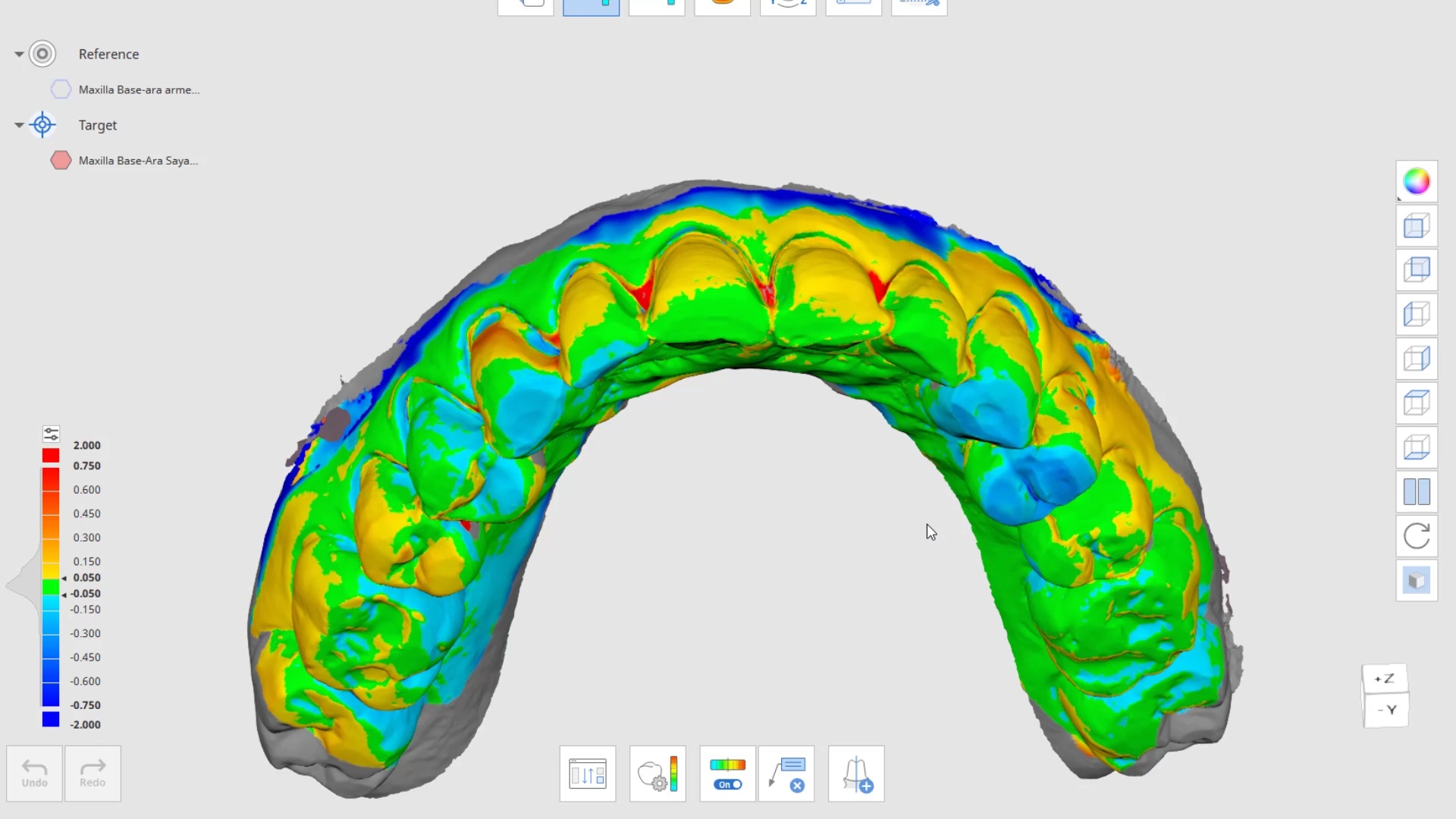
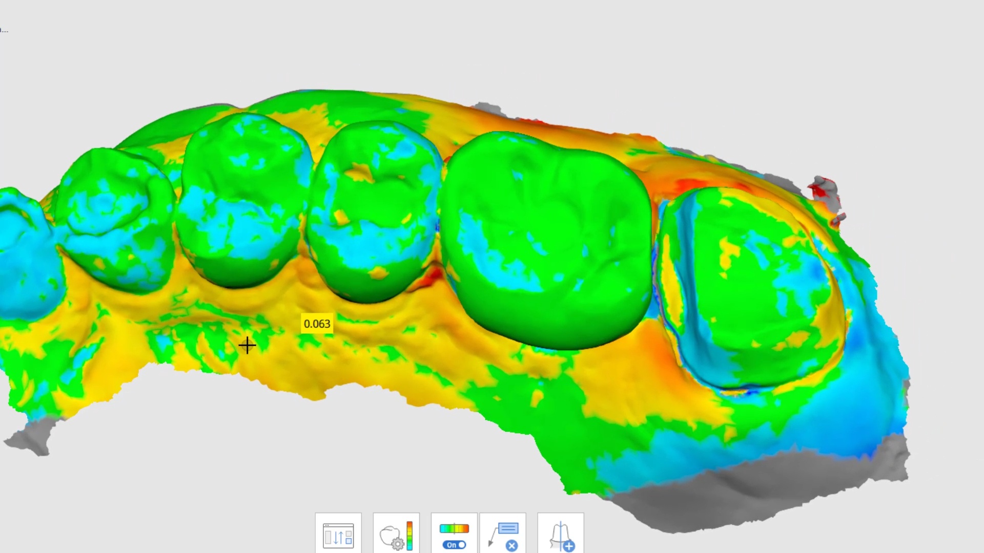
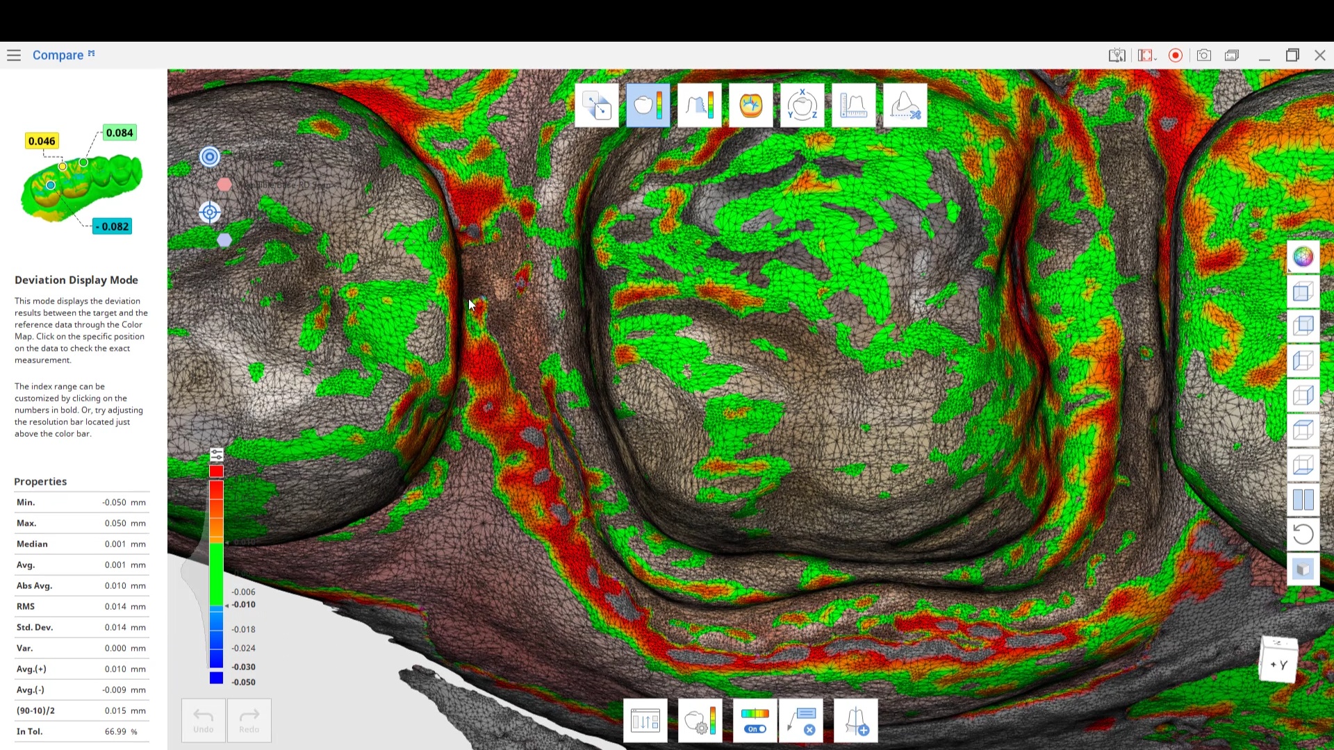
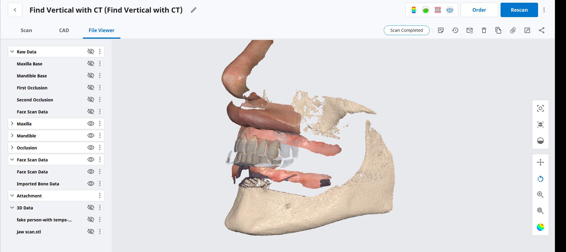
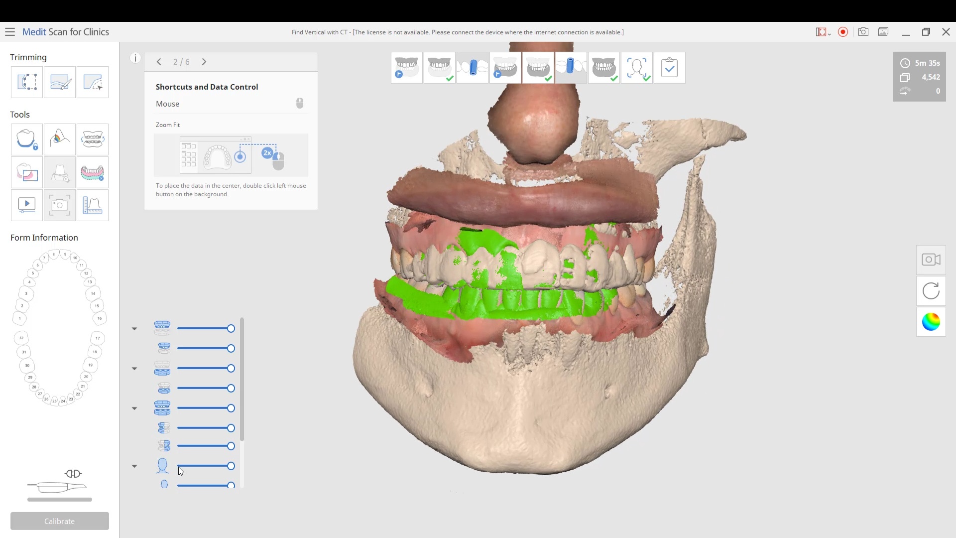
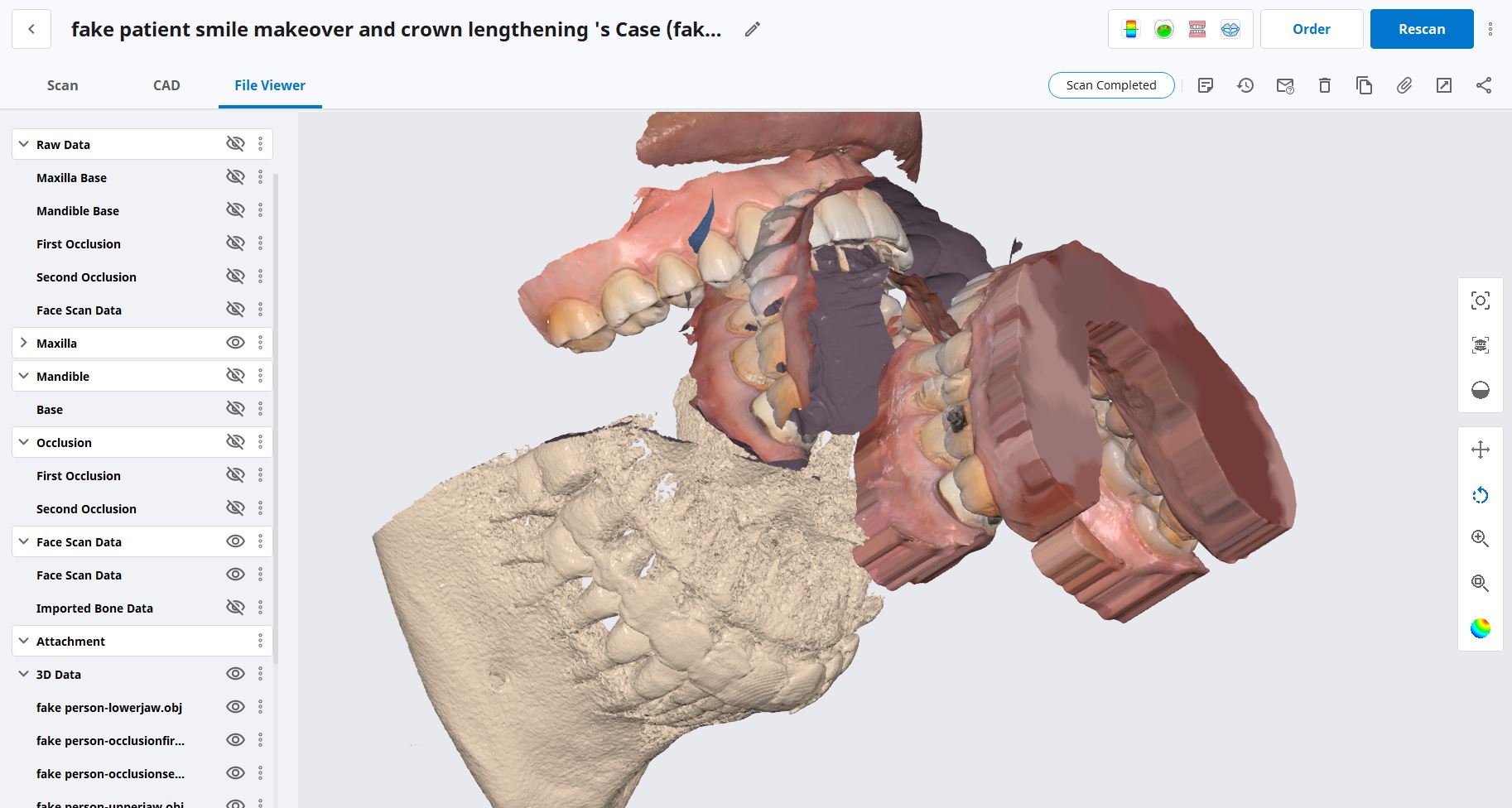
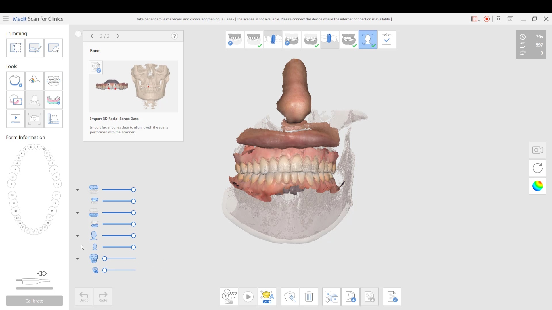
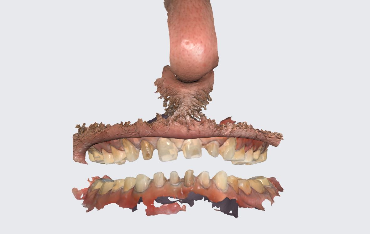 the patient was sedated and intubated for the case so we could not keep track of the bite. Instead, we imaged all 30 prepared teeth and used medit compare / design to digitally mount them to the wax ups. In the link provided you can download the models and relate them to each other […]