


CBCT Technology in Dentistry

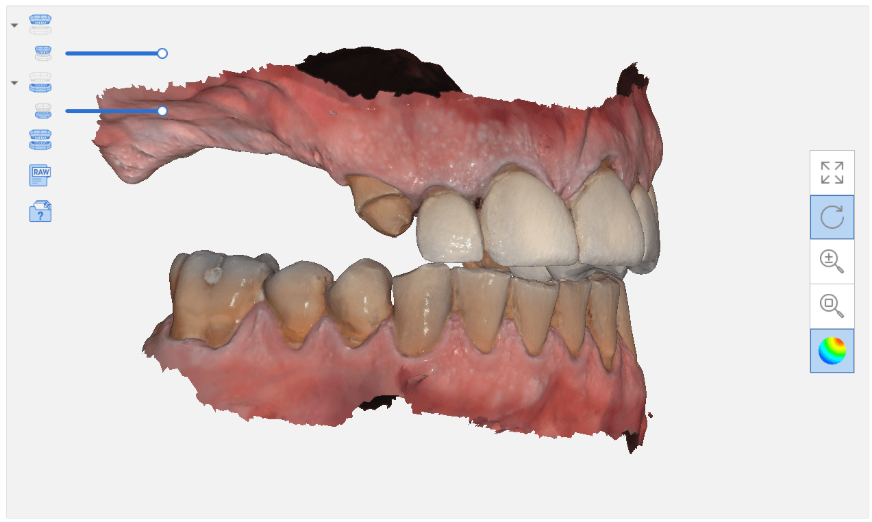
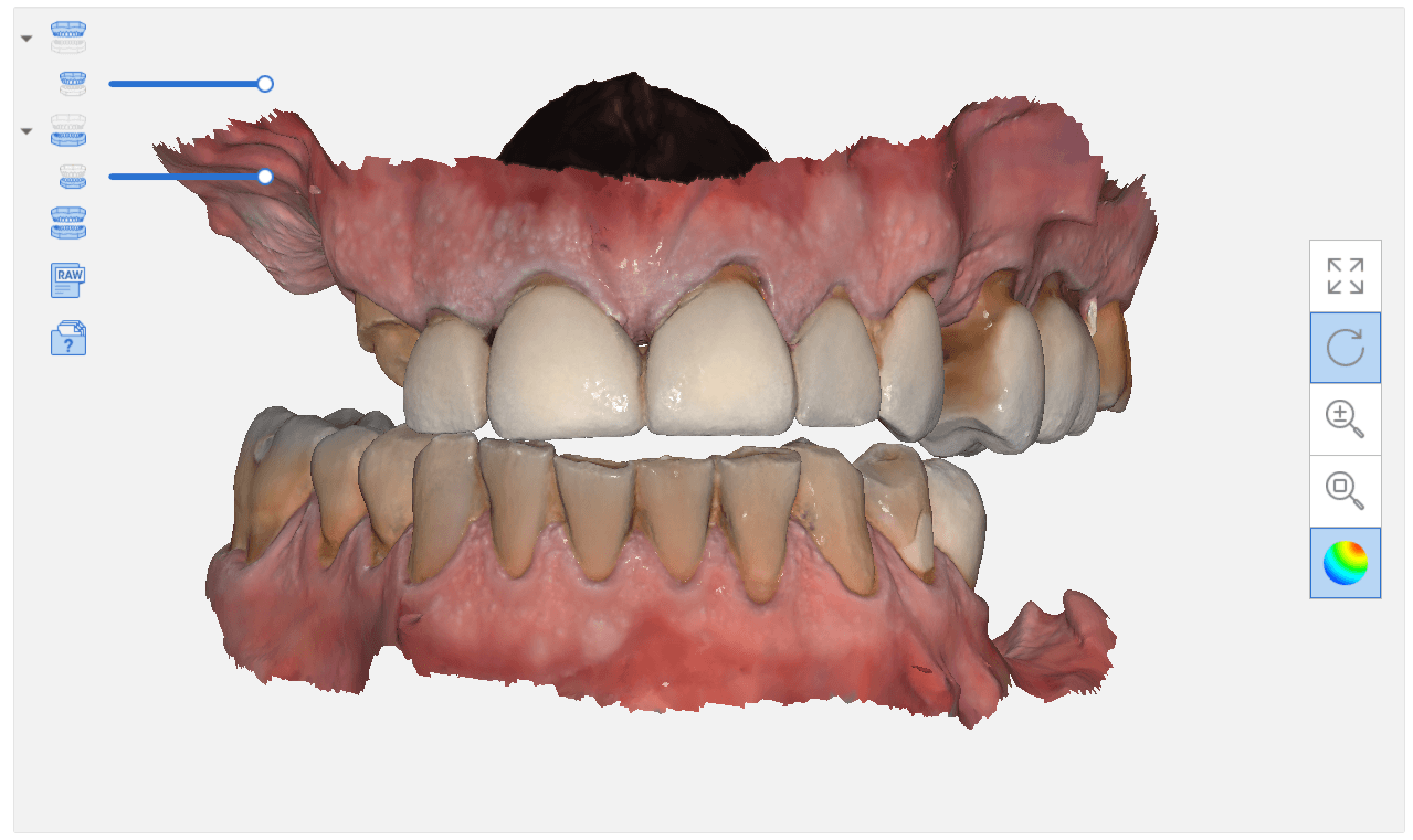
When you scan an upper arch and a lower arch with an intra-oral scanner and then export that case, usually the software places coordinates on the upper and lower models, so when you import them into another software, they properly articulate.
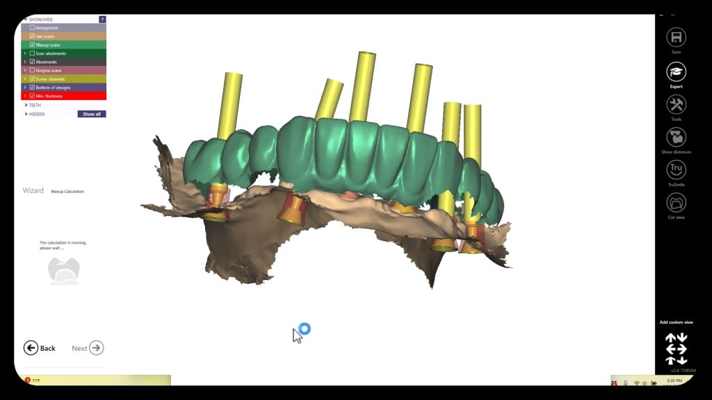
In this video, you can see how the upper arch is stitched to the CT image of the maxilla, an then how one can easily related the mandible stl file to articulate to the upper arch. This comes in handy in software like BlueSkyBio where you could add teeth to the equation and design implants so that they are prosthetically driven during the design phase.
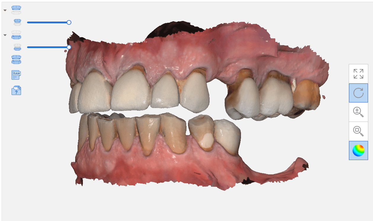
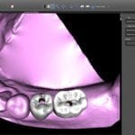
In this video, you can see how a quadrant of the lower arch and the upper arch can be imported into a third party software for design. Note that in this particular demonstration, there is not edentulous area and this video just demonstrates how you can place a digital tooth in your case and design the digital wax up to your liking. Advanced users generally just use the sleeve of the surgical stent to aid them in visualizing the occlusal table of the final prosthesis. A complete design lets you know where the contacts are and how much space you need to create the proper emergence profile.


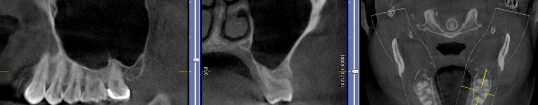
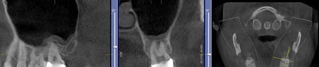
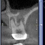
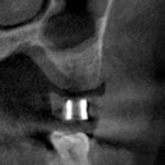
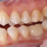
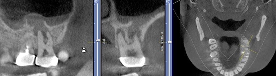
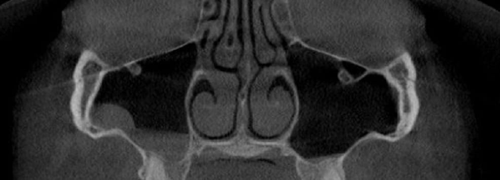
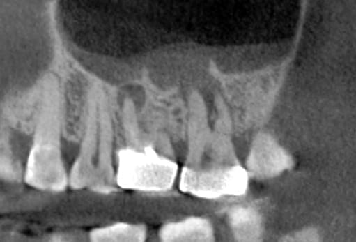
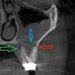
If you have had a CT in your practice long enough, you can start appreciating changes that happen on patients that you have scanned more than once in their lifetime. In this particular case, you can see how the preop scan shows an intact sinus floor, where as the second image, taken five years after the first one shows a periapical lesion and a perforation of the sinus floor. The patient was symptomatic and uncomfortable while biting on the second molar, but there were no other over signs of pulpal involvement. Also, if you are well versed in these matters, you can appreciate the inflammatory response, namely the opaque “cloud” right above the floor of the sinus. This is called Maxillary Sinusitis of Dental Origin MSDO
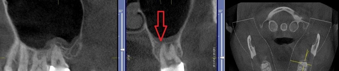
For a closer look, watch this video that walks you through the area of the perforation instead of just a single slice of an image. There is so much more information to be garnered when you “walk through” the slices

Join us for this very informative seminar that will you shape your future, as we teach you how to implement the top platforms that will help your practice grow in the next five years!
Dr. Armen Mirzayan, the founder of CAD-Ray Imaging, Implant Planning, and Stent Manufacturing Services will be conducting an event designed for CAD/CAM and/or Cone Beam users AND non-owners alike! By attending this seminar,

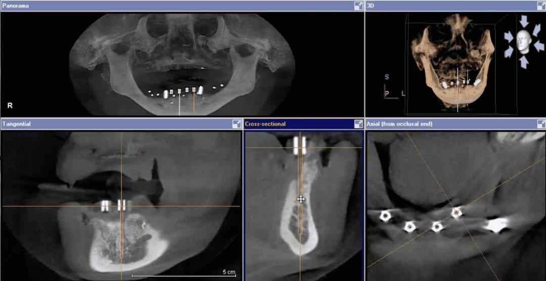
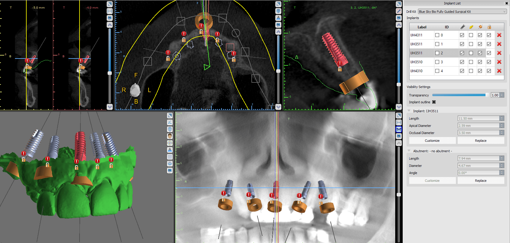
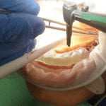
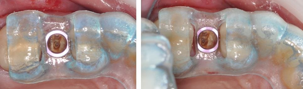
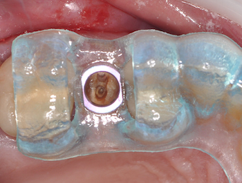
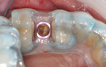
Larger cases, particularly edentulous cases, can inherently introduce errors and decrease accuracy. There are many reasons why this can happen, but generally, it revolves around human error. One thing we recommend at CAD-Ray is that you bring in the patient, seat the surgical stent, and take another CT scan. You can easily pick up error or more importantly, you can dramatically boost your confidence during the surgery that you are delivering very precise and accurate care.
[videopress rxWIzayq w=”1200″ hd=”true”]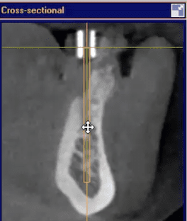 The video above is a quick demonstration of what you can visualize. You can even take a digital measuring tool and draw lines through the metal tube to verify that your path of draw for fixture placement is accurate. It is also important to make sure you have the surgical stent seated all the way and properly indexed. You can use the opposing dentition and have the patient bite down on cotton rolls during the scan to prevent the device from moving inadvertently.
We recommend you do this days before the proposed surgery, not the day of surgery, in case you need to make corrections.

This is probably the single most important thing to learn as a practicing clinician, who does not utilize a CT scanner. Posterior maxillary peri-apicals are generally useless as they do not convey the proper information due to overlap. It is impossible to see a perforation of the sinus floor with a PA. Moreover, patients are asymptomatic as it is draining so there is no chance of pressure build up in the maxillary antrum

Important facts about (Guided) Surgery, in no particular order:
1. The only way to replicate the 3D design during surgery is to use a fully guided stent. If you use a pilot stent, or if you get to your final osteotomy, and decide to remove the stent and place the implant freehand, you may veer off track. Implant systems such as Nobel Active are designed with aggressive cutting ends so that you can do this on purpose. You can easily get off track placing these types of implants free-hand.
2. There is a very specific way you must scan patients that are edentulous vs. partially edentulous. You must also scan heavily restored dentition differently than patients that do not have any radio-opaque fillings. This is detailed for you in the Remote Designs and Stents Section of our site, on the top navigation bar. Heavily restored dentition requires a scan with an appliance, and we need at least four to five teeth without metal / opacity to fabricate an accurate cad/cam derived stent.
 3. You cannot simply scan an edentulous patient, or a partially edentulous patient that is due to become completely edentulous, without proper planning and scanning protocols, if you want to do these cases guided.
For instance, if you look at this case to the left, we have no reference frame with regards to where the final prosthesis will be in relation to the final vertical dimension or the correct occlusal scheme. Also. if you notice, the distal teeth are not a reliable source of anchorage for the stents, so accurate surgery may not be attained.
Depending on experience and training level, we must take all these into consideration before designing the case for dental implants. You should also have a very good grasp of the costs associated with these cases when presenting to patients, otherwise the lab bills can surpass the amount of time you spend on these cases and the costs you accrue in unnecessary parts that you order for no reason.
4. The placement of the rings within the stent are very common issues that you must pay attention to. This is generally not an issue with molars, but edentulous spaces forward from those zone may sometimes be narrower than the rings themselves. There are a lot of solutions to this and we make sure you are aware of them. The easiest solution is to adjust the rings and the acrylic to make sure it is completely seated and not binding anywhere. But doing this can some times weaken the support and lead to stent fractures or displacement of the rings
5. ALWAYS plan with access during surgery in mind. A lot of systems cost well over 10,000$ and are clearly not designed by a clinician. it is imparrative to keep in mind that a little homework will save you a lot of grief and trouble. We are
[videopress GQLlnUww w=”1200″ hd=”true”]here to assist you with this important decision making process
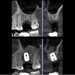
6. Never assume that a graft has healed properly. It may look great on an x-ray or a CT scan, but until you flap the area and visualize it, you really won’t know. This is a sample case with an immediate post op x-ray on the left, and a one week post op where the patient had an infection and swelling from the graft breaking apart.


7.  Many people believe that guided surgery means that you have “tissue punch”. Although this is less traumatic to the patient, it can sometimes lead to issues that can cause the implant to fail. If the tissue does not completely heal over the healing abutments or cover screws, a peri-coronitis type of phenomon can occur.
Think of it as an operculum that gets infected.This can lead to undesired bone loss around the top of the implant. If intervened early enough, the area can be debrided or cleaned with a soft tissue laser and a tall collar can keep the tissue away. A tall collar on the other hand, if placed too soon, may have its owns consequences. The patient can inadvertantly bite into an abutment which can lead to failure. Most clinicians prefer to flap the area, place the fixture and a cover screw, then close the flap
8. The ring in the sleeve MAY pop out during surgery. Make sure to properly protect the patient’s airway at all times during surgery. If the rings comes out, simply re-inserted into the stent and proceed with surgery. A lot of people actually prefer to be able to easily remove the ring, sterilize it, and use it for other matters
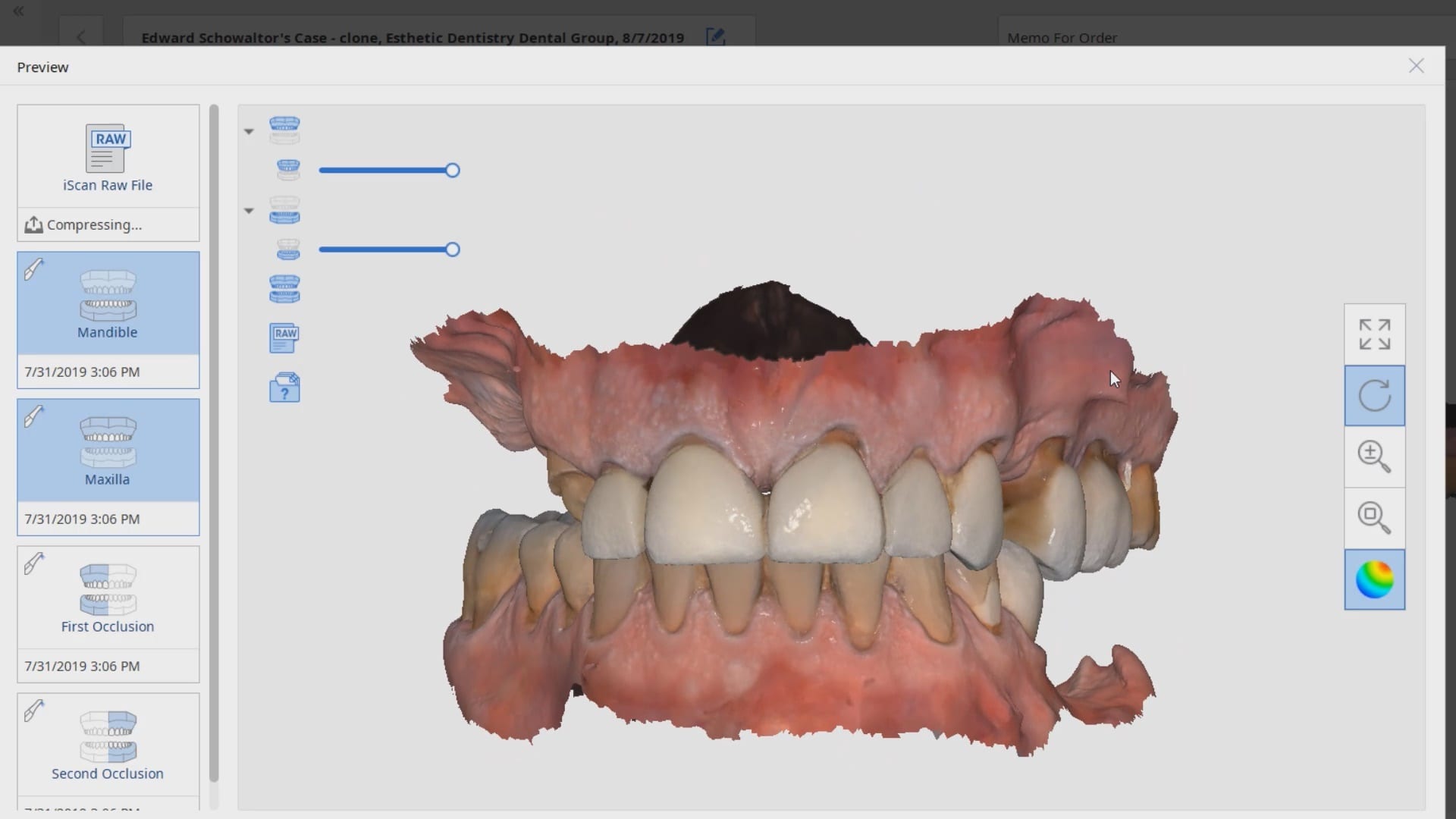
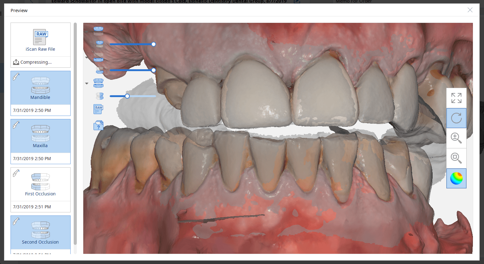
9. When scanning a patient for implant reasons, make sure opposing dentistion are not touching each other in tooth borne cases. It is very difficult to design a case when the teeth are overlapping. For orthodontic scans, make sure the patient is biting all the way
10. The carrier for the implant sometimes mechanicallt locks to the internal of a fixture. When trying to disassemle the complex, you may inadvertantly spin the implant counterclockwise, losing your primary stability. There are east remedies for this if you anticipate it well.
[videopress rIP2PDGa w=”1200″ hd=”true”]11. There are a few reasons why your implant may not reach its final postion when using guided surgery. Assuming all the proper protocols were followed, the two main likley reasons are that you may have not confirmed that you fully drilled to depth and did not bottom out the drills. The other reason may be becuase your carrier bumped into bone and did not allow you to seat all the way. Most carriers are wider than the implant or the ostetomy placed.
12. Make sure you double check the plan and consider confirming the exact drills that are to be used with your assitant. When multiple implants are involved, consider placing the one with that is going to be placed deeper or use the longest drill in the equation. Once that is done, place the drill as far away from your reach so that you do not inadvertantly use it for the next osteotomy
13. Most guided cases are short in duration. Consider using anesthetic without epinephrine; blood flow is good for the wound! When using a blade to make an incision avoid placing it on the crest of the ridge so you don’t have to manage two flaps, and when you seat the stent, make sure you don’t crush the tissue and occlude blood flow. The following information was submitted by a colleague, Dr. James Tom
Using local anesthesia for CT guided implant surgery- Dr. James Tom (Clinical Associate Professor, Director CHAMP+ Anesthesiology, Dental Anesthesiology Service, Ostrow School of Dentistry)
“Using local anesthesia for CT guided implant surgery Practitioners wanting to preserve blood flow to the surgical implant site and provide a short duration of local anesthesia are practically limited to two commercially available “plain” (non-epiephrine containing) dental anesthetics. Of the two available in the United States, prilocaine 4% solution (Citanest Plain – Dentsply) or mepivicaine plain (Polocaine – Dentsply, Carbocaine – Cook-Waite, or Scandonest – Septodont) generally provide anywhere from 20-25 minutes of pulpal anesthesia, respectively, or between 105 and 90 minutes of soft-tissue anesthesia. When these two anesthetic solutions are employed in infiltration techniques as described by Heller and Shankland in 2001 (Heller AA & Shankland WE. 2001 . Alternative to the Mandibular Block Anesthesia When Placing Mandibular Implants Posterior to the Mental Foramen. Journal of Implantology. 127-133), the incidence of inferior alveolar paresthesia can be reduced. Leaving out the commonly used vasoconstrictor epinephrine will also encourage the vasodilative properties of amide local anesthetics.”
14. you will likely need drill extenders to keep from bumping into stents in certain situations
[videopress 1cLsZEcy w=”1200″ hd=”true”]
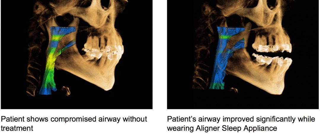
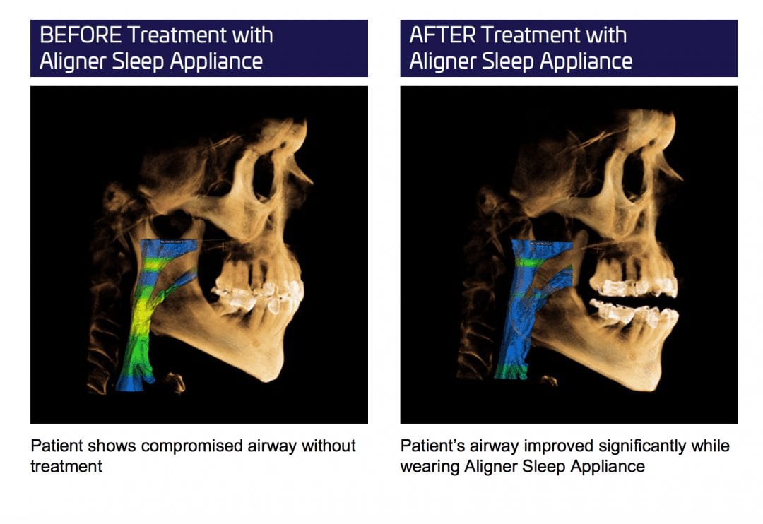
Another appliance company for apnea. I believe its over 150 of them now. This one promoted at invisalign summit. I have no issues with the appliances. 300 would be even better, but what drives me nuts is when companies and shills show this before and after on CT’s and how the airway opens after treatment. It is absolutely fraudulent to make such claims and to measure success in this manner. It is very misleading and can get a lot of people in a lot of trouble.
I’m a big fan of CT scans. I don’t even take fmx any more. It’s CT and bitewings most of the time. Periapical in posterior maxilla is useless to me. But this non-sense has to stop. It starts with donut face stuffing fatsos making up conditions that don’t exist and that it perpetuates through the industry as the rest try and catch up. next thing you know everyone is claiming success with their device by showing before and after CT scans as their measured form of success.
Patient positioning can have an impact on this airway measurement. Tongue positioning does too. Swallowing can. So many factors in a 15 second scan can contribute to it as well.
let me make it simple for every dentist here to understand this: NO ONE can claim that the airway improved with sleep appliance therapy based on the measurement of airway difference between pre and post op CT’s. It is absolute fraud, dangerous, and it falls under the federal false claims act.

Watch this video that walks you through the tip of the nose and then through the nasal passages. Although never diagnostic, we can become suspicious that air traveling through such a narrow space must meet a lot of resistance. Remember, every time you decrease the diameter by half, you increase the resistance to flow sixteen fold
[videopress 00N1DqQu]

There are multiple reasons to invest in CBCT technology for dentistry. The current top 3 reasons are for diagnosis, implantology, and sleep apnea.

This article will demystify the purchase decision making process and help you with implementation of the technology. It will remain neutral with regards to the machine and manufacturer type and will highlight / define the clinical relevance for each topic. Having the vision for future practice growth will also play a large part in what type of machine you will purchase.
Generally the field of view determines the cost of the machine. There are very valid arguments on either side: restrict the area imaged for very specific clinic needs vs. capturing as much information from both jaws, the condyles, the nasal passages and at least the complete outline of the maxillary sinus as part of your comprehensive exam. Each clinician must decide whether the added exposure to the radiation is worth the risk.
Small fields of view machines essentially eliminate the capability to do guided surgery. The trend over the last 5 years as been to not only assess the bone volume with CT scans but to also utilize the data to derive a three dimensional plan that can be used to fabricate a surgical stent to deliver a fixture in the exact same position of the three dimensional design.
With a limited field of view that shows one or two teeth to the targeted area, you essential opt out of the capability of performing this type of procedure for a variety of reasons. Although one can manipulate multiple images and create a larger model to work with utilizing specific software, it is not worth the effort. To keep it simple, if you plan on placing implants, the field of view should contain the complete image of the Maxilla and the Mandible. You can choose a machine that does not capture the condyles, but ideally, the field should allow you to capture the third molars with each image taken, as this can become part of your regular examination.
Oftentimes with smaller machines, parts of the root tips of the wisdom teeth are “cone cut”, so you have to re-position the patient and scan them again to visualize the data you are scanning for, exposing them to more radiation unnecessarily. The next level for the field of view that you should consider should capture the condyles and all of the maxillary sinus.
The position of the condyle and a radiologist’s report can be great documentation for large restorative cases. Generally, most doctors submit for a pathology report to make sure there is no disease process and then submit another scan after the new vertical dimension is established to catalog the change in condylar position. The sinus and its relationship with posterior maxillary teeth will likely be the most surprising aspect of CBCT for most dentists, as perforations through the path of least resistance, the floor if the sinus, are not ever visible with peri-apicals.

Furthermore, the vast majority of sinus issues that remain unresolved AFTER intervention by ENT’s are odonotogenic in origin. A large field view will allow you to see the maxillary sinus in its entirety, depicting the drainage and patency of the ostium.
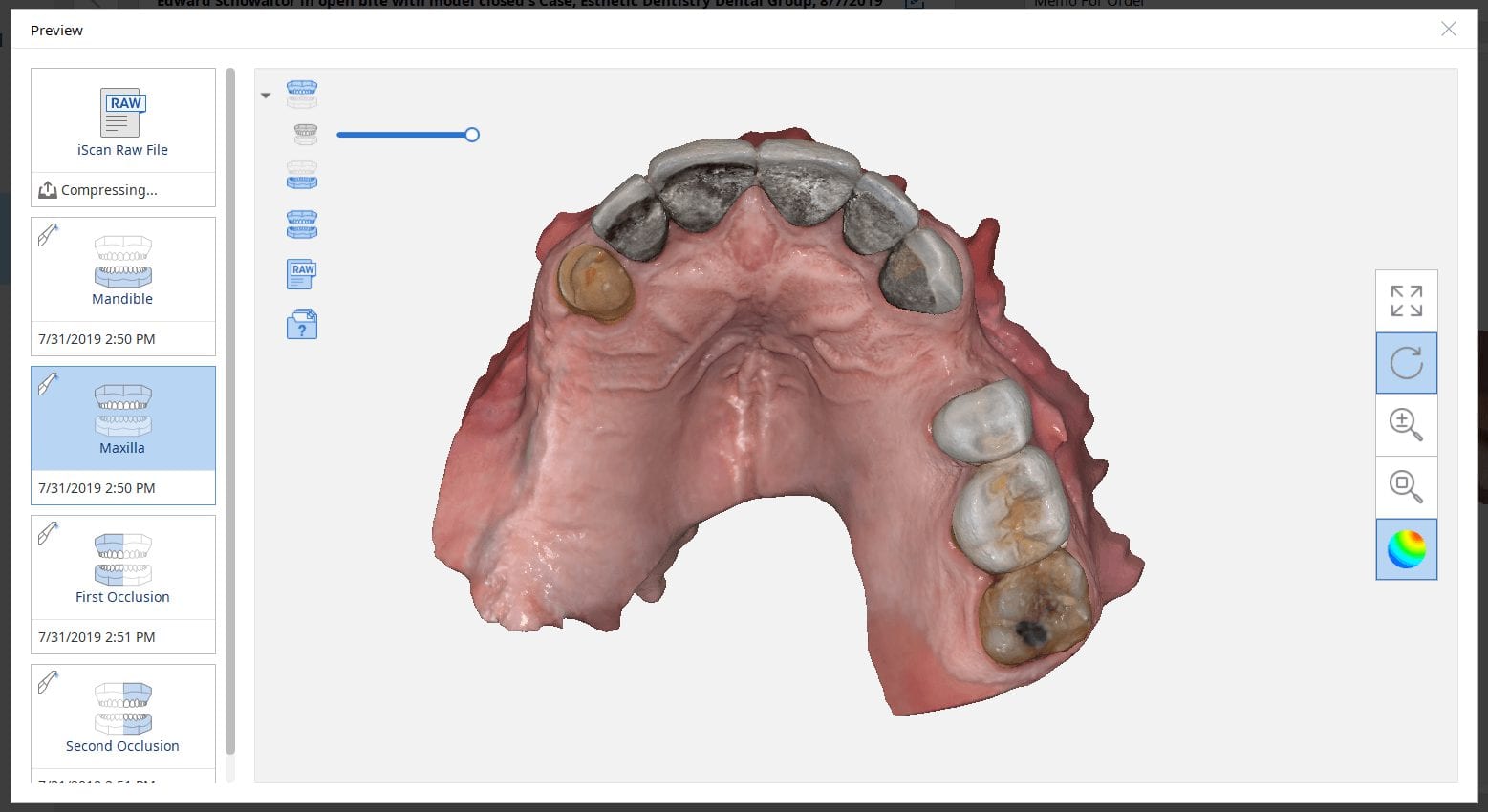
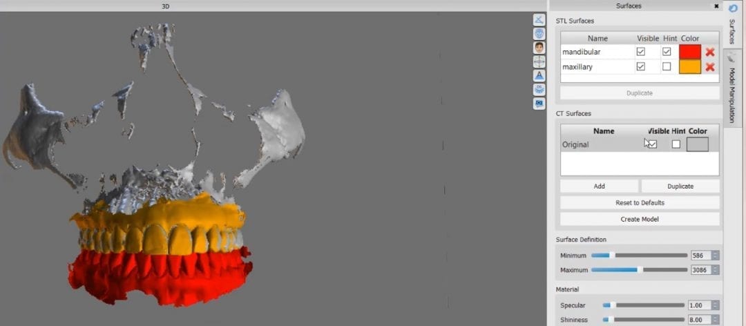
Another important element to consider is artifact and scatter. All cone beam machines produce artifact around opaque materials as see in the image to the right. This effect is very important to control in implant planning. There are numerous workarounds that include incorporating more dentition in the equation that are not heavily restored with radio-opaque material. As a last resort, one can use a scan appliance to overcome the inaccuracies introduced by this artifact.
Indications of risk for Obstructive Sleep-disordered breathing seen on Cone Beam Computed Tomography
Patient information regarding the presence of sleep disordered breathing (apnea), begins with thorough clinical evaluation. The patient/parent should be interviewed regarding snoring, mouth breathing, medications, and visits to the ENT. An important initial area of assessment includes facial profile (as Class II dolicofacial profiles tend to have more airway problems than other facial types). Resting lip posture, droopy eyes, and the presence of “shiners” (vascular congestion manifested as darkness under the eyes) should be noted. Intraoral findings, such as high palatal vault, narrowed transverse dimensions of the maxillary and/or mandibular dentition, anterior or posterior crossbites with associated functional shifts can be related to airway irregularities.
Once the above questions and clinical assessment are performed, and the findings suggest presence of breathing disorder, imaging is useful to identify possible anatomic and morphologic structures that contribute to risk for presence or development of obstructive sleep-disordered breathing. While sleep apnea is not diagnosed with imaging, cone beam computed tomography (CBCT) exams are valuable in providing three-dimensional or multiplanar views that enable clear definition of irregularities that may be creating obstruction or resistance to airflow through the nasal passages, the nasopharynx, the oropharynx, and the hypopharynx. Some of these irregularities include soft-tissue enlargements or aberrant morphology, bony structures, dental findings, cephalometric measurements, and pathology. Examples in these categories are depicted in images below.
Commonly seen irregularities that indicate risk for presence or development of obstructive sleep-disordered breathing
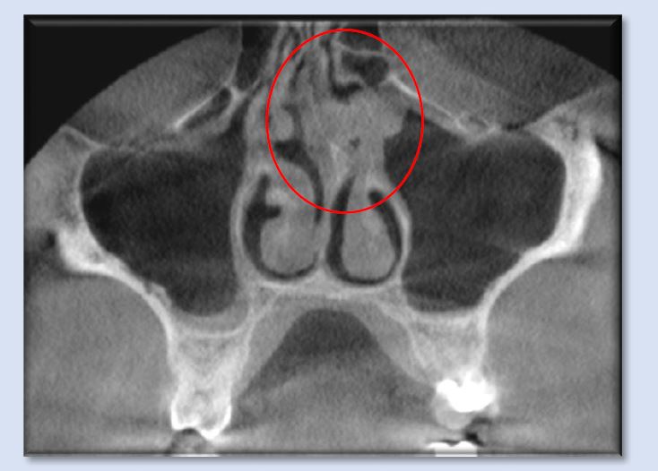
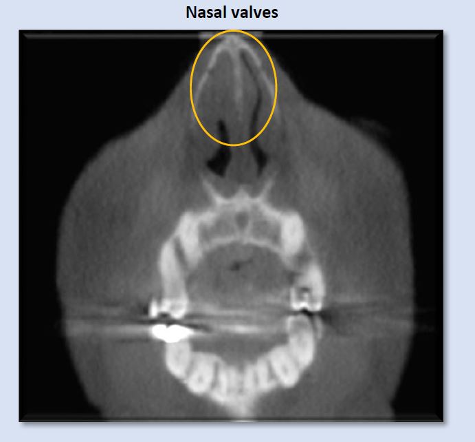 Airflow into the patient’s airway begins at the external, then the internal, nasal valves. These entrances are composed of cartilage, muscle, ligaments, and mucosal soft-tissue, all of which can display irregularities of various etiologies, creating narrowing or blockages. The image above depicts narrowed left internal nasal valve, and constricted right internal nasal valve.
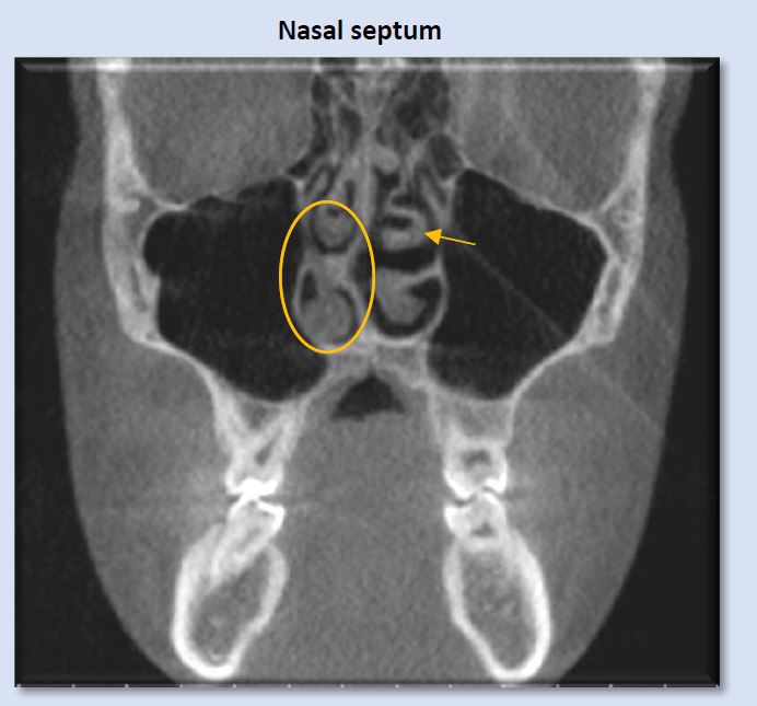
Deviation of the nasal septum is a frequent finding. A large range of variability is seen. Some examples include minor deviation of the full septum, deviation of a small segment, enlarged septal tubercle, formation of a septal spur, and S-shaped contour that deviates both to the right and the left at different levels of the septum. The image above shows right deviation near the level of the right middle meatus, with a bulbous morphology of the septal tubercle contacting the right inferior concha. This can introduce alteration to airflow pattern through the nasal passage.

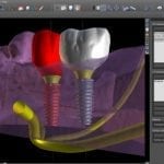
One of the greatest a clinician can learn is to master implant restorations by being involved in the planning and treatment of the case. Very quickly, you can realize how the exact placement of the fixture will determine your clinical outcome. Giving yourself enough running room to create the emergence profile is critical. Watch this video that explains where to place the implant so you can create natural looking restorations


Patient information regarding the presence of sleep disordered breathing (apnea), begins with thorough clinical evaluation. The patient/parent should be interviewed regarding snoring, mouth breathing, medications, and visits to the ENT. An important initial area of assessment includes facial profile (as Class II dolicofacial profiles tend to have more airway problems than other facial types). Resting lip posture, droopy eyes, and the presence of “shiners” (vascular congestion manifested as darkness under the eyes) should be noted. Intraoral findings, such as high palatal vault, narrowed transverse dimensions of the maxillary and/or mandibular dentition, anterior or posterior crossbites with associated functional shifts can be related to airway irregularities.
Once the above questions and clinical assessment are performed, and the findings suggest presence of breathing disorder, imaging is useful to identify possible anatomic and morphologic structures that contribute to risk for presence or development of obstructive sleep-disordered breathing. While sleep apnea is not diagnosed with imaging, cone beam computed tomography (CBCT) exams are valuable in providing three-dimensional or multiplanar views that enable clear definition of irregularities that may be creating obstruction or resistance to airflow through the nasal passages, the nasopharynx, the oropharynx, and the hypopharynx. Some of these irregularities include soft-tissue enlargements or aberrant morphology, bony structures, dental findings, cephalometric measurements, and pathology. Examples in these categories are depicted in images below.
Commonly seen irregularities that indicate risk for presence or development of obstructive sleep-disordered breathing
Airflow into the patient’s airway begins at the external, then the internal, nasal valves. These entrances are composed of cartilage, muscle, ligaments, and mucosal soft-tissue, all of which can display irregularities of various etiologies, creating narrowing or blockages. The image above depicts narrowed left internal nasal valve, and constricted right internal nasal valve.
Deviation of the nasal septum is a frequent finding. A large range of variability is seen. Some examples include minor deviation of the full septum, deviation of a small segment, enlarged septal tubercle, formation of a septal spur, and S-shaped contour that deviates both to the right and the left at different levels of the septum. The image above shows right deviation near the level of the right middle meatus, with a bulbous morphology of the septal tubercle contacting the right inferior concha. This can introduce alteration to airflow pattern through the nasal passage.
Note: an anatomic variant of paradoxical turbinate (arrow) is present at the left middle concha. This finding is often without clinical significance, but can create a blockage of the ipsilateral ostiomeatal complex. In this case, the left ostiomeatal complex is patent.
The above image shows septal tubercle/spur formation to the left, where it contacts the superior portion of the left inferior concha and the left middle concha. More superiorly, the nasal septum displays a gradual curvature toward the right. Accompanying these deviations is mild soft-tissue enlargement of the nasal septum as well as mucosal thickening in the superior portion of the left maxillary sinus. The combination of these features is forming obstruction to airflow through the nasal cavity and creating obstruction of the left ostiomeatal complex.
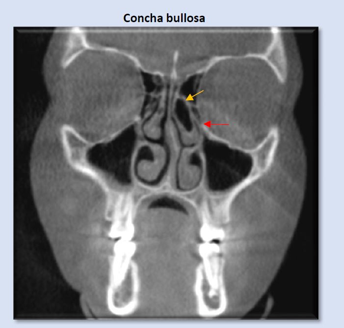
Concha bullosa is an air cell which is most commonly seen occupying the middle concha, either unilaterally or bilaterally. On occasion, smaller conchae bullosa are seen at the superior conchae. They are frequently clinically insignificant, but can influence deviation of the nasal septum and create narrowing or blockage of the ostiomeatal unit. The image above shows an obstructed left ostiomeatal complex (red arrow).
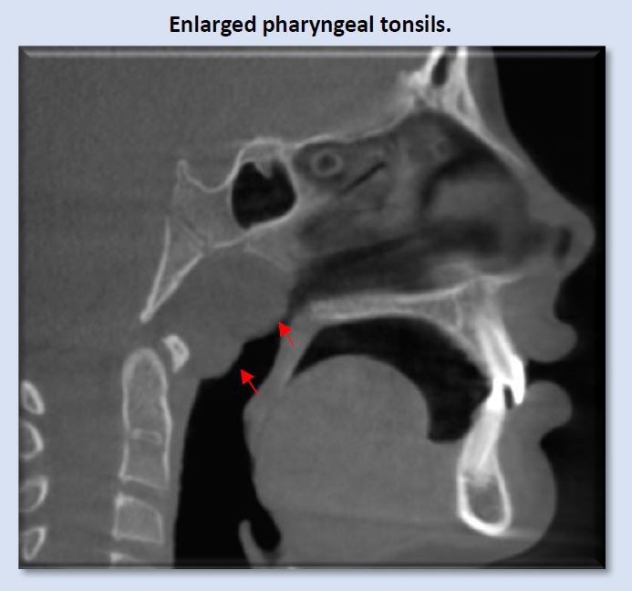
Enlargement of the pharyngeal tonsils (adenoids) is commonly seen, most often in children, which would be expected. If enlargement is seen in adults, more questions regarding etiology are raised, as these tissues typically begin gradual regression after the age of 12. This size enlargement creates significant blockage in the nasopharynx. Note parted lips, even though the condition of deep anterior vertical overlap is present.
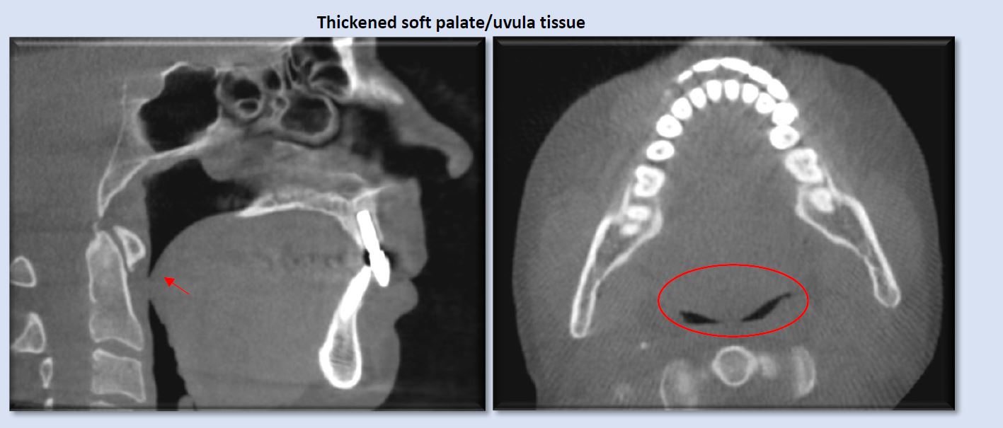
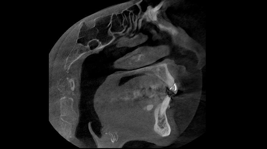
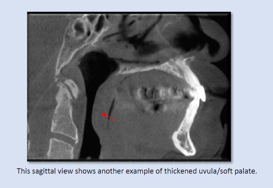
Thickened soft palate and uvula soft-tissue can narrow, and at times, constrict the airway, even while the patient is in an upright position. The presence of obstructive sleep-disordered breathing would be suspected with these patients in supine position. Both sagittal and axial views show the significant narrowing that can be created by swollen or enlarged uvula/soft palate.
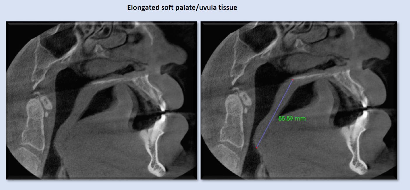
Elongated uvula/soft palate is sometimes implicated in creating narrowing in the oropharynx. Typical length of this soft-tissue complex is approximately 40 mm or less. The image above shows a length that approaches the superior aspect of the epiglottis, with associated airway narrowing.
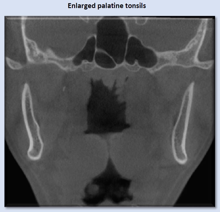
Enlarged palatine tonsils are most commonly seen in children, and demonstrate significant variety in size. The above image depicts considerable enlargement of the palatine tonsils, which is creating blockage of the airway. Regression of the palatine tonsils occurs gradually after the age of 12.
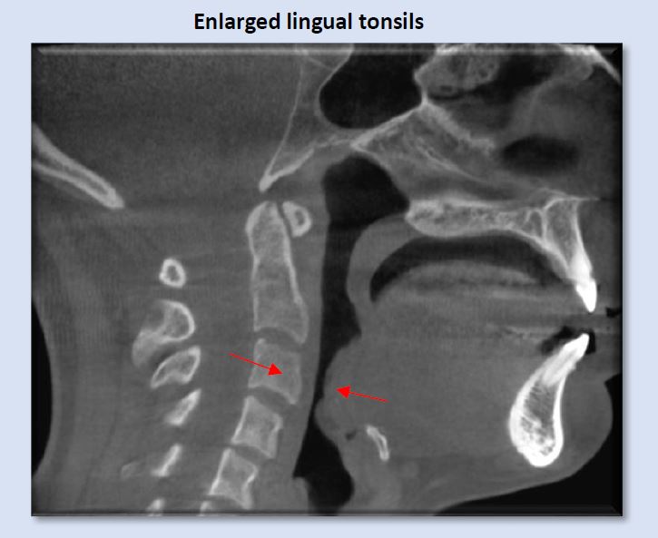
Enlargement of the lingual tonsils is less frequently seen than the pharyngeal or palatine tonsils, but is nevertheless a common finding, and can create significant narrowing of the inferior oropharynx, as shown above. Lordotic curvature of the cervical spine in this instance it exacerbating the constriction.
Commonly seen, but less scrutinized findings relative to risk of sleep-disordered breathing
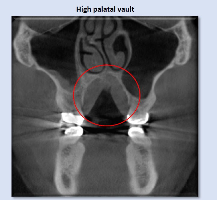
High palatal vault is suggestive of narrowed maxillary alveolar and dental arches, which can result in unilateral or bilateral posterior crossbites, functional shifts, and restriction in the freedom of anterior mandibular movement. It also creates a space for the tongue to be positioned superiorly, which can lead to airway restriction at the superior oropharynx.
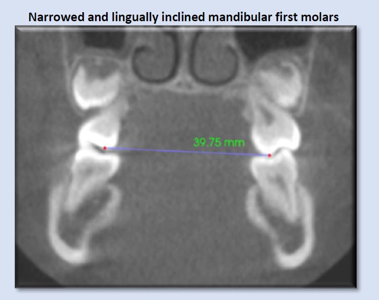
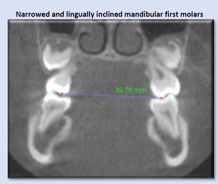
Narrow dental arches often reduce the amount of available tongue space, and may transversely constrict the tongue. This can lead to aberrant tongue shape and position, and subsequent alteration of normal airway space. Rule of thumb: less than approximately 44mm may indicate risk for development of breathing disorder. (Dr. Sean Carlson)
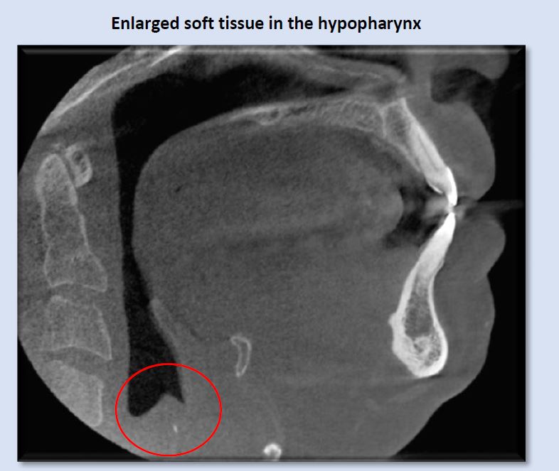
An unusual finding of enlarged soft tissue in the hypopharynx, at the level of the larynx, warrants evaluation medical ENT. The small hyperdensity is likely calcification of arytenoid cartilage.
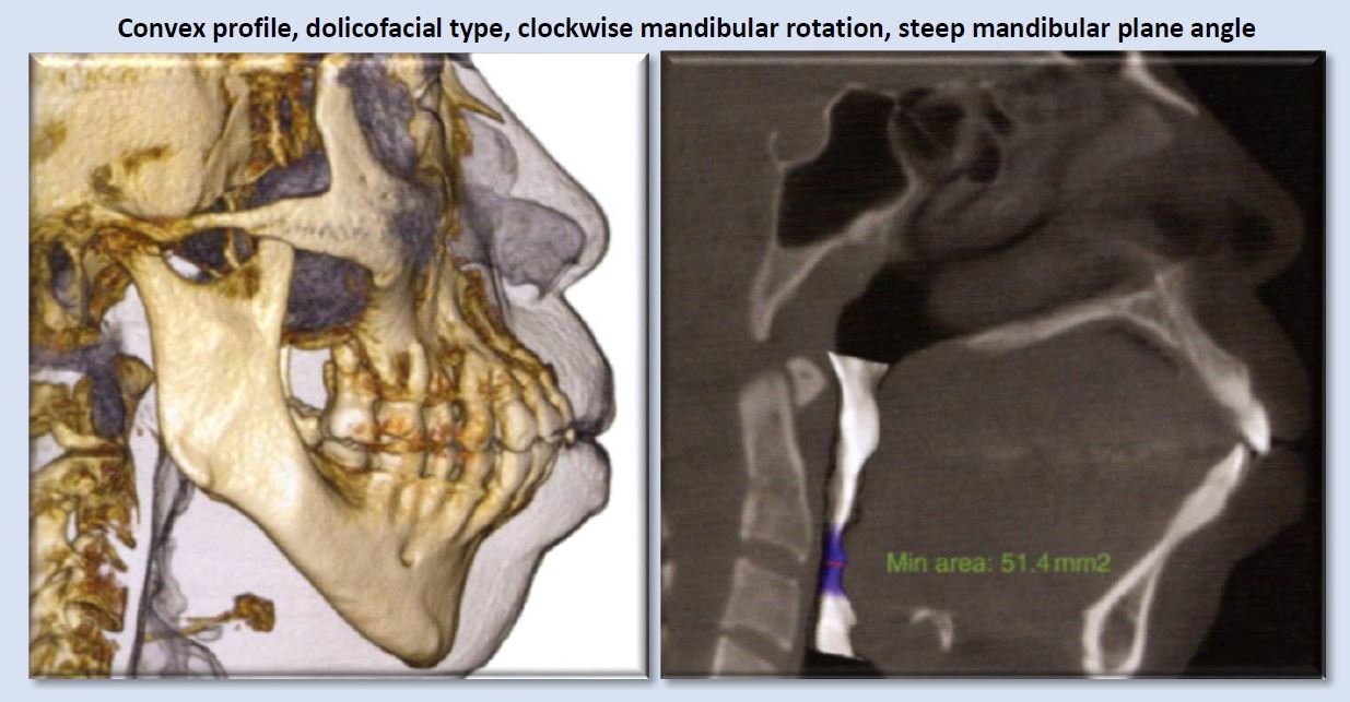
Narrowed airway dimensions are seen more frequently in cases of this facial growth type than other growth patterns.
Less-commonly seen irregularities that indicate risk for presence or development of obstructive sleep-disordered breathing
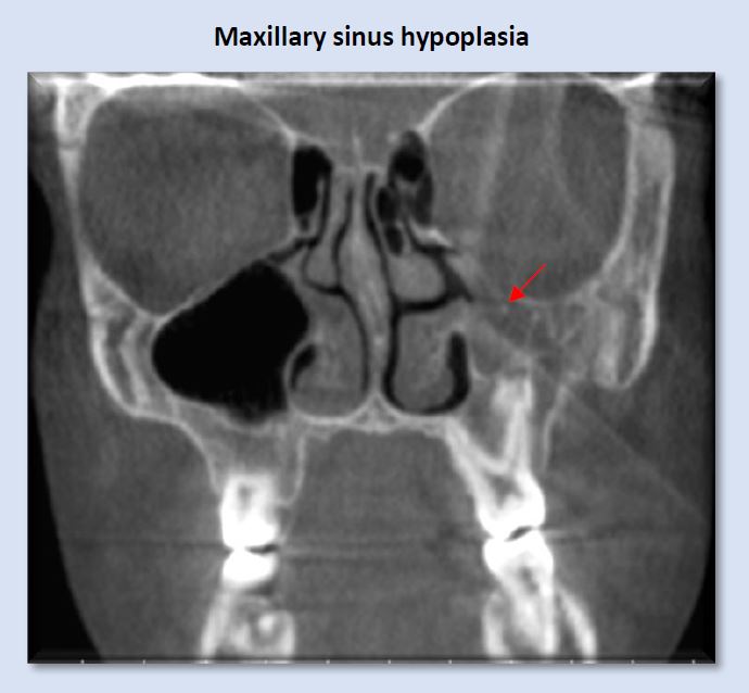
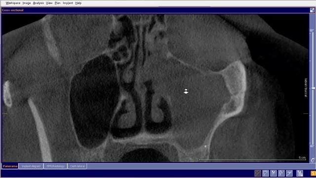
The left maxillary sinus in the image above is considerably smaller than the right, and its lumen is opacified with mucosal thickening. This finding does not necessarily create a condition of sleep-disordered breathing, but should raise suspicion and indicates the need for further assessment.
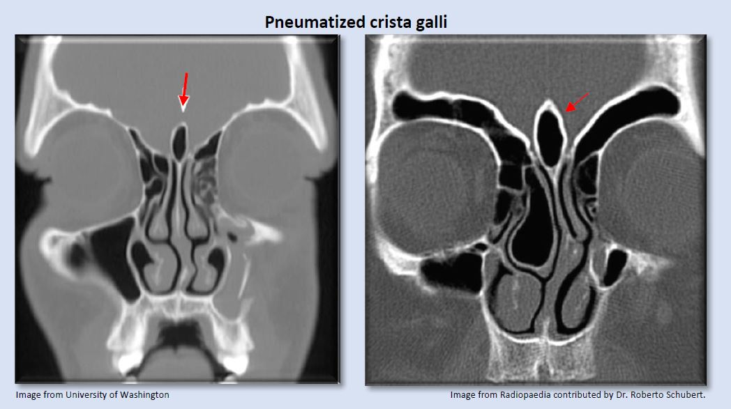
Image from University of Washington Image from Radiopaedia contributed by Dr. Roberto Schubert.
Pneumatized crista galli may communicate with the frontal recess and can potentially obstruct the frontal sinus ostium.
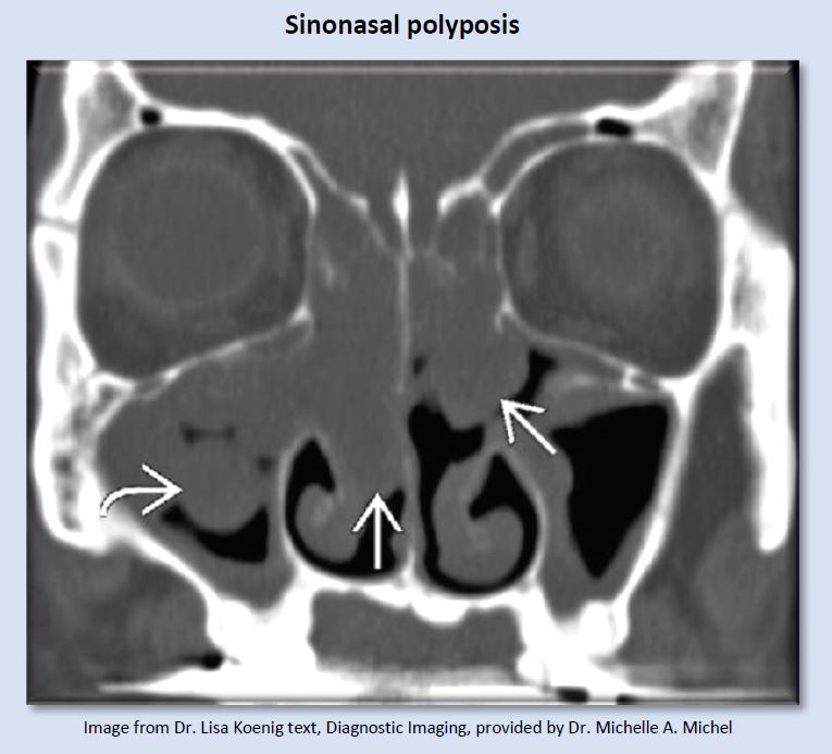
These tissue enlargements are non-neoplastic, inflammatory swellings of sinonasal mucosa that buckles to form “polyps”. Considerable resistance to airflow is created by lesions this size.
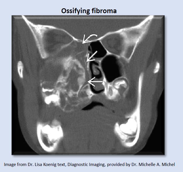
Ossifying fibroma is an expansile benign fibro-osseous neoplasm which can create significant airway blockage.
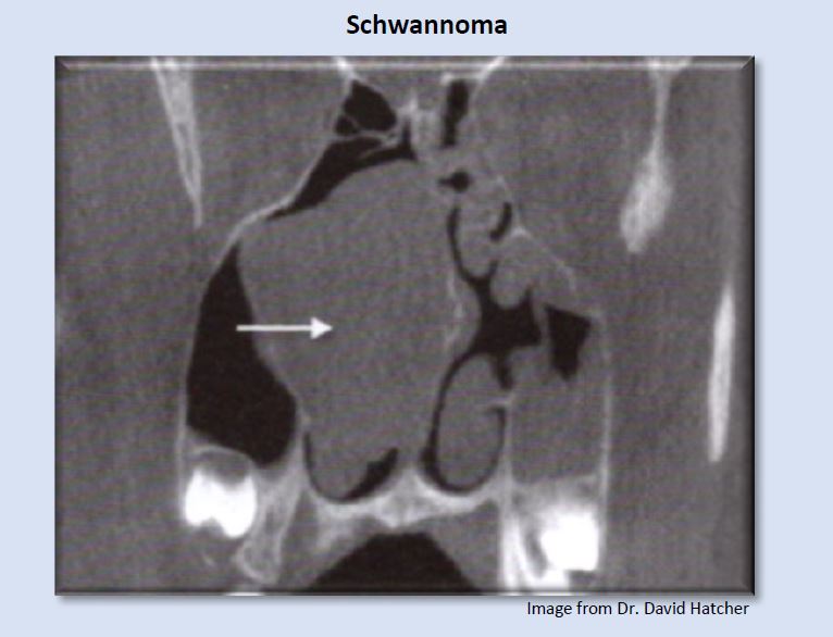
A schwannoma is a normally benign, neural sheet tumor, in this case creating blockage in the right nasal cavity.
The preceding images represent some findings identified on CBCT exams that suggest the possibility of presence or future development of obstructive sleep-disordered breathing. Numerous additional abnormalities not included in this article can create obstructions or disruptions of normal airflow. This flow of air from the environment into the lungs must negotiate a course from the external nasal valves, through the nasal fossa, the nasopharynx, oropharynx, and hypopharynx. Airflow dynamics through this pathway are subject to laws of Poiseuille and Ohm, which show resistance to airflow can create increases in the pressure gradient between the mouth/nose and the alveoli (Hatcher, 2010). Anatomical structures along this pathway involve cartilage, bone, muscles, and mucosa, which are dynamic and can change in dimension and shape in response to normal physiological (swelling and shrinkage of nasal conchae), allergies, infection, and abnormal tissue proliferation, such as polyps or neoplasm.
Click here to submit your scan for an airway assessment

This patient was finally relieved to find out what the source of his exhaustion was. Years of struggling with sleep, being tired and frustrated all day led him to search for solutions. A simple home study test confirmed that he suffered from sleep apnea. More importantly a simple therapy resolved his problems. Watch this testimonial about the life changing experience and find out how you can impact your patient’s lives

 One of the hottest topics in dentistry is the perforation of the sinus floor that we find in posterior maxillary teeth.
The path of least resistance in the upper arch is usually the floor of the sinus. Rarely do we see a fistula on the palate. It can happen, and we can see the purulence on the buccal as well, but most of these draining lesions burrow a path through the floor of the sinus.
If there is good drainage through the osteum the patient generally has no symptoms. So most people can have issue with necrotic teeth or failing root canals and be completely unaware of it. This video below shows a comparison of the two maxillary sinuses.
It should be readily apparent that peri-apical x-rays do not reveal this type of information


You must be logged in to post a comment.