One of the best companies to work with for dental tech needs. They have a vast video training library that makes the transition easy to digital dentistry. I’ve recommended a few of my colleagues purchase the medit through them. It’s been a great year...read moreOne of the best companies to work with for dental tech needs. They have a vast video training library that makes the transition easy to digital dentistry. I’ve recommended a few of my colleagues purchase the medit through them. It’s been a great year!read less - 6/16/2020
Sarju Patel
Perfectly Placed Implant course in San Diego was very good. Armen and Brian are excellent lecturers and educators. A lot of practical tips and pearls of wisdom for those getting into cone beam and guided surgery. Would recommend this course highly. ...read morePerfectly Placed Implant course in San Diego was very good. Armen and Brian are excellent lecturers and educators. A lot of practical tips and pearls of wisdom for those getting into cone beam and guided surgery. Would recommend this course highly. Looking forward to other courses that they offerread less - 2/18/2017
Logan Riggs
I always rely on Frank to help with any questions or concerns regarding our printer. The best in tampa. - 1/25/2023
Barton Davis
Every time I need support for my scanner, the Cad-Ray team is there to help. I recently had a question on how to manipulate a scan and export it back to Medit Scan. Damien logged in and helped me out. Problem solved in under five minutes. Awesome ser...read moreEvery time I need support for my scanner, the Cad-Ray team is there to help. I recently had a question on how to manipulate a scan and export it back to Medit Scan. Damien logged in and helped me out. Problem solved in under five minutes. Awesome service. Thanks Cad-Ray support team!read less - 3/04/2022
Jason Oh
Everyone at CAD Ray has been amazing. Glad I chose them for my Medit and Sprint Ray purchase. Our training with Kaila was awesome. Thank you - 1/04/2023
Cary Ganz
One of the best companies I've dealt with in decades of dental practice. Not only is the product excellent but the support both personally and online has been just wonderful. - 8/08/2021
Blake Ferando
I purchased my medit in April of 2019 from Cad-Ray. The support offered is second to none, and the training videos are some of the best out there. Add to that a great support team that is fast to answer questions and issues, its hard to beat Cad-Ray. - 6/19/2020
Brent Hale
I bought a scanner from Nick Statly at Cad-ray a few months back and have nothing but good things to say about them. They were very helpful with setting up my computer that's linked to the scanner and since then have been very eager to help with ques...read moreI bought a scanner from Nick Statly at Cad-ray a few months back and have nothing but good things to say about them. They were very helpful with setting up my computer that's linked to the scanner and since then have been very eager to help with questions that I had regarding the system.read less - 12/08/2021
Cristy Duval
Kaila is an incredible Rep! Hope Cad-Ray knows what a great employee they have. Thank you Kaila! - 12/16/2021
John T
Frank and the CAD-Ray crew are awesome! They are always available for support with the technology you purchase from them. - 1/25/2023
Minh Van
I was referred to CAD-Ray by Medit Instagram help service. I have purchased Medit i700 from Laura, I was please to work with her and the whole team. They offered the best customer service and the fast responses, especially Laura. I look forward for t...read moreI was referred to CAD-Ray by Medit Instagram help service. I have purchased Medit i700 from Laura, I was please to work with her and the whole team. They offered the best customer service and the fast responses, especially Laura. I look forward for the next purchase.read less - 12/07/2021
Otto Herod
I received my Medit scanner a couple months ago from Cad-ray, and I can't express enough how awesome it is. I have done a ton of research and used the latest IOS from one of the big guys, and due to many software issues I was able to return that mach...read moreI received my Medit scanner a couple months ago from Cad-ray, and I can't express enough how awesome it is. I have done a ton of research and used the latest IOS from one of the big guys, and due to many software issues I was able to return that machine. And thank God, because it was so over priced and came with a $300/month support fee forever! The Medit scanner is as good or better than that one when it was working properly, and for the price it's a no brainier.read less - 9/17/2020
jeremiah choi
Never had customer care like Cad-Ray, you can't go wrong purchasing through them. Trios is a great scanner. All the reps at Cad-Ray are very knowledgeable and helpful and will make sure you are up and running smoothly. Above and beyond customer serv...read moreNever had customer care like Cad-Ray, you can't go wrong purchasing through them. Trios is a great scanner. All the reps at Cad-Ray are very knowledgeable and helpful and will make sure you are up and running smoothly. Above and beyond customer service.read less - 8/27/2022
I purchased Medit scanner few weeks ago . Frank and Nick have been really excellent answering my questions promptly. The scanner itself is wonderful with no back fees , customer service is top notch. The entire team works fast and helps you out. I st...read moreI purchased Medit scanner few weeks ago . Frank and Nick have been really excellent answering my questions promptly. The scanner itself is wonderful with no back fees , customer service is top notch. The entire team works fast and helps you out. I strongly recommend this scanner!read less - 6/17/2020
Update to CAD-Ray as this company has morphed into something even better and grander than it was previously. This is the company where you go to when you need a scanner or 3d printer. Their customer service is second to none and their training on sca...read moreUpdate to CAD-Ray as this company has morphed into something even better and grander than it was previously. This is the company where you go to when you need a scanner or 3d printer. Their customer service is second to none and their training on scanners is top level. Don't buy your scanners anywhere else because Cad-Ray is the only company who knows how to solve any of your problems and provides the best technical support. I recently had purchased a software to mill crowns from my medit to my MCXL. No body could get it to work.12 months in and I was resigned to it not working and not being able to mill in house. With Cad-Ray's tremendous hard work, we were able to get the milling unit synchronized to the inlab and inlab synchronized to clinux and clinux meshed to medit. I am now milling scanned crowns for the first time in about 12 months. Yay Cad-Ray, Thank you!!!!!read less - 3/06/2024
Richard Wu
Great customer service! Had an issue with our dongle and Cad-Ray got it squared away and a new dongle sent right away. - 1/25/2023
Carter Weber
I had a great experience with CAD RAY. I was lucky enough to have Frank DeLuca come down to my office to demo the Medit I700. Needless to say, we were in love with the technology and the great hands on demo. CAD RAY overnighted me the scanner and we ...read moreI had a great experience with CAD RAY. I was lucky enough to have Frank DeLuca come down to my office to demo the Medit I700. Needless to say, we were in love with the technology and the great hands on demo. CAD RAY overnighted me the scanner and we were off to the races. Any time we have had a technical question, Frank has personal helped me or put me in touch with one of his colleagues if he wasn’t available. All around, it was as 5 star experience!read less - 12/16/2021
Chase Funk
This has been awesome, to be honest I have know idea how to use it but our team members have picked it up so easy!! - 6/16/2020
arthur lyford
I cannot say enough about the support I have received from the beginning. I chose CadRay ultimately because of the support reviews...I can attest first hand...they are all right on...though I have been practicing for more than 35 years, this old dog ...read moreI cannot say enough about the support I have received from the beginning. I chose CadRay ultimately because of the support reviews...I can attest first hand...they are all right on...though I have been practicing for more than 35 years, this old dog has been taught a lot of new tricks from the support staff at Cad Ray...Truly impressed with every interaction so far! Thanks 10/4/2023 And they did it again today with ten minutes before the pt came in 3Shpe server would not connect with the computer and Andy got to 3Shape directly and had us up and running...thankfully I didn't have to call anyone but CadRay...thanks again....read less - 10/05/2023
Yaqi Mu
I absolutely love using the Medit i500 Intra-oral scanner!!! The i500 scanner is small and easy to use on all patients. It is fast and gives a very clear image. I also think its very cool that you can change the music setting to whatever song you m...read moreI absolutely love using the Medit i500 Intra-oral scanner!!! The i500 scanner is small and easy to use on all patients. It is fast and gives a very clear image. I also think its very cool that you can change the music setting to whatever song you may like! I have used a few different scanners since i have been a dental assistant and have had several complications as far as: how long the scanner would take to load the image, The scanner not catching the image and even the system constantly kicking me out. With the i500 intra-oral scanner i have the BEST experience. I am happy and my patients are happier! I recommend the Medit i500 Intra-oral scanner to anyone who has never used it before! You wont be disappointed! 5 Stars for sure!!!!
- Samantha Brown @ Southern Oak Dental in Conway SC.read less - 6/17/2020
Frank and the Cad Ray team have been nothing short of amazing. I continue to purchase digital equipment from Cad Ray because their support is unlike any in the dental industry. Frank has been instrumental in helping my team get the most out of our pr...read moreFrank and the Cad Ray team have been nothing short of amazing. I continue to purchase digital equipment from Cad Ray because their support is unlike any in the dental industry. Frank has been instrumental in helping my team get the most out of our products.read less - 1/25/2023
Jeffrey Martins
Service at CAD-Ray has been really great. About 6 months ago I purchased a Medit i700 scanner from them and have been really happy with it. Fortunately, I haven’t run into many problems, but if I need help they are so easy and friendly to work with. ...read moreService at CAD-Ray has been really great. About 6 months ago I purchased a Medit i700 scanner from them and have been really happy with it. Fortunately, I haven’t run into many problems, but if I need help they are so easy and friendly to work with. When my scanner did stop working, they quickly got me set up with a new one. If I have a computer question, they offer to log in and look at the computer with you. If you’re in the market for an intraoral scanner or any of their other products, I encourage you to talk with them to meet your goals. Thanks CAD-Ray!read less - 11/04/2022
Madhavi Chavda
Still beginner to use IO scanner. best customer service. Live training was very useful. Andy Nova was great in improving my skill for scanning and showing me all features. Thank you. - 5/19/2022
Great scanner at a good price...Excellent customer service . I never want to take a conventional impression again! Best upgrade to my office in years. - 11/16/2021
Michael Gagaoudakis
Awesome company. The video collection CAD-Ray has put together for their equipment is unparalleled. There is literally no other company that has a library of learning tools like Armen and his team have put together. I highly recommend this company if...read moreAwesome company. The video collection CAD-Ray has put together for their equipment is unparalleled. There is literally no other company that has a library of learning tools like Armen and his team have put together. I highly recommend this company if you are considering making a digital equipment investment. 5 stars!read less - 6/16/2020
AJ Ganir
Cadray has great support and service! They are very responsive to questions. Love the new medit scanner! - 5/06/2021
Trident Dental
Great help when you need it. Frank, Armen and team will take care of you. - 12/10/2021
Lora Wonderly
Thank you Frank DeLuca for being so accessible and making everything right again! Customer service is above and beyond. We also love our Medit Scanner - we would be lost without it! - 1/25/2023
Kirk Arritt (fldnstrm)
Whatever digital workflow addition you want to add to your dental practice look no further than Cad-Ray. Top notch support and training. - 1/29/2023
Victoria Rinando
Danielle was super helpful and kind trouble shooting to get us back up and going very quickly this morning. We appreciate it! - 4/15/2025
Melissa Poynter
Very pleased with Heather :) She has been able to solve any and all issues I may be having, and does so within the same day if not right away! - 6/16/2022
Mostafa Koperly
I love my medit scanner. I purchase many dental equipments each year and by far it’s the best thing I got for the bucks I spent ( beating my 6 digits equipments ).
We have omnicam and I hated it, multiple crushes, expensive monthly service fee, hor...read moreI love my medit scanner. I purchase many dental equipments each year and by far it’s the best thing I got for the bucks I spent ( beating my 6 digits equipments ).
We have omnicam and I hated it, multiple crushes, expensive monthly service fee, horrible support, etc. I was so frustrated and had to look for an alternative. Many mentioned itero to me and I was about to purchase it and suck another monthly fee until I came by Armen’s video about medit on one of the Facebook group in 2018. I was surprised with the image and the speed and started digging more and contacted Frank to explain the scanner more. Ended purchasing it late 2018 and I’m a happy user Since after. The support is excellent, Frank is there when you need any help plus the Facebook community is there to answer anything. Recently, I attended Armen’s course to learn how to mill from the medit and I got shocked by the AI and the options that the software has. This machine is a beast and you won’t regret it getting it from Armen and Frank. They go beyond and not like other salesman or equipments where you are left behind after they sale you and finish their training. We are in 2020 and I still get the same support as I bought it in 2018.read less - 1/09/2020
Six Stars! On a scale of one to five, I give CAD-Ray six stars. They really are that good. If you are purchasing an intra-oral scanner, I would recommend buying the Medit I-700. It is a dream machine. But, if you want incredible service every time, y...read moreSix Stars! On a scale of one to five, I give CAD-Ray six stars. They really are that good. If you are purchasing an intra-oral scanner, I would recommend buying the Medit I-700. It is a dream machine. But, if you want incredible service every time, you should buy your scanner from Cad-Ray. They have come through with flying colors each time I have contacted them. Their sales team great and their service is amazing. They have volumes of educational videos available, as well. I have worked with Jonathan, Damien, Frank, Armen and Laura. In a time where we are seeing the opposite, CAD-Ray will totally blow you away with the entire experience. I totally appreciate them and their value.read less - 11/01/2021
Jeff Keh
I love my medit i-500. Cad-Ray has wonderful customer support, I can not imagine getting a scanner from anyone else. Armen and Frank are great! Thanks again. Will recommend cad-ray to all my friends. - 6/16/2020
Ellen Huang
Armen created series of these very helpful videos. They helped us tremendously in breaking into the new scanner we purchased. No matter you just got into digital dentistry or you are quite experienced with different fields of data acquiring or treatm...read moreArmen created series of these very helpful videos. They helped us tremendously in breaking into the new scanner we purchased. No matter you just got into digital dentistry or you are quite experienced with different fields of data acquiring or treatment planning, you will find those being tremendous help.read less - 5/24/2020
I was on the fence on getting a scanner for years and finally pulled the trigger. CAD-Ray's support and knowledge has made this one of the best investments in my practice to date. When I spoke with Damien on the phone about my options he literally sa...read moreI was on the fence on getting a scanner for years and finally pulled the trigger. CAD-Ray's support and knowledge has made this one of the best investments in my practice to date. When I spoke with Damien on the phone about my options he literally saved me thousands after figuring out what my exact needs were. I went with the Medit i600, MSI laptop and 3D dental systems cart. The final product looks and feels as premium as it gets.read less - 2/21/2024
Kelly Betts
Customer service has always been top-notch! I personally worked with Wayne Glassoff and he has been super helpful getting our office up and running with 3D printing and has always been a great resource and highly responsive whenever I need anything o...read moreCustomer service has always been top-notch! I personally worked with Wayne Glassoff and he has been super helpful getting our office up and running with 3D printing and has always been a great resource and highly responsive whenever I need anything or have any questions.read less - 9/24/2022
Yuriy Yakubov
Got Medit scanner from CAD-ray 5 months ago. Today got help from Rayan. Rayan has a lot of patience ,explained everything I asked him . Absolutly satisfied. Great service, great support. - 10/19/2023
Krystyna
I recently purchased Medit scanner and my assistant and I went through training with Andy. He was great, knowledgeable and patient with us. Customer service is great! - 2/05/2023
Francois Dillinger
These guys are the best. They provide so much help and insight with the Medit. I can't say enough great things about them and their continued support. I truly appreciate everything!! - 6/16/2020
Tommy Han
Awesome service. Bought a Medit and was able to learn how to use it simply by watching Cad-Ray's support and education videos. Three thumbs up! - 6/16/2020
Caleb King
Kaila Larson is the support specialist for our office and has been outstanding. She gets back to us quickly with any questions we have, and will log into the computer and fix issues so we don't even have to worry about them. She is extremely knowled...read moreKaila Larson is the support specialist for our office and has been outstanding. She gets back to us quickly with any questions we have, and will log into the computer and fix issues so we don't even have to worry about them. She is extremely knowledgeable about the MEDIT scanner and the supporting software. She responds to calls and texts or emails and will communicate with us in whatever way is most convenient for our office. She has saved us hours of time and headache by always being available to help.read less - 5/25/2022
Mehryar Ebrahimi
Great costumer service. I needed a part for my i700 and they were able to ship overnight. No down time. - 5/06/2022
Steven Acker
The i700 provides amazing ease of use and versatility for any digital restorative application. It’s been game changing for our practice. CAD-Ray’s amazing support and Medit’s constant improvement of the software are revolutionary. I’ve been taking di...read moreThe i700 provides amazing ease of use and versatility for any digital restorative application. It’s been game changing for our practice. CAD-Ray’s amazing support and Medit’s constant improvement of the software are revolutionary. I’ve been taking digital impressions for over 15 years with other systems and nothing comes close to the Medit.read less - 8/27/2021
Overall great company to work with. They sell wondeful products and give stellar service for a much lower price than any of the supply houses. I can't recommend them enough. - 8/19/2022
Jared H
Purchasing my medit i700 from Cad-Ray was a great decision. I did my first training with Kaila and she was fantastic! Super knowledgeable, patient and truly helpful in making sure I was ready to hit the ground running with patient care. I put a call ...read morePurchasing my medit i700 from Cad-Ray was a great decision. I did my first training with Kaila and she was fantastic! Super knowledgeable, patient and truly helpful in making sure I was ready to hit the ground running with patient care. I put a call into cad-ray support in the middle of a case and sure enough Kaila was also the one to answer and handle the situation. She jumped right on my computer and had things fixed in a matter of a few minutes. Awesome support, great staff and overall super positive experience with Cad-ray thus far!read less - 5/06/2022
Brian Wilkinson
This company is genuinely amazing. Amazingly good products, but the thing that sets them apart is the support. Frank and Sean have answered any questions I have unbelievably fast. And I LOVE the DOF Craft 5x milling unit. Learning the flow of same da...read moreThis company is genuinely amazing. Amazingly good products, but the thing that sets them apart is the support. Frank and Sean have answered any questions I have unbelievably fast. And I LOVE the DOF Craft 5x milling unit. Learning the flow of same day milling was tricky for me, but they held my hand the whole way. Can’t go wrong here.read less - 1/06/2024
Ma. Teresa Santana
Best support and customer service ever! My scanner is long past warranty and they still answer all my questions. When it's time to upgrade I'll be buying from them again. A friend bought same scanner from another vendor and got zero support. I had to...read moreBest support and customer service ever! My scanner is long past warranty and they still answer all my questions. When it's time to upgrade I'll be buying from them again. A friend bought same scanner from another vendor and got zero support. I had to help them. Told her next time buy from Cad Rayread less - 5/10/2024
Ravi Sawhney
Fantastic folks. I'm an orthodontist and opened an office in 2020. They helped me find the perfect intraoral scanner to suit my needs. Not too much or too little, and a great price. Every time we have a technical question, a sharp human answers the p...read moreFantastic folks. I'm an orthodontist and opened an office in 2020. They helped me find the perfect intraoral scanner to suit my needs. Not too much or too little, and a great price. Every time we have a technical question, a sharp human answers the phone, troubleshoots, and remotes in when needed-- navigating MS updates and graphics card issues. My i500 died this week. They overnighted me a trade-in at a totally reasonable price, and even shipped me a laptop to drive the i600 while I got a new one (they knew my 2020 laptop wouldn't keep up!). CAD-Ray has consistently hit it out of the park.read less - 4/14/2025
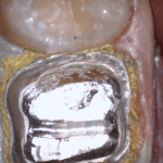
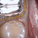
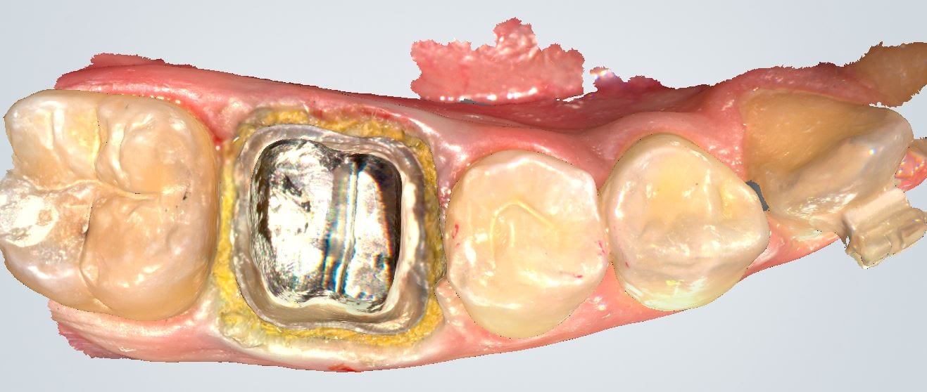
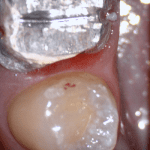
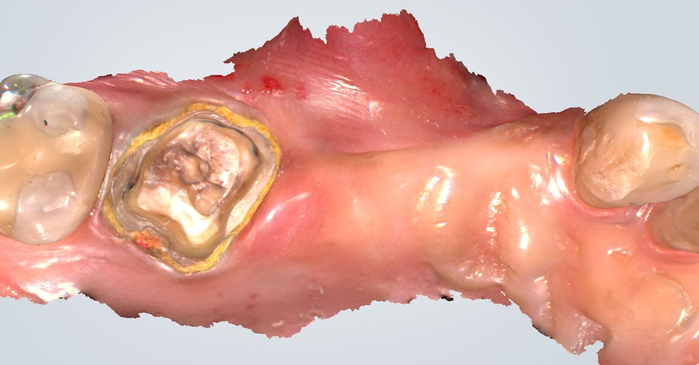
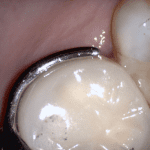
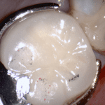
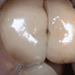
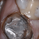
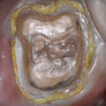
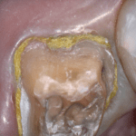
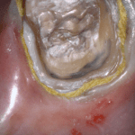
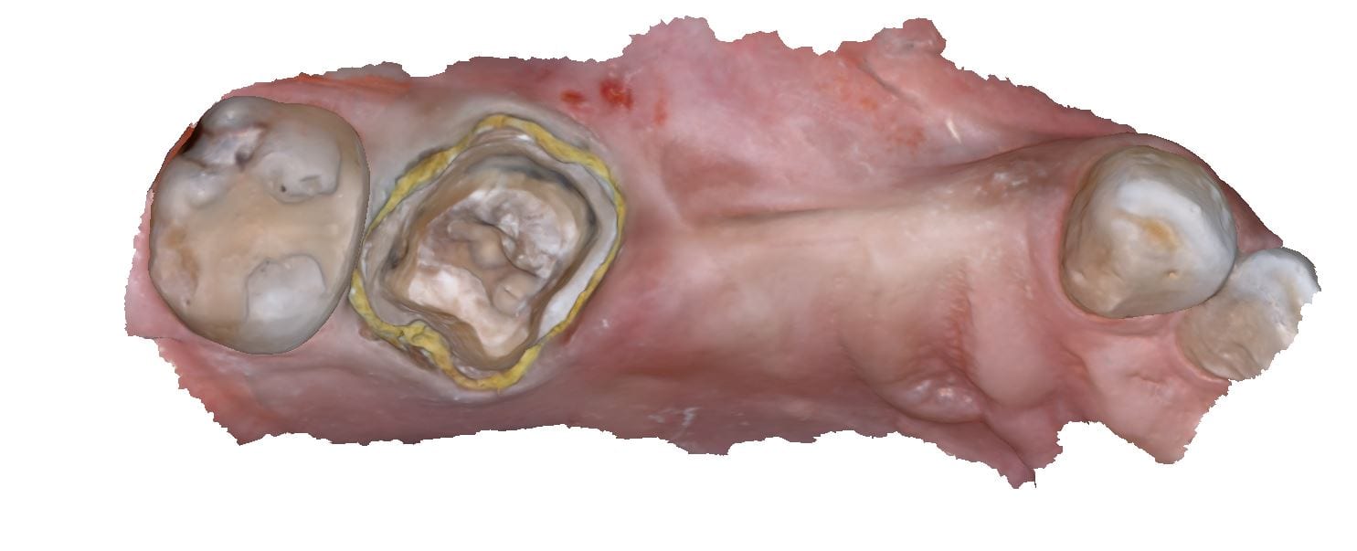
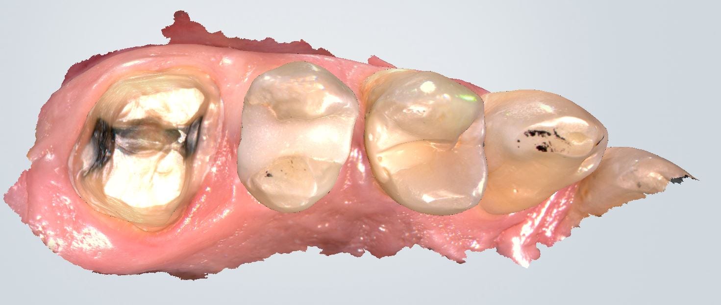
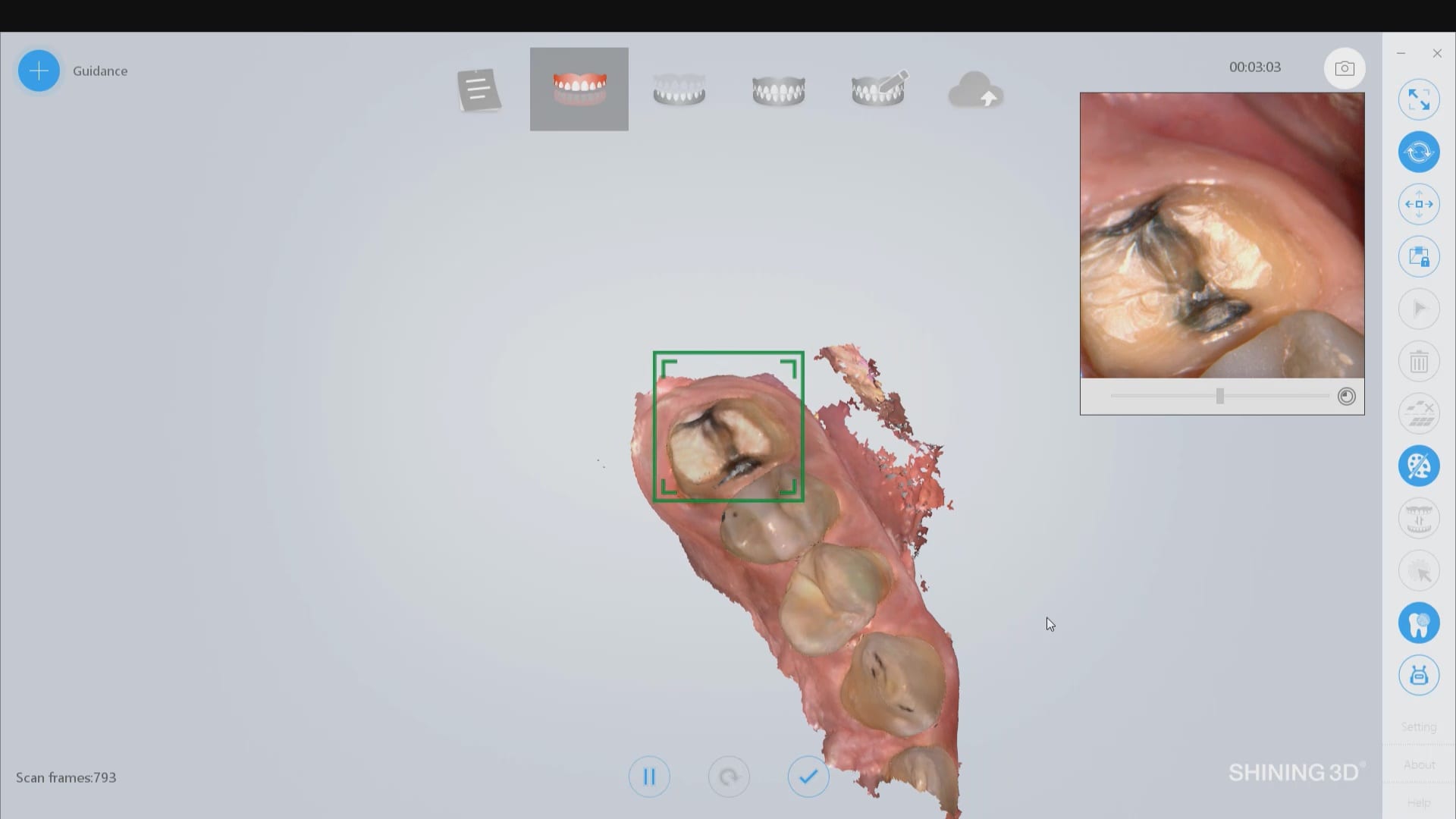
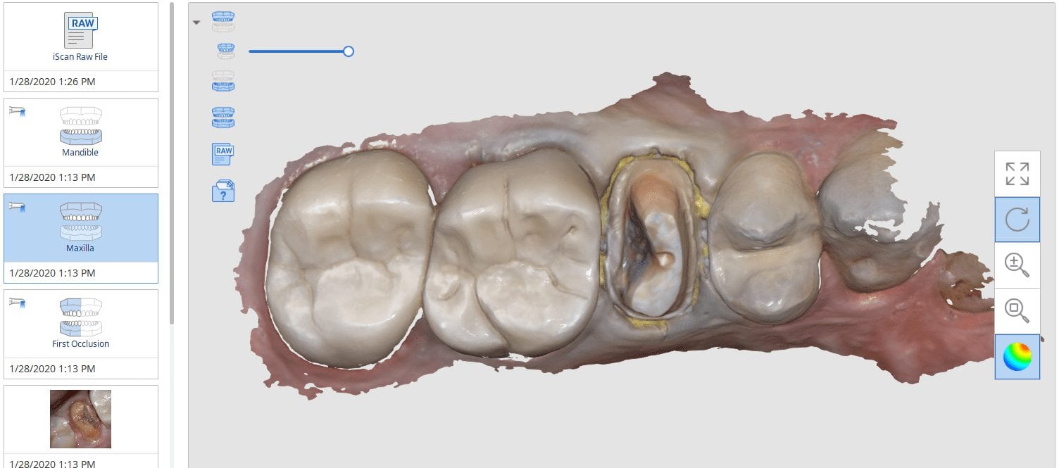
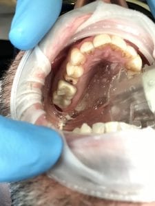
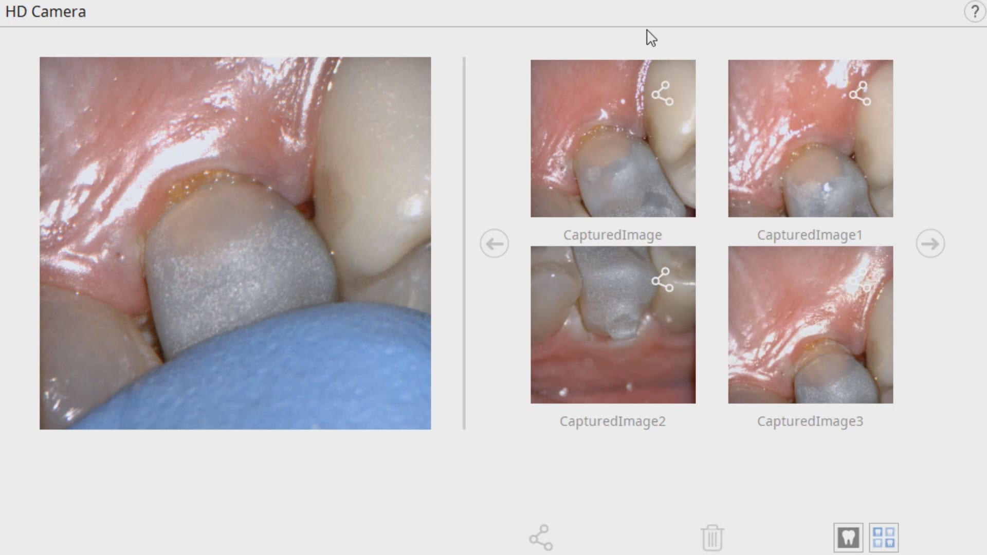
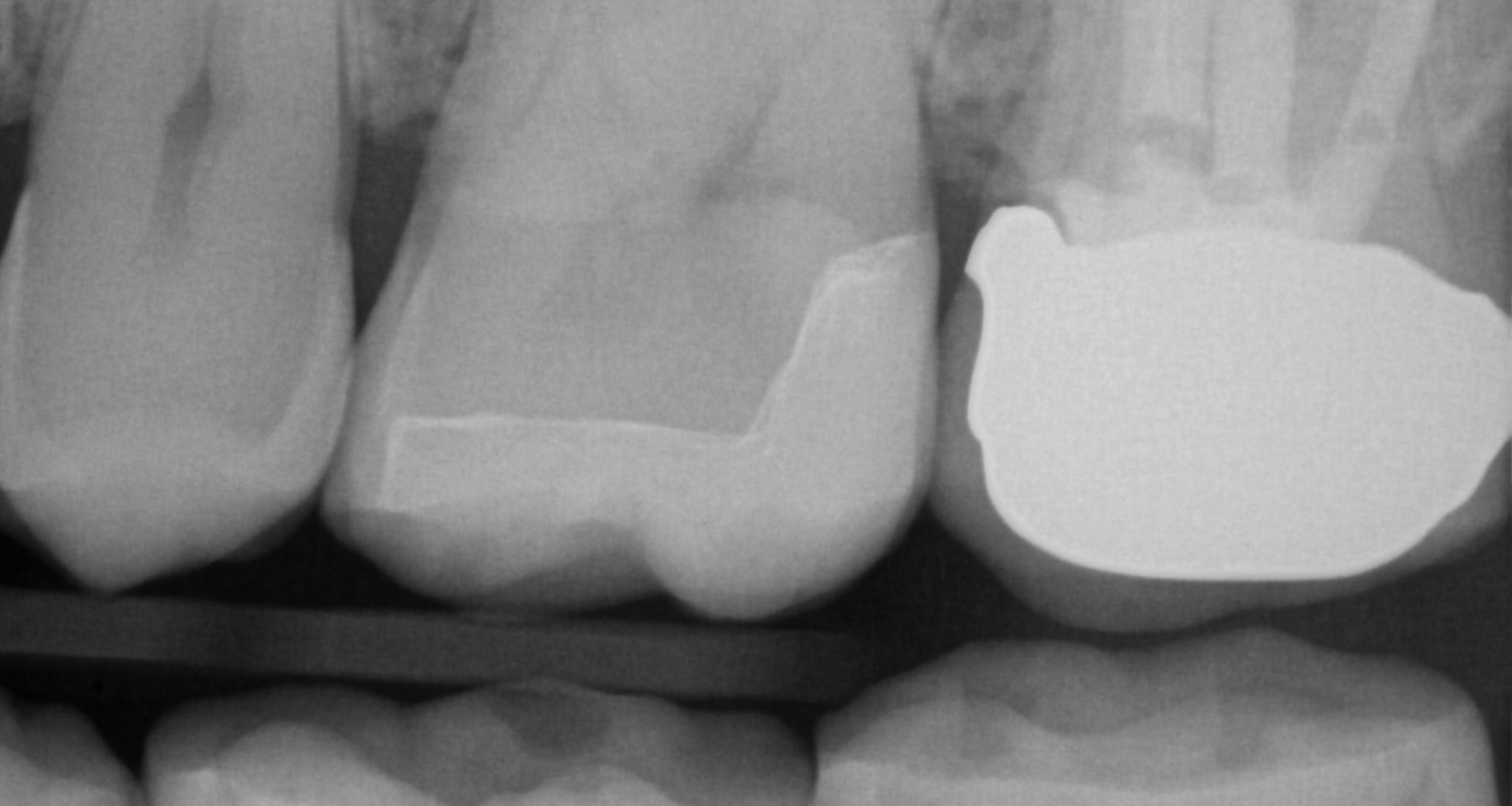
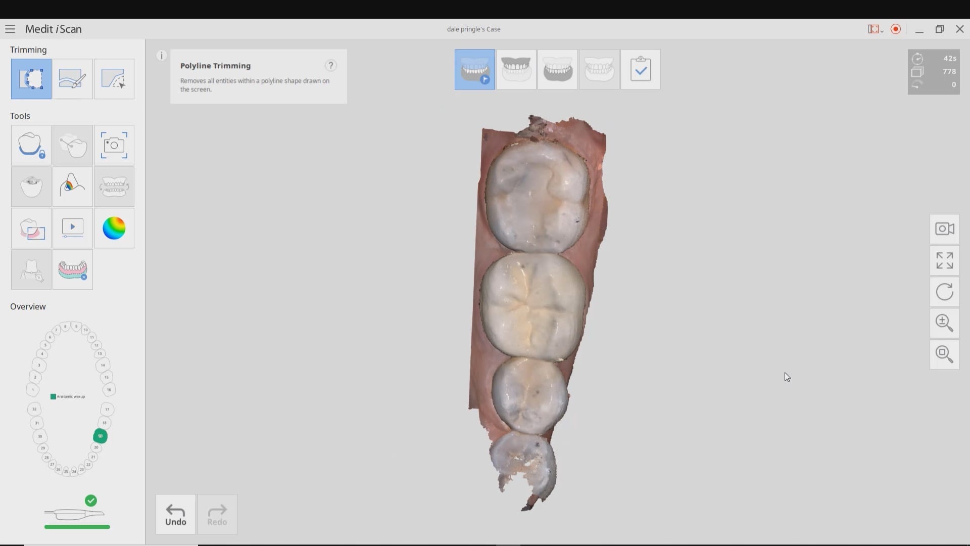
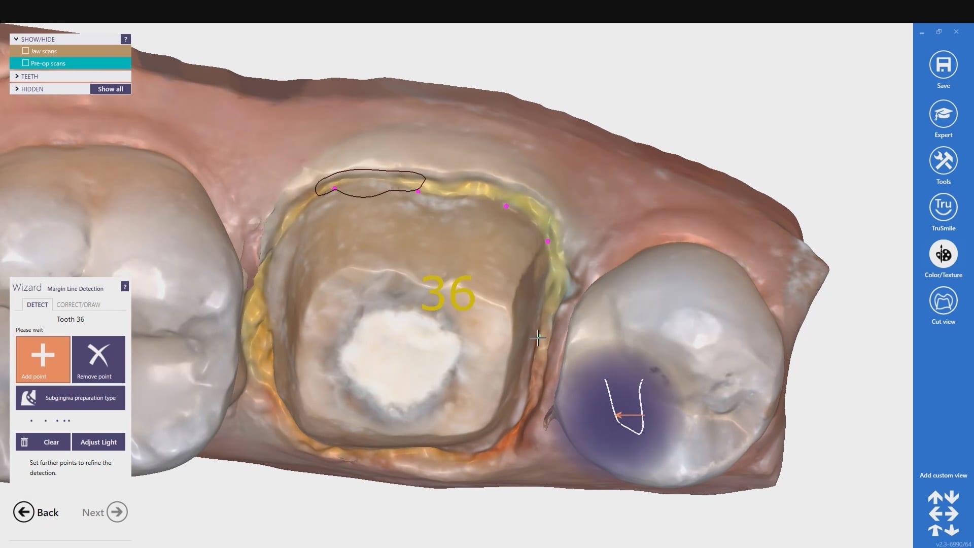
In this clinical video we demonstrate how to scan a molar preparation for the replacement of a crown with recurrent decay and open margins. The molar was root canal treated and the tissue was inflamed. the preparation was imaged and a temporary was fabricated to allow the tissue to heal properly.
The main point of this video is to show how to capture the contacts of the adjacent teeth and the deep marings
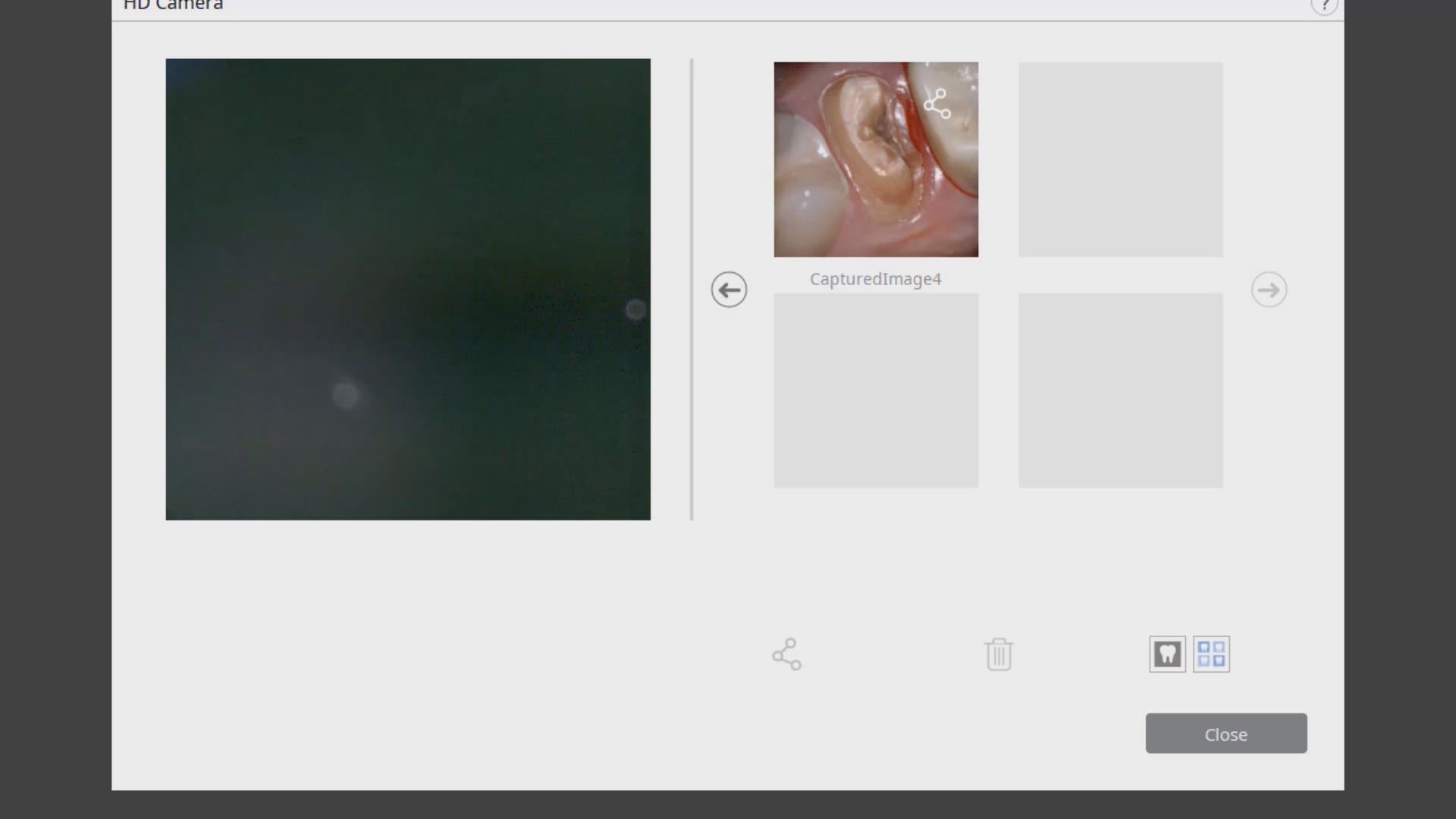
In this video we demonstrate how the Aoralscan from Shinning 3D captures deep margins.
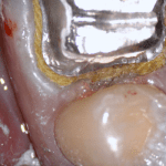
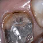
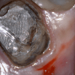
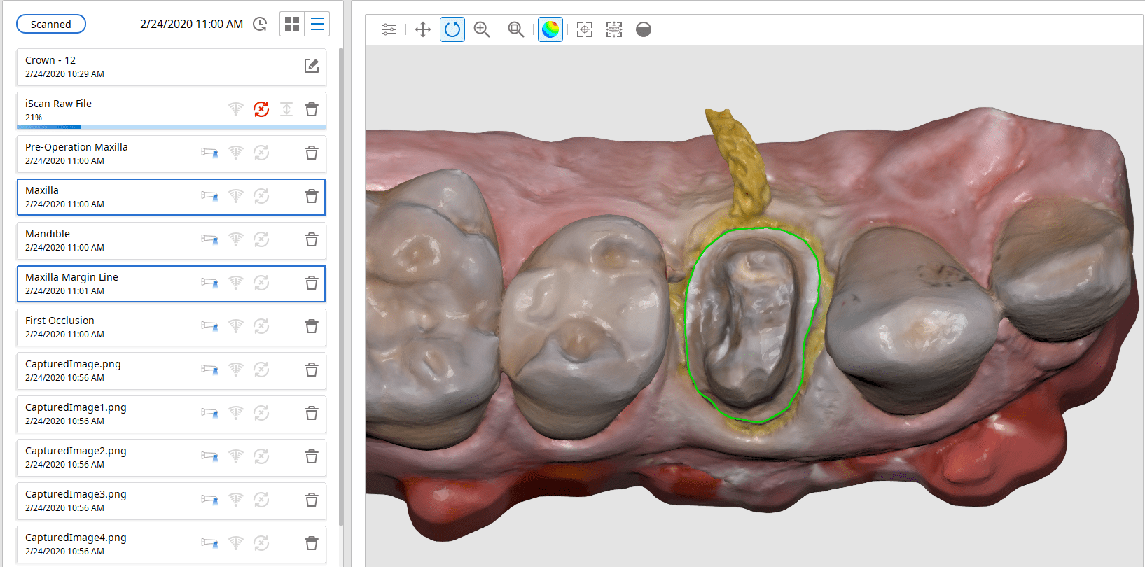
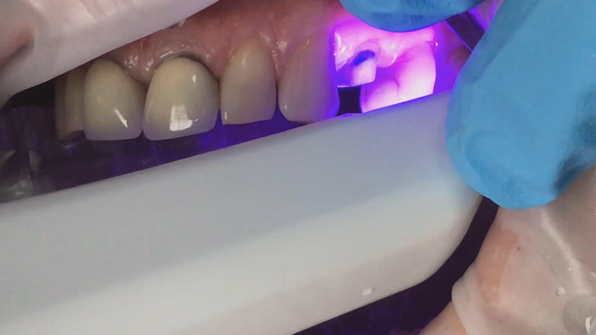
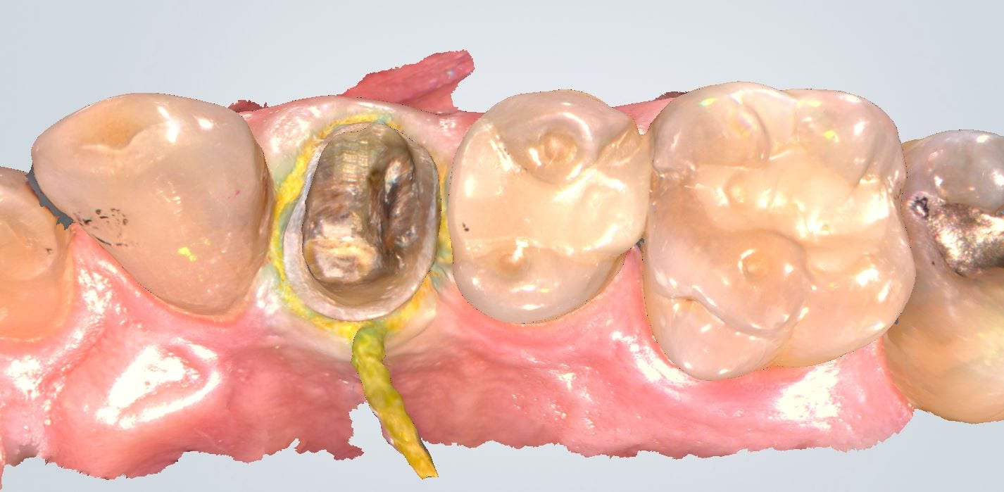
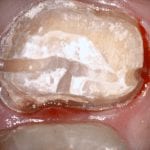
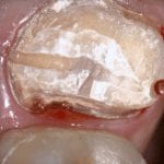
An old PFM crown warranted replacement due to open margins and recurrent decay. After the crown was removed, the margins were refined and the tissue was displaced with expasyl and retraction cord.
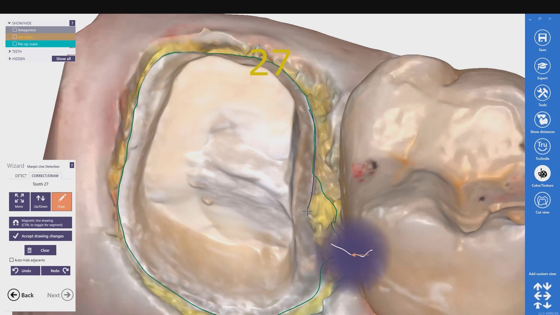
This video is deliberately captured slowly so a new user can appreciate how to hold the camera to capture the margins and the contacts of the adjacent teeth. You also have the opportunity to place your own margins and the path of draw before submit the case to the lab.
This case was scanned by two different scanners. Once by the Medit i500 and another time with the Aoralscan. Both the meshes are included so you can compare the two. It was scanned to deliver a case that retrofits a partial denture
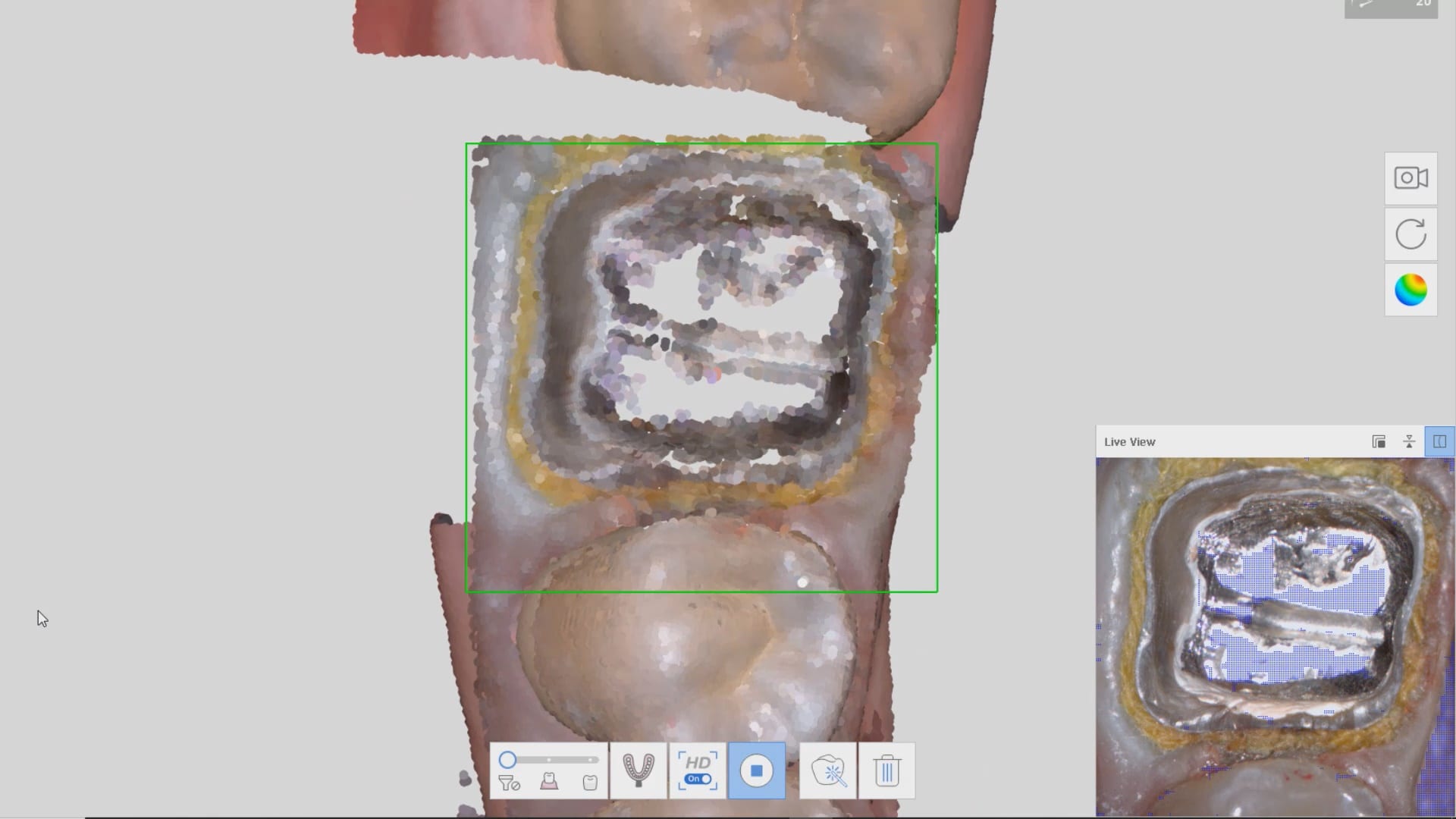
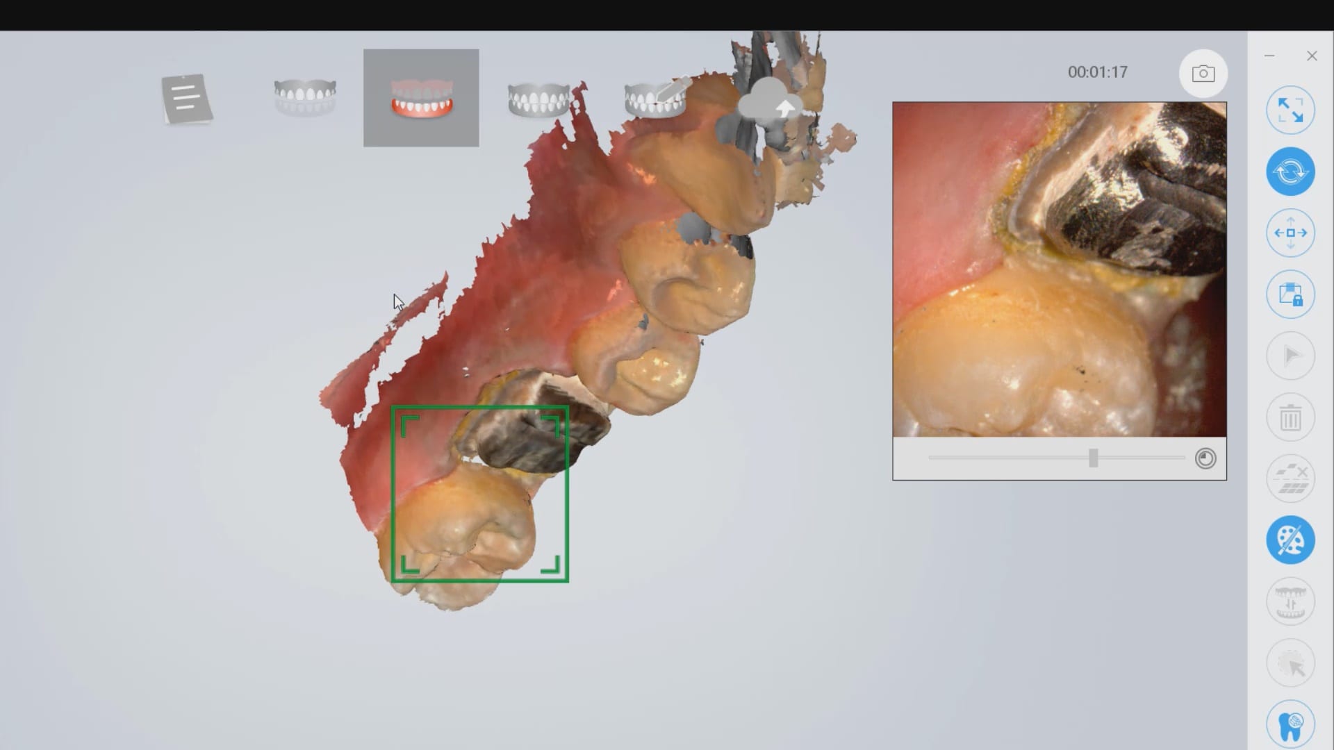
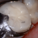
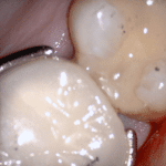
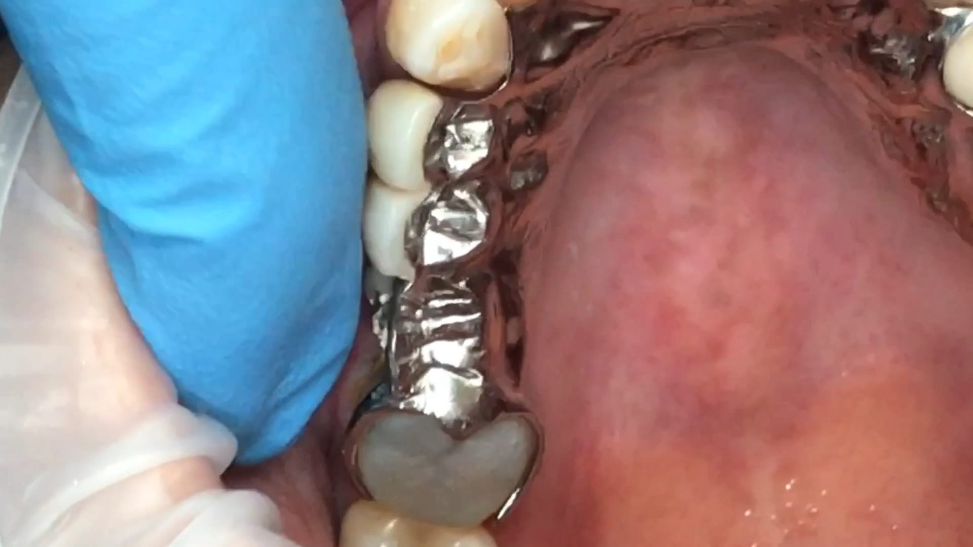
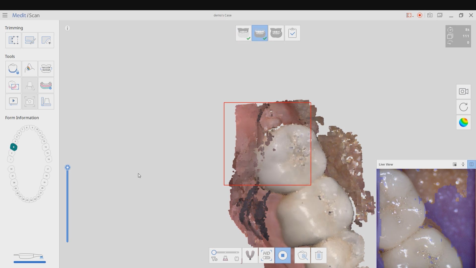
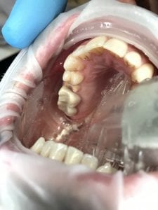
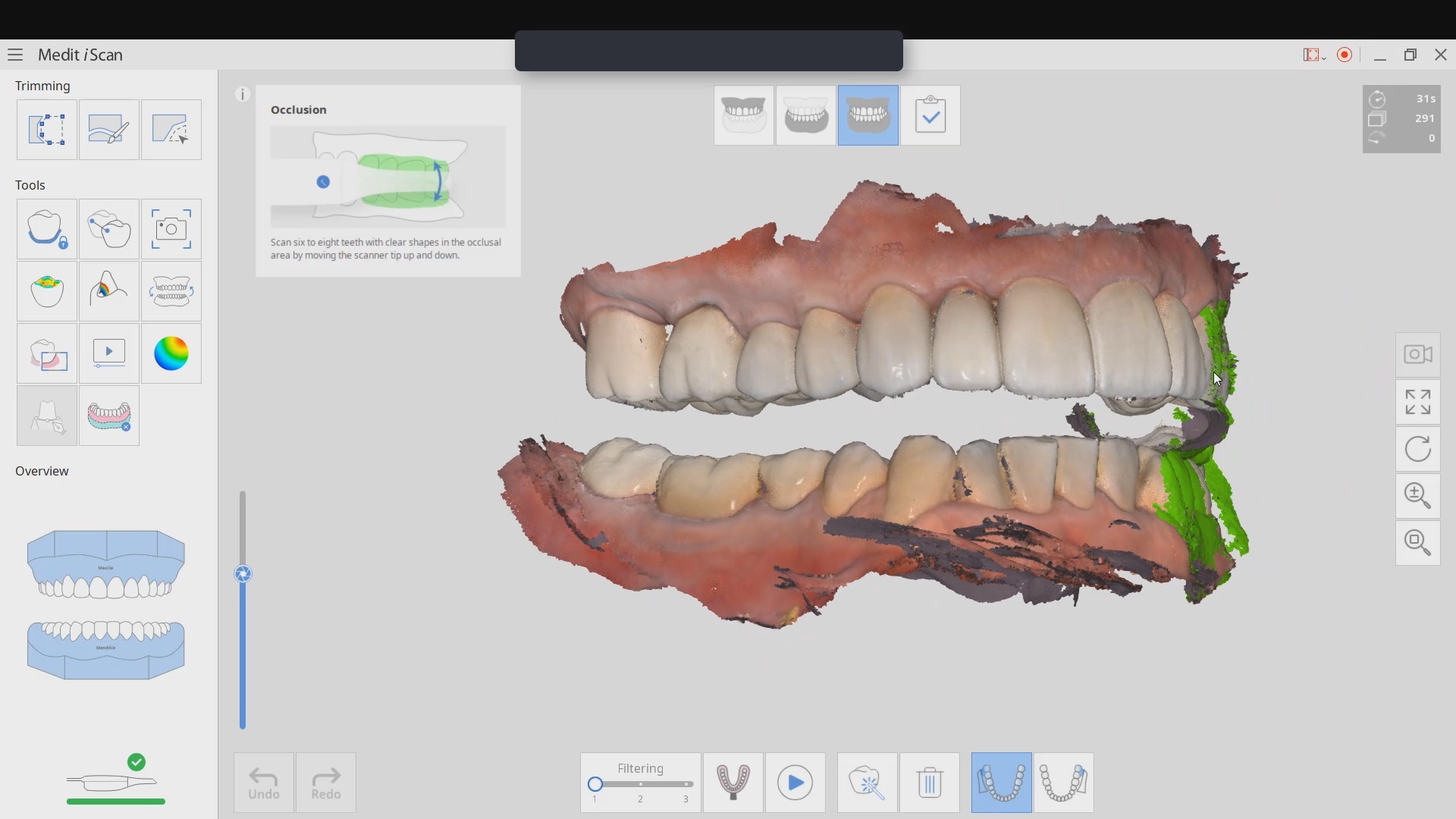
Most manufacturers recommend that you start your imaging at the second molar area, which is the least practical area to start with. The tongue and the lip and saliva are a quick distraction as the scanner does not know what you are trying to image. The incisal edges of lower anterior are also a tough place to start as the incisal translucency lets the light transmit through the enamel instead of reflecting to the cameras.
A good place to start is the second premolar first molar area where you can use the tip of the scanner to displace the tongue. Reducing the focal length to 12 mm’s allows the user to hide hard and soft tissue that can impede the rate of image capture. Watch the deliberate movement of the camera that helps the user manage the area to be captured with relative ease
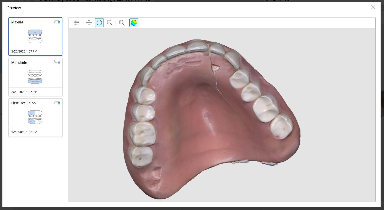
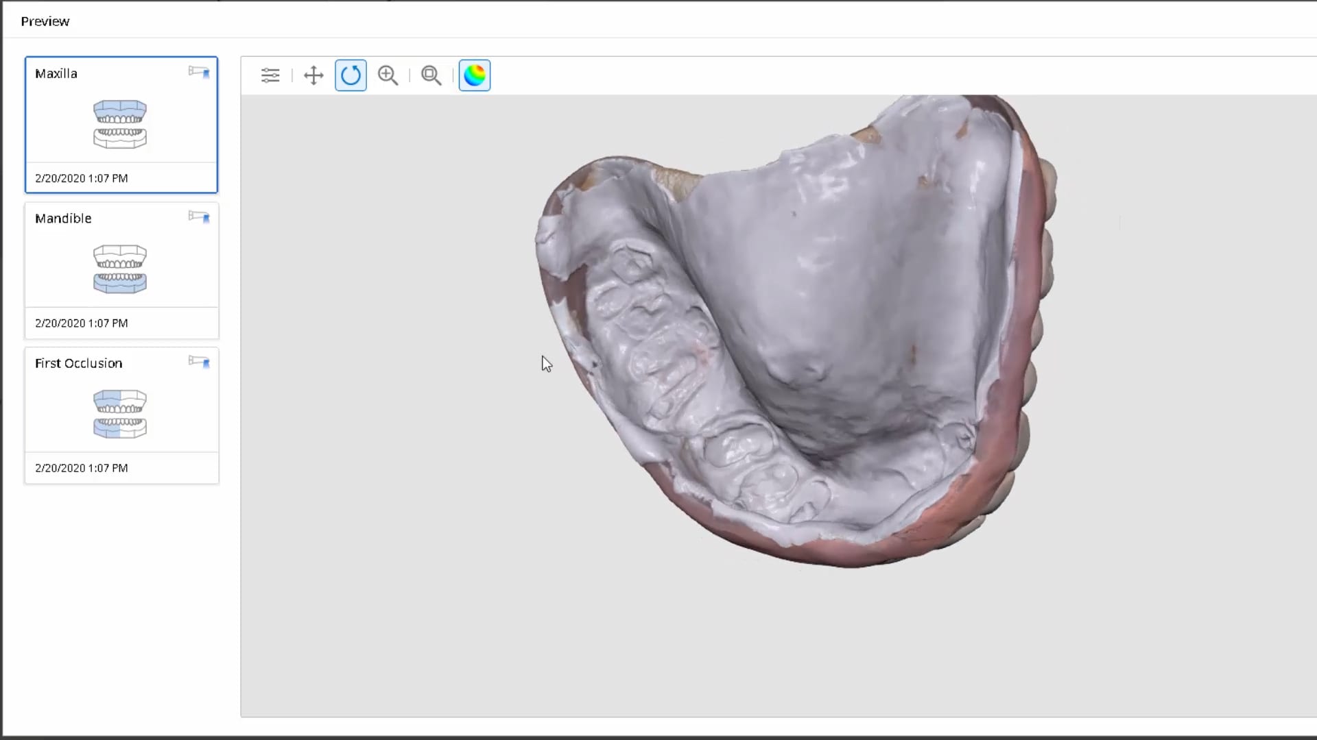
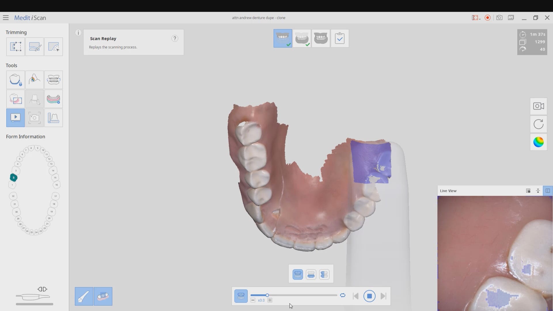
Medit i500 was used to scan and duplicated a fractured denture. It was originally scanned in the patient’s mouth to capture the opposing and the bite and then submitted to the lab for fabrication
In this video we review with the instant replay feature of the medit i500 on how to scan a denture and not introduce double images or errors in the model. We first scan the occlusale surfaces of the denture intra-orally (this does not really matter as the software doesn’t know any differently), we then image the opposing, and then bite. We then remove the relined upper broken denture and continue the imaging to capture the intaglio
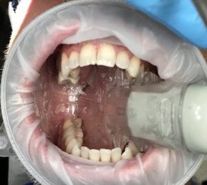
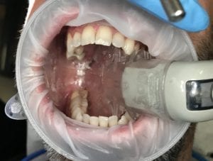
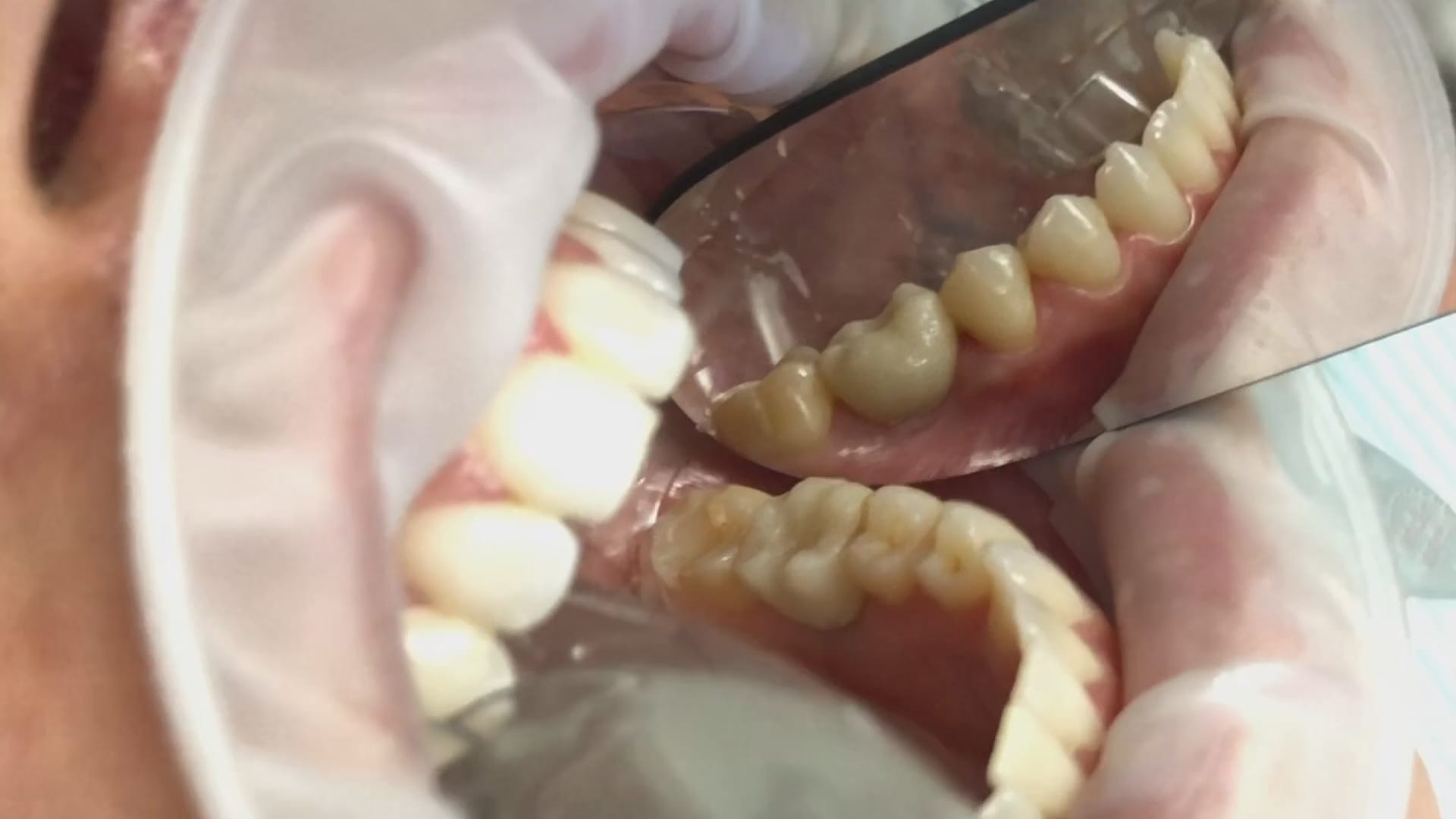
In this case presentation, we introduce the Shining Aoralscan for beginner doctors who want to get into digital impressions. Proper isolation and retraction is a key element of scanning. In this demonstration we showcase how a new user can easily control the operating field to deliver high quality restorations
Proper isolation and retraction is key for all intra-oral scanners. In this video, you can appreciate how the upper and lower arches were isolated, the margins were exposed with retraction cord and imaged with the shining 3d aoralscan
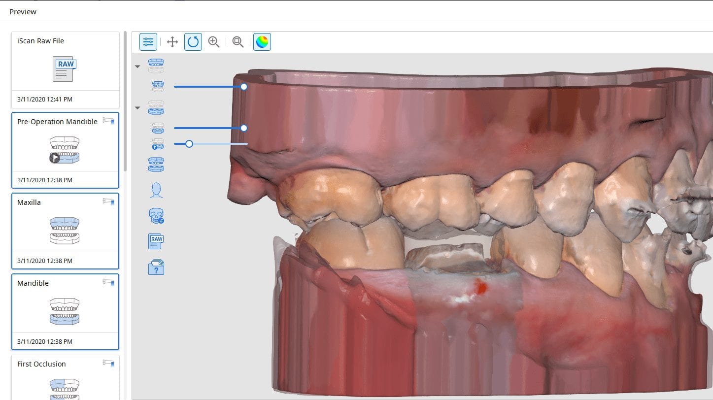
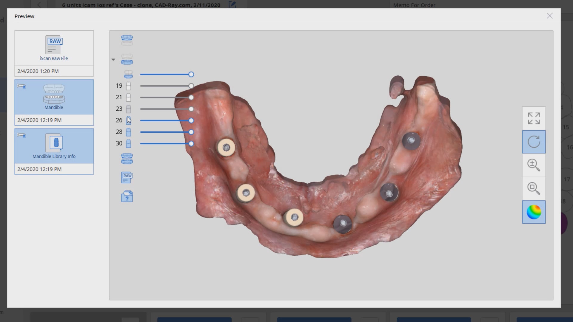
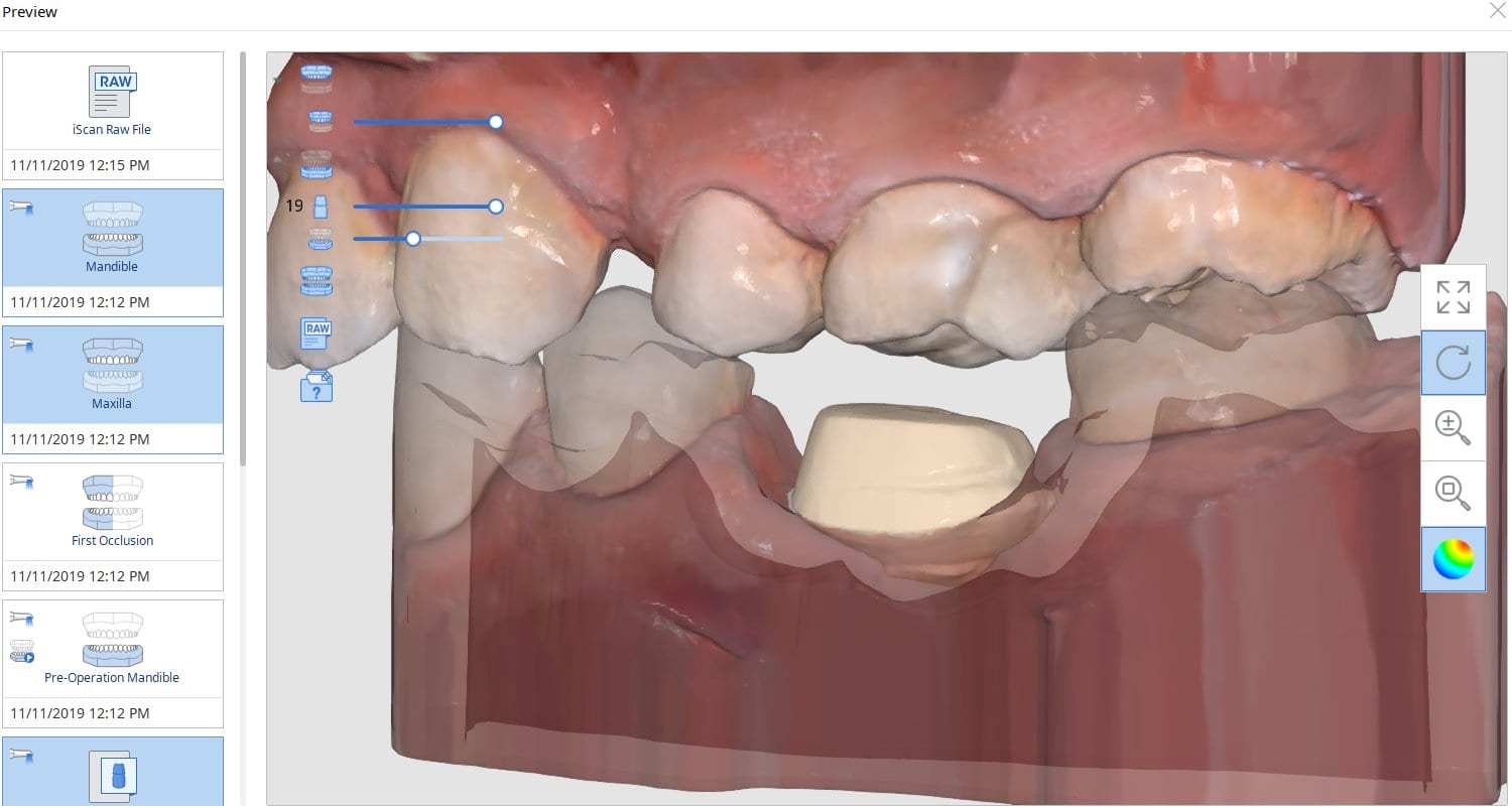
To date, the literature and research clearly points out that full arch scans with edentulous arches are prone to inaccuracies. That’s because we have never had a way to measure and verify models while scanning. There are two features unique to the Medit i500, namely the reliability map and the artificial intelligent implant suprastructure identification system. Individually, they do not provide much information with regards to accuracy, but if you understand how they work, you can utilize them to assess accuracy while you are scanning edentulous arches.
We proved the validity of this concept by utilizing these two features by incorporating a scan from the imetric Icam4D scanner and merging its data with the IOS to render a perfect match. Details are posted for our users in the Imaging Implants Section of our tutorial liabrary
This is a preview of a single unit case that was scanned using the Artificial Implant Suprastructure Identification System of the Medit Software. To see the full case follow this link
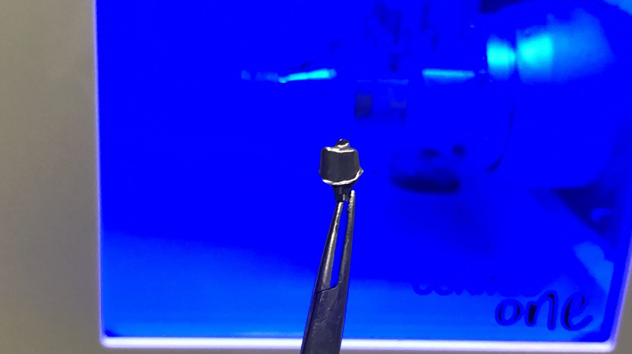
Hydroflouric Acid Etched Treated Scanbody Surface makes Intra-Oral Scanning much easier for all dental scanners. Apply a coat of HF for a mere 10 seconds and rinse off.
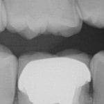
In this clinical case a patient lost a pre-existing crown. The remaining tooth structure had recurrent decay and a new crown was warranted.
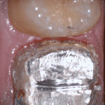
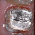
After anesthesia was administered, the clearance from opposing dentition was assessed. The preparation was reduced to accommodate the necessary thickness of the material.
Once adequate clearance was achieved an Optragate was placed and an isolite was used to isolate the area. The preparation was scanned and then the lower arch was captured. The buccal bite was then taken to along the arches together
With Meditlink software, you have the option of designing the case yourself or sending it off to your partnered lab. The following video shows what happens to your case once the lab downloads the case
In this particular case, we designed our own crown and milled it with the coritec one milling machine
Once the amber lithium disilicate material was milled, its for was verified clinically. The crown was then crystallized and seated with NX3 resin cement
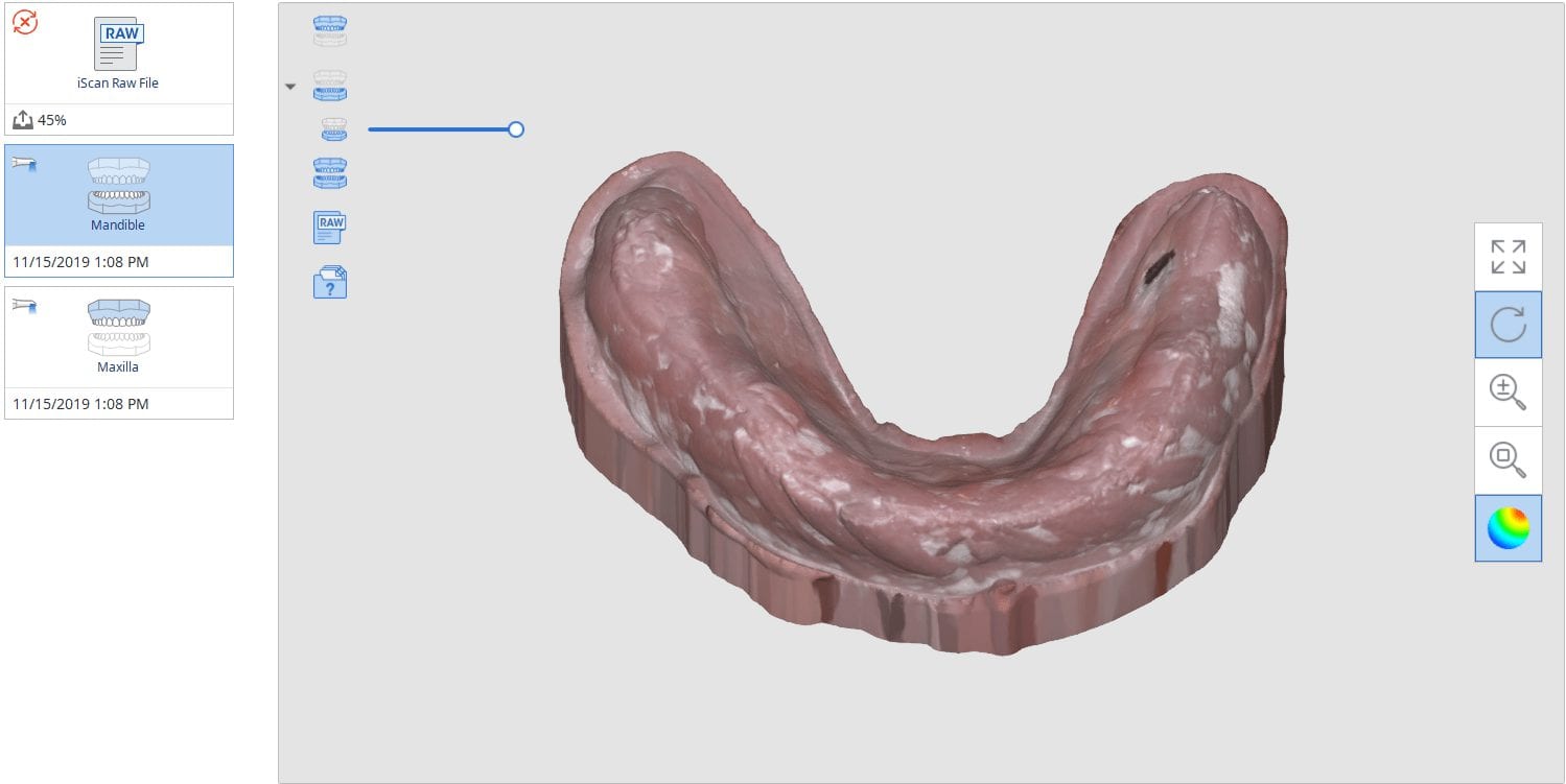
In this video we show how to you can digitally pour up the intaglio of a denture scan with the medit software where you scan in the impression mode, “reverse normal”, process the case and the add a base to it. You can then immediately send it to a printer
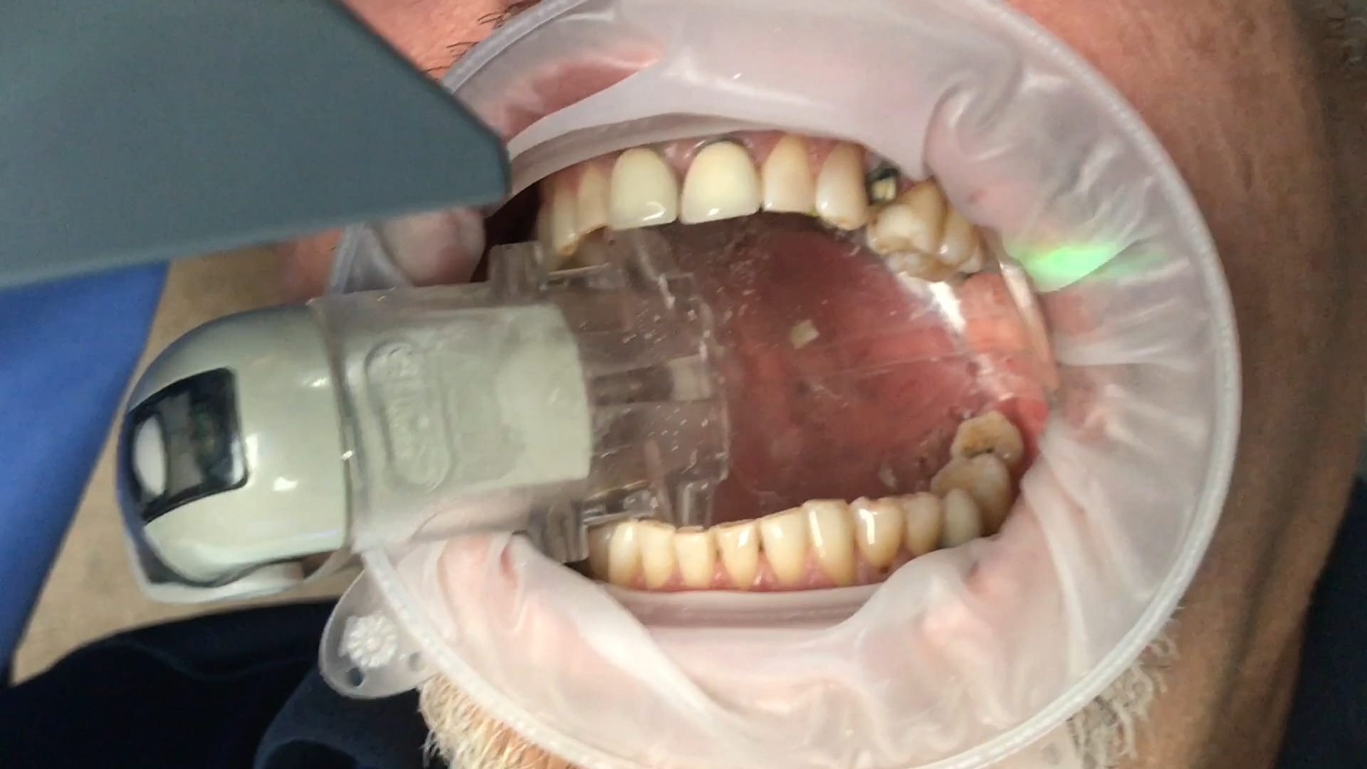
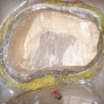
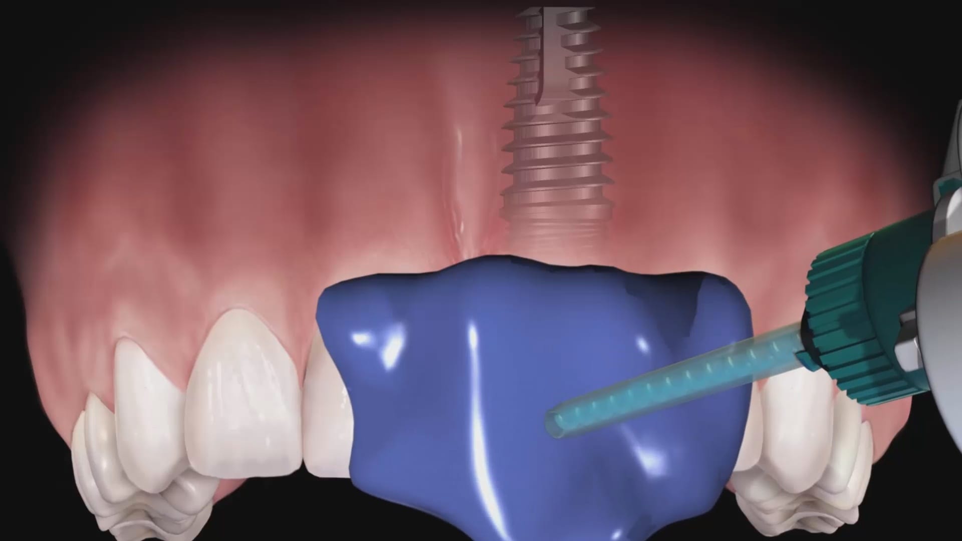
Taking impressions, digital or analog way, was one of the greatest hassles in implant dentistry. we can now image the margins of the implant suprastrucure OUTSIDE the mouth, merge it with the intra-oral condition, and mark the margins on the digital file as opposed to getting hemostasis and tissue retraction in difficult situations..
medit i500 takes one of the most complex and error prone situations and simplifies it, whether you send the case to the lab or do in office restorations.
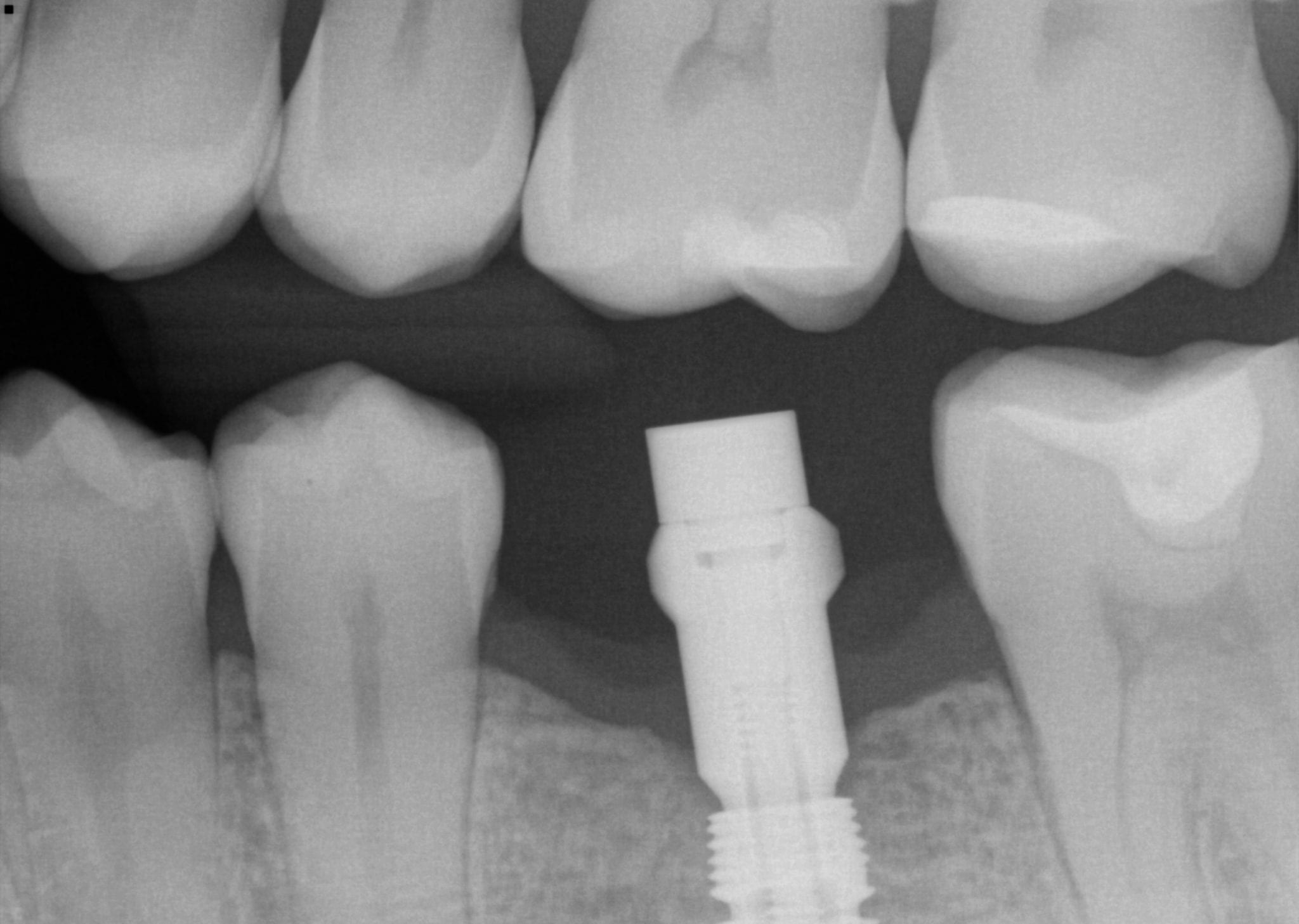
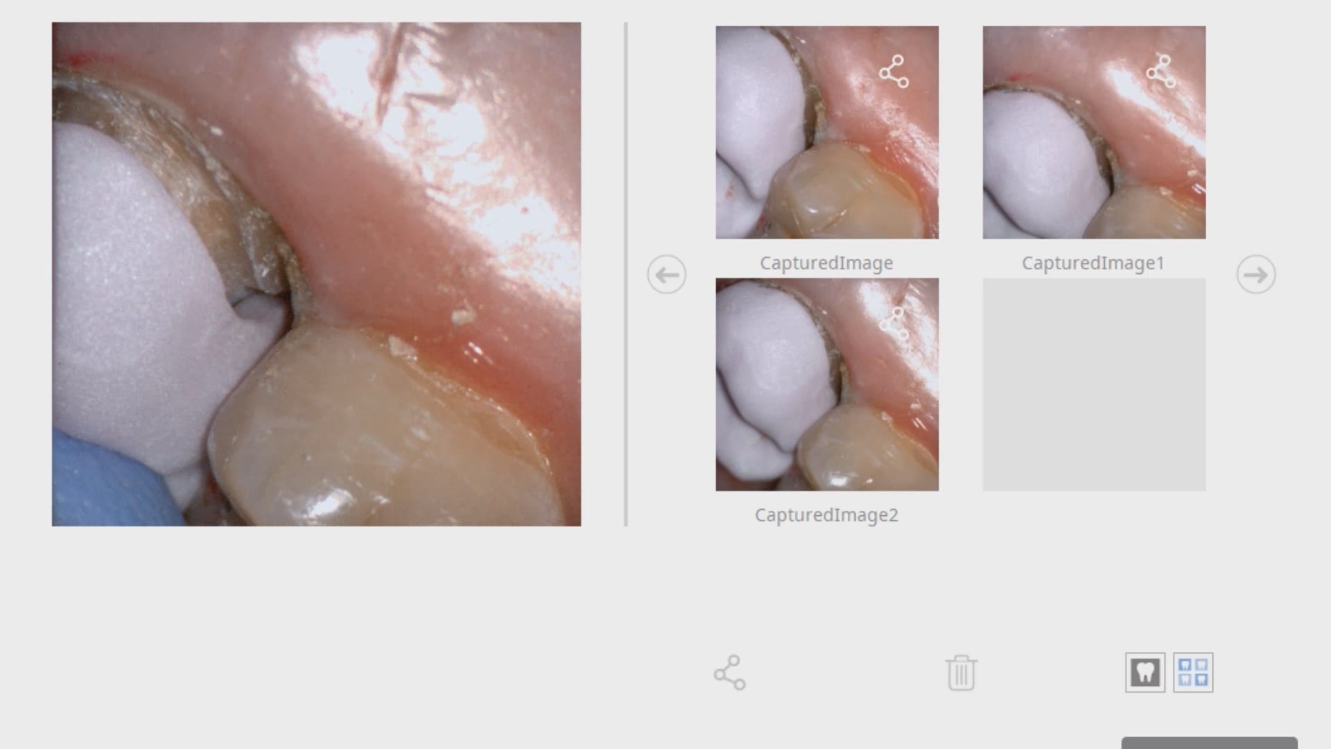
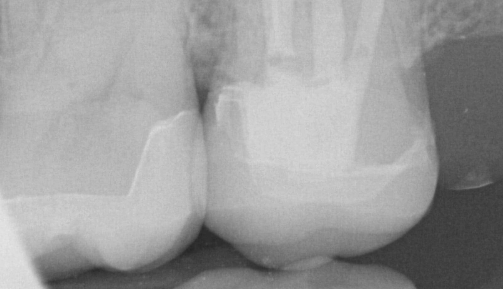
In this video, we show a recall of an implant restored with a scanbody. When the implant was initially placed, a scanbody was seated and an X-ray was taken to verify that it was seated. The titanium scanbody allows for visualization of seat. A peek scanbody does have a metal carrier but it is confusing to some users to verify that it is engaged with the fixture.
The proper placement of this biomax implant, followed by ideal contouring of tissue and bone around the head of the fixture, allowed for enough “running room” to create the desired emergence profile
With analog dental impressions, it is imparative to separate the gum tissue from tooth structure and to create a trough for flash for dye work. This is not the case with the intra-oral scanner by Medit. All you need to do is displace the tissue so you have a clear line of site to the margins, and you just need to be flush. You don’t need flash like you do with stone work
Dental implant surgery and restorations were the most risky procedures just 10 years ago. They were also the most profitable, but also carried the largest liability and the most significant surgical and restorative lab costs. A simple error introduced in the restorative process could easily eliminate the profit margin and a more significant mishap can create an undesirable outcome
We have seen dramatic changes in implant surgery where both the cost of the surgical stent and the fixture placement have reduced to the point where fully guided surgery is now the norm as they speed up the surgery and normalize the accuracy of placement across a broad range of practitioners with varying levels of experience. We are now seeing the same type of effect on the restorative side of the implant treatment, where digital dentistry is greatly reducing costs and errors.
With permission from blueskybio.com, we captured some key elements with analog impressions to highlight potential errors that can be introduced. The full video can be seen here:
The common sources of errors that someone can introduce are:
The inherent nature of impression material that can distort during the impression step
The angulation of the impression abutment may prevent it from seating all the way or may bind on the adjacent teeth making it difficult to capture an accurate impression
The size of the impression abutment can usually block access to the contours of the adjacent teeth where the pvs material does not capture the detail needed to generate good contacts and emergence profiles
Not securing the implant analog with the abutment in the impression material so that it does not distort or vibrate out of its position while pouring stone into the PVS material
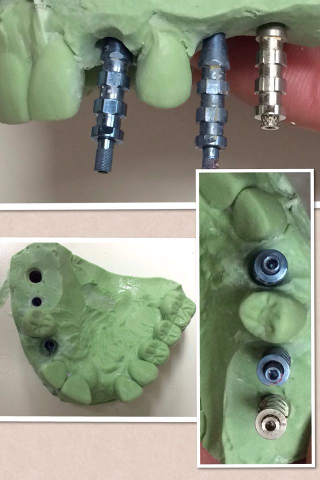
With multiple implant, the problems can compound exponentially if the implants do not draw well together with complications ranging from locking the tray in the patient’s mouth accidentally or distorting the impression material enough when removing it where you decrease the accuracy. Some practitioners prefer to do this in multiple steps, correcting angulation and collisions with custom abutments and several impressions
Fortunately, in this impression of 3 implants that were placed with a guided, the impression abutments are parallel to each other but just a few degrees in either direction, you can have multiple collisions of the abutments with the adjacent teeth or in between the abutment themselves. What a scanbody does is it allows for the optical scan of a geometric shape that helps CAD software identify the exact location of an implant fixture, its timing, and its relationship to the arch form.
It has significant advantages as there is no distortion of the impression material. Moreover, you can capture all the detail of the adjacent teeth before you place the scanbody in the mouth. This dramatically reduces the errors and adjustments you will need to make during the seat appointment.
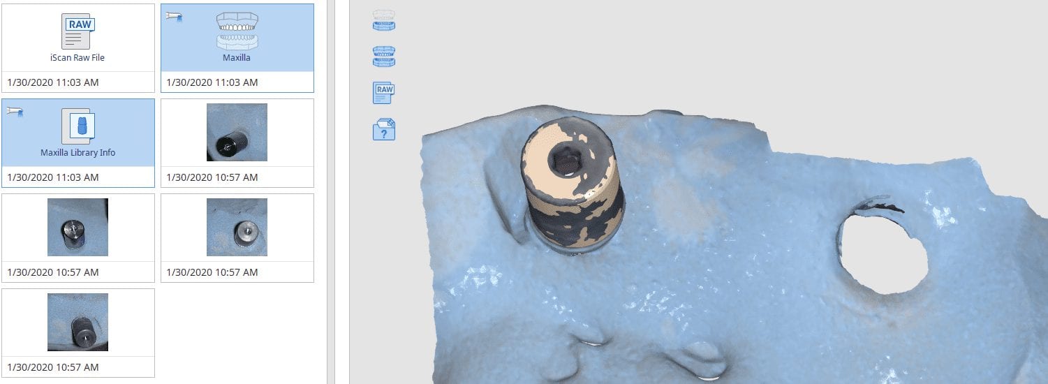
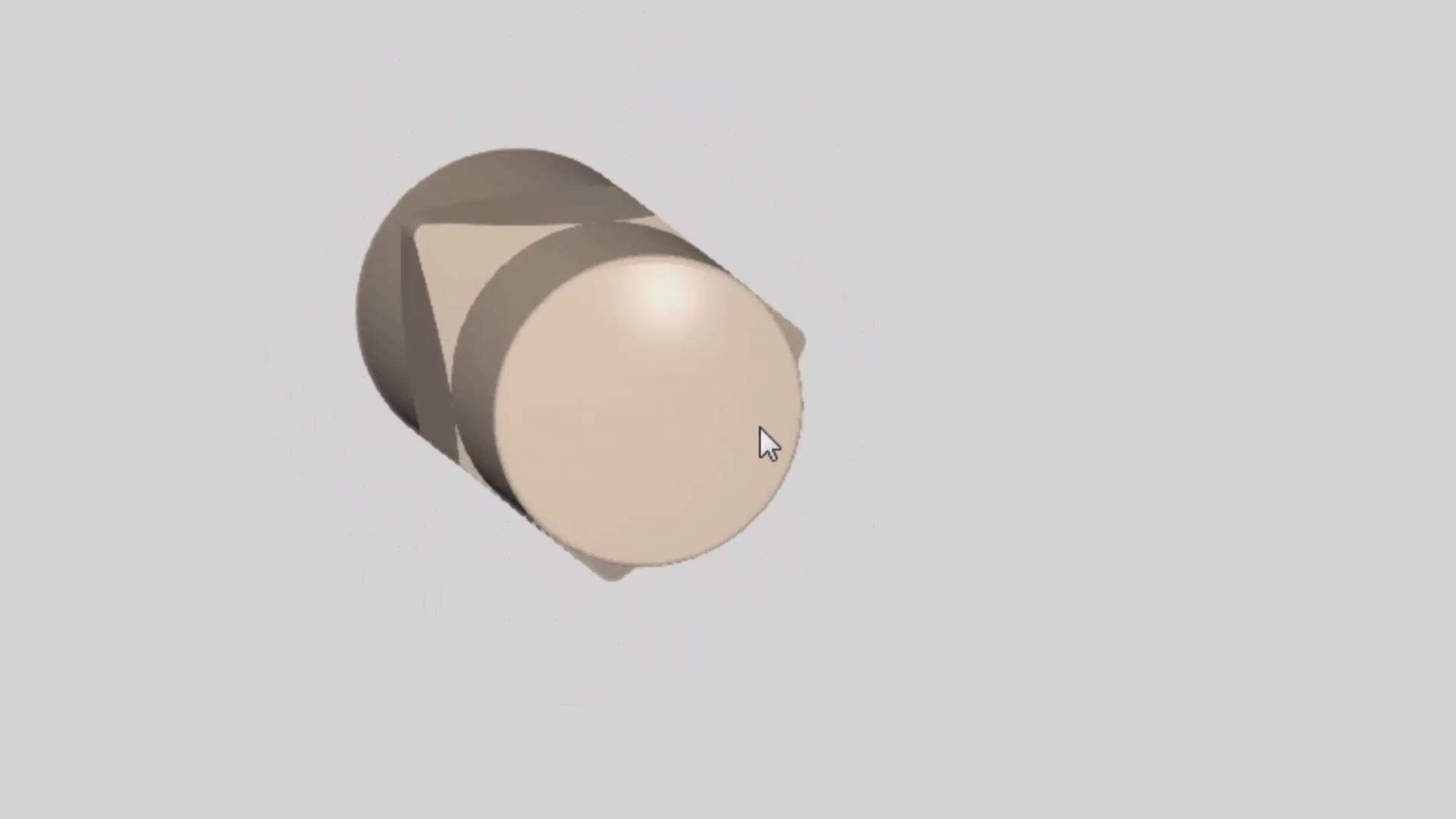
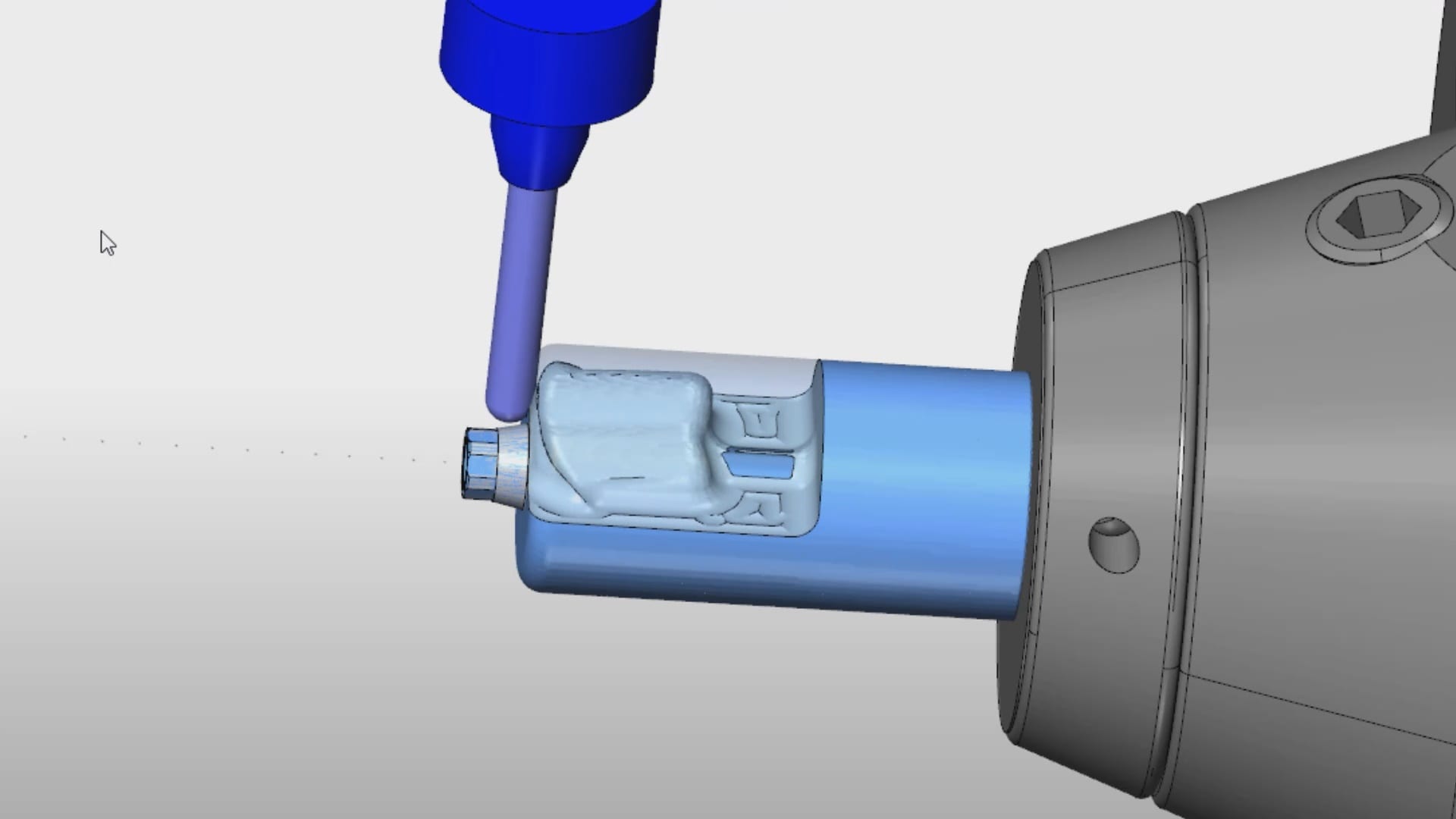
This video shows you the contour or the shape of a specific scanbdoy. There are many manufacturers that produce the scanbodies for a variety of fixtures with different geometries. Ideally, you use a titanium based one so that you can take an x-ray to make sure it is seated all the way. A frequent cause for error with digital impression is that you bind on tissue of bone which block you form seating all the way.
Once you have scanned the pertinent information, you can then take the digital models to CAD software where the location of the fixture is identified digitally and you can design the restoration of your choice. This can be titanium abutment or a tibase that retrofits ceramic material like emax or zirconia. The following video demonstrates how you identify the scanbody in exocad and proceed with a sample design.
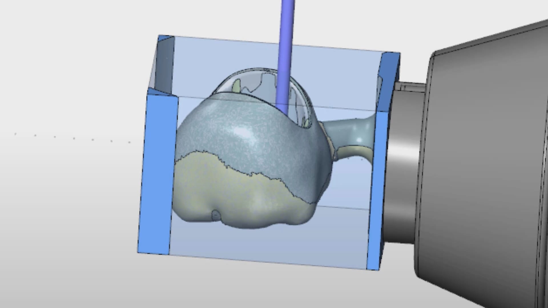
Once the design is completed, you can outsource the fabrication of the abutment and/or the crown. There are many machines that you can use to fabricate the titanium abutment. Please note that the milling machines do not mill the connection. The connection to the implant comes pre-manufactured. The cylindrical block is milled to shape. The cad software also maintains the relationship of the abutment to the crown so that they retrofit to each other.
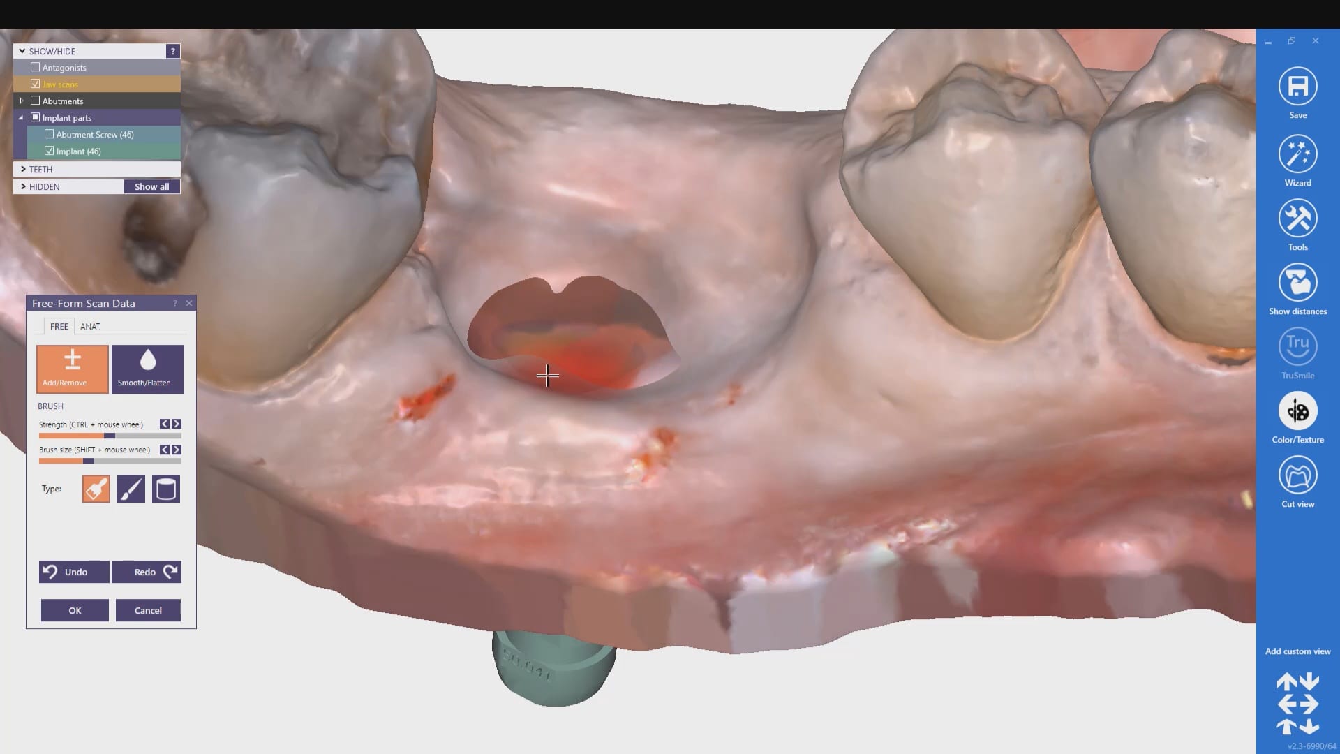
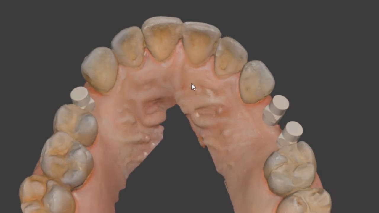
Now imagine if you had multiple implants that did not draw together? What’s great about digital dentistry and how we use the Medit i500 here is how we utilize a single scanbody to capture the location of 3 fixtures. One thing we emphasize at CAD-Ray is how digital impression allow you to create models over time and out of sequence. They are also editable and additive. In the subsequent video we demonstrate how you can capture segments at a time, which can greatly help when you have implant abutments colliding into each other.
You can place the scanbdoy in one location, scan it, digitally protect the area, remove the scanbody, place it into another location and image it at the new location, dramatically overcoming all the obstacles described above
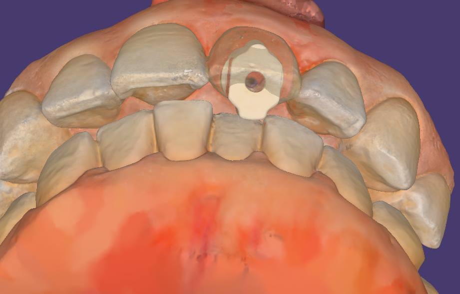
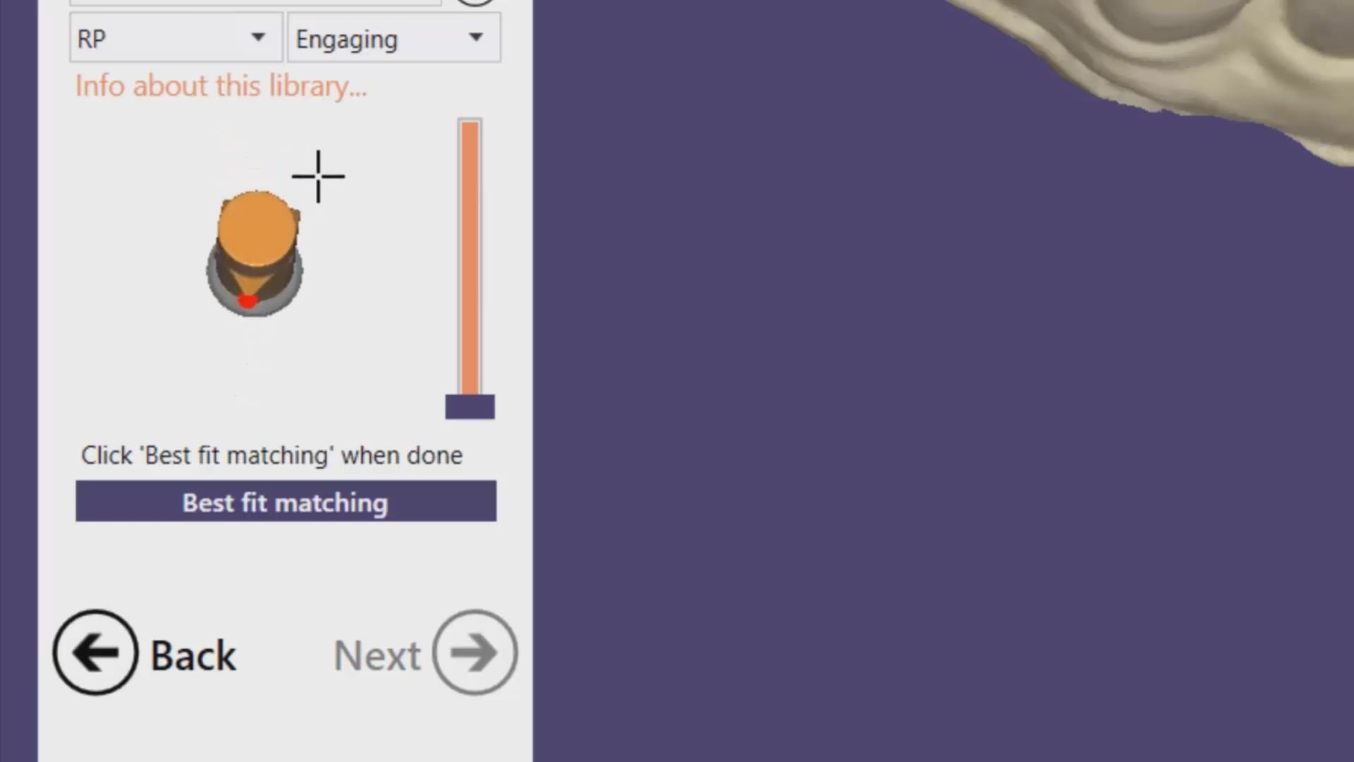
Now for the greatest news and the largest advancement in digital dentistry in a decade! Medit i500 has launched the Artificial Intelligent Implant Identification System where the software automatically recognizes these scanbody and lets you skip dozens of steps to get to the immediate design steps of the restoration. The algorithm utilized to match the digital scanbody to the physical one is proprietary to Medit and is unparalleled in its accuracy. A lot of the guess work and inherent errors in the digital platforms are reduced with this software which is a contrasting as the difference between analog and digital impressions.
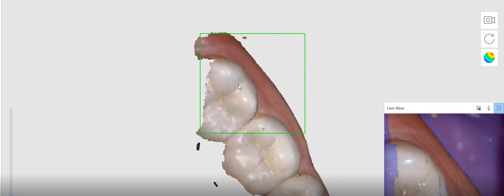
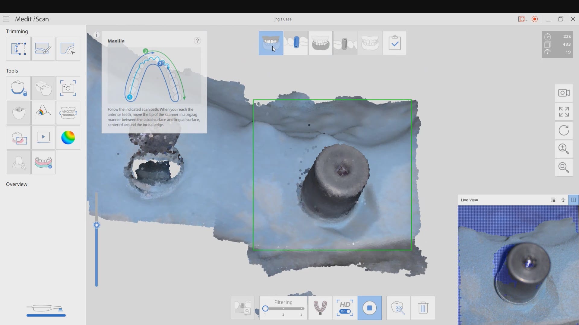
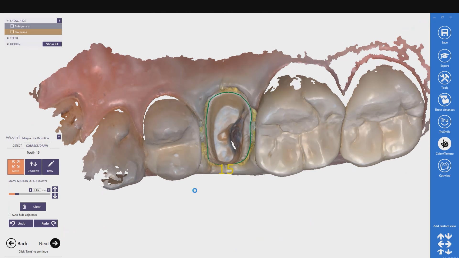
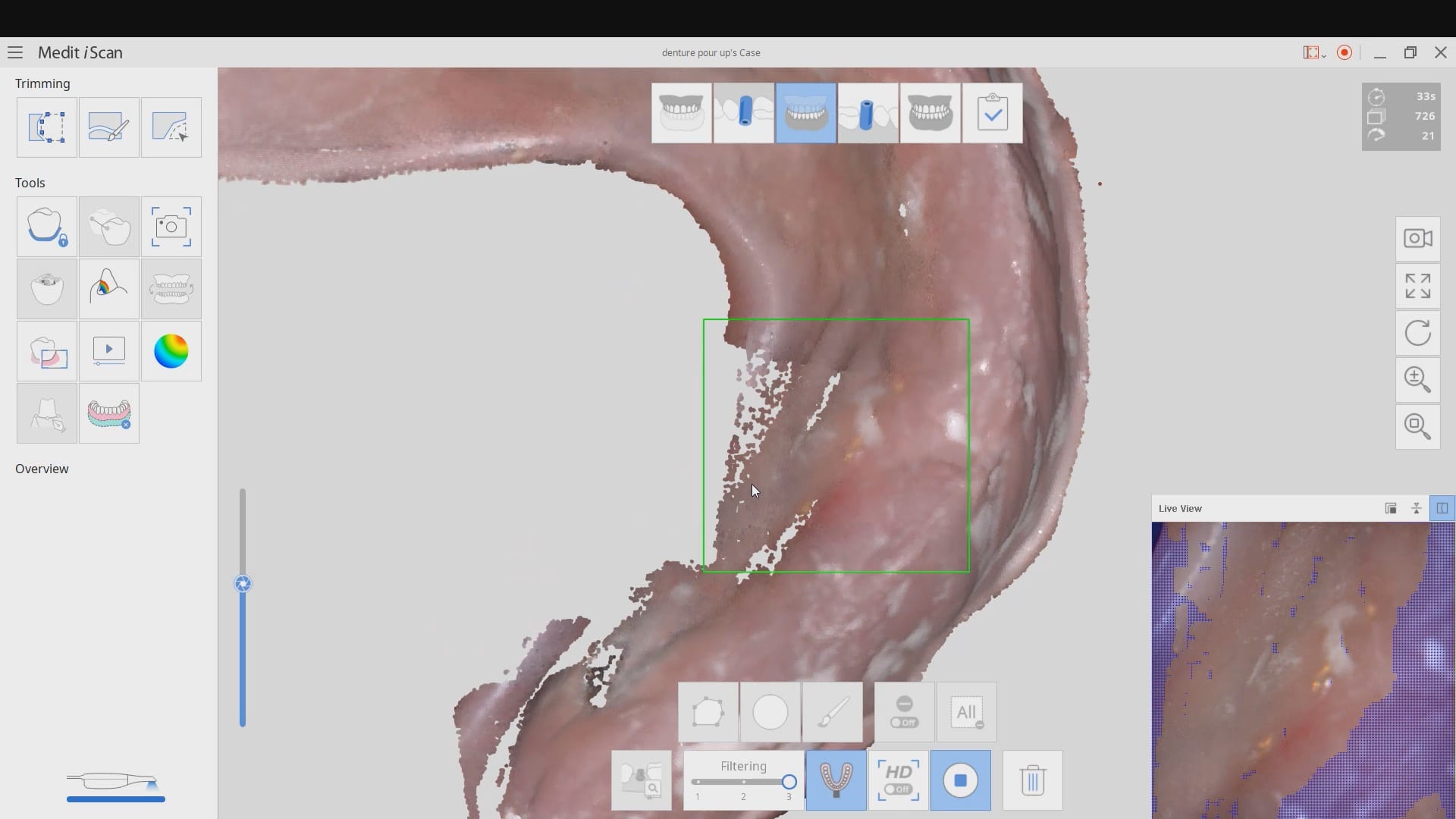
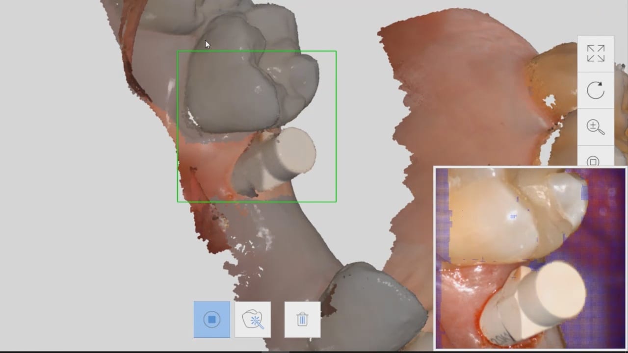
When you have preops that you are trying to stitch to preps in medit, and this could also include relating scanbodies to arches as well, you need enough data that is redundant in both catalog boxes
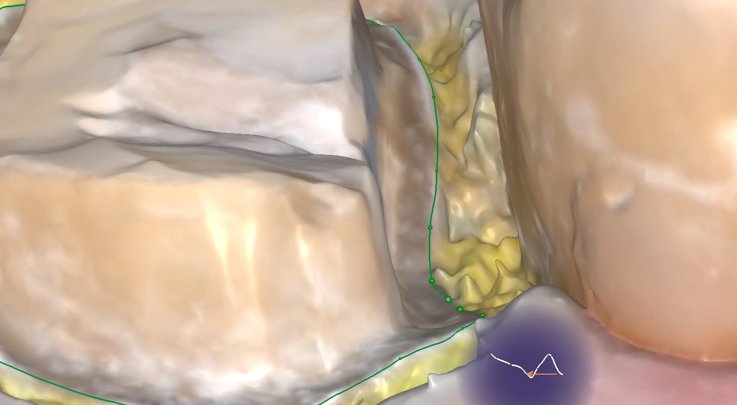
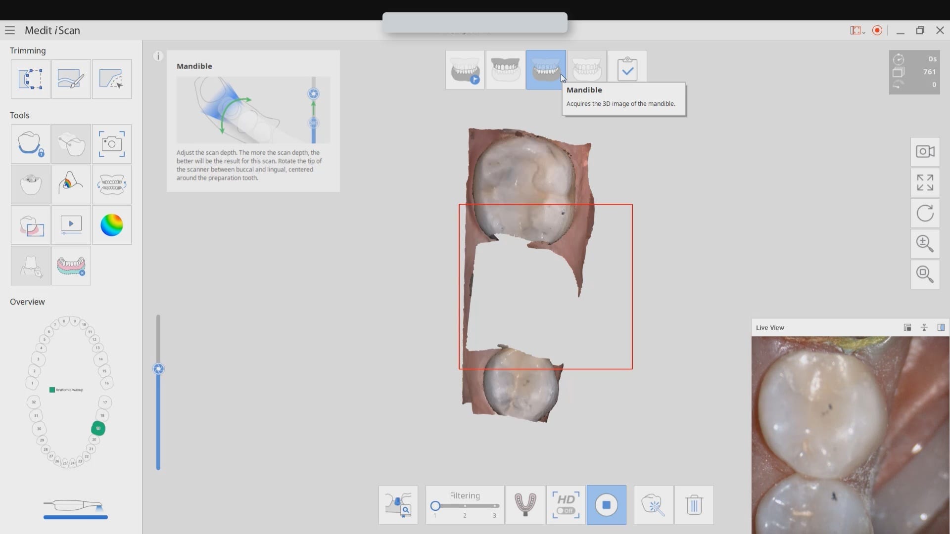
if you watch this video carefully, you can see how i over trimmed the mesial part of the equation and even though the camera is active, it is not acquiring images. you can see the red box.
once i move the camera to the distal molar, the acquisition starts because the molar has more data points than the premolar and the software / camera recognized the area and started to acquire images.
understanding this will unlock a lot of complicated cases and make the easier for you