I purchased the Medit i500 from Cad-Ray December 2018. I couldn’t be happier with the scanner. The improvements Medit has made over the last 10 months are nothing short of astounding! I can’t imaging what they’ll come up with next.
As for Cad-Ray...read moreI purchased the Medit i500 from Cad-Ray December 2018. I couldn’t be happier with the scanner. The improvements Medit has made over the last 10 months are nothing short of astounding! I can’t imaging what they’ll come up with next.
As for Cad-Ray, their support has been second to none. Never have I experienced the kind of attention and help from any other company. Wether it’s with help installing, computer hardware issues or technical help they respond IMMEDIATELY!
Armen is also a huge reason why I chose Cad-Ray. No one selling a product has helped me more evolve my scanning technique. He’s quick to respond to questions and issues I feel his service is a huge reason why to buy from CAD-RAY.read less - 10/09/2019
These guys are the best. They provide so much help and insight with the Medit. I can't say enough great things about them and their continued support. I truly appreciate everything!! - 6/16/2020
Jay Siddiqui
Amazing support and install, Jesse went through everything and made sure I was comfortable with my equipment before leaving. He also introduced me to the world of anodizing and now I am hooked! Highly recommend them for any tech you may need. - 8/23/2022
Mehryar Ebrahimi
Great costumer service. I needed a part for my i700 and they were able to ship overnight. No down time. - 5/06/2022
Jeff Muszynski
Fantastic customer service - 6/19/2020
Alec Keon
I was on the fence on getting a scanner for years and finally pulled the trigger. CAD-Ray's support and knowledge has made this one of the best investments in my practice to date. When I spoke with Damien on the phone about my options he literally sa...read moreI was on the fence on getting a scanner for years and finally pulled the trigger. CAD-Ray's support and knowledge has made this one of the best investments in my practice to date. When I spoke with Damien on the phone about my options he literally saved me thousands after figuring out what my exact needs were. I went with the Medit i600, MSI laptop and 3D dental systems cart. The final product looks and feels as premium as it gets.read less - 2/21/2024
Tony Cascino
I just purchased the CAD-Ray unit at Chicago Mid Winter meeting. We have used it for single crowns so far and have been very pleased. Nick was my sales contact and he has helped a great deal with some of our 'learning curve " issues. I looked at a nu...read moreI just purchased the CAD-Ray unit at Chicago Mid Winter meeting. We have used it for single crowns so far and have been very pleased. Nick was my sales contact and he has helped a great deal with some of our 'learning curve " issues. I looked at a number of scanners and felt CAD-Ray was the best-two of the labs I use also feel it is the best scanner.read less - 5/12/2020
H C
I got my 3Dshape scanner, great support , my training with Destany was excellent. Great team!! - 2/15/2024
Emerson Gower
Nothing but great things to say about Cad-Ray! Excellent customer support from Laura after the purchase of our Medit i500 and the cart from Damien. I’ve been very impressed with the Medit in restoring crown and bridge, as well as fixed hybrids, and...read moreNothing but great things to say about Cad-Ray! Excellent customer support from Laura after the purchase of our Medit i500 and the cart from Damien. I’ve been very impressed with the Medit in restoring crown and bridge, as well as fixed hybrids, and learning more of its capabilities each day. We have intentions to buy a second Medit shortly and will definitely be using Cad-ray again.read less - 12/13/2021
Ponciano Melo
If your planning to buy dental oral scanner look for Jon. He will give you a great deal. He is very friendly and knowledgeable about the advantage of Medit I500. AGAIN, Don't forget to look for Jon for your next oral scanner. I highly recommend this ...read moreIf your planning to buy dental oral scanner look for Jon. He will give you a great deal. He is very friendly and knowledgeable about the advantage of Medit I500. AGAIN, Don't forget to look for Jon for your next oral scanner. I highly recommend this guy.read less - 1/09/2021
Dr. Terry Zervos, DDS,PA.
Today I had to order new tips and Laura was EXTREMELY helpful, Cad-Ray has all the products you need for digital dentistry and they do Education, if you buy Medit scanner from them they include 12 CE training course. Cant just buy a Lamborghini you h...read moreToday I had to order new tips and Laura was EXTREMELY helpful, Cad-Ray has all the products you need for digital dentistry and they do Education, if you buy Medit scanner from them they include 12 CE training course. Cant just buy a Lamborghini you have to learn how to drive it!read less - 7/02/2020
Sherif Gabr
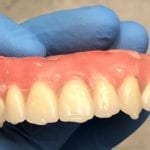
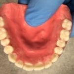
I have been suing the Medit i500 scanner for a little over 2 months now and I have had great success. I have used it for implant cases, immediate dentures and single unit crowns.
What I like the most is that the software is continuously improving ...read moreI have been suing the Medit i500 scanner for a little over 2 months now and I have had great success. I have used it for implant cases, immediate dentures and single unit crowns.
What I like the most is that the software is continuously improving and adding new features.
You really can not ask for more than that! Great product, excellent support and a software development team that listens to their customers feedback!
Very happy with my purchase!!!read less - 2/26/2020
Great product and company. all the help and support you need on their website and Facebook group. recommended them to many of my colleagues and bragged to other reps about how good my deal was compared to what they were offering. - 6/16/2020
Carter Weber
I had a great experience with CAD RAY. I was lucky enough to have Frank DeLuca come down to my office to demo the Medit I700. Needless to say, we were in love with the technology and the great hands on demo. CAD RAY overnighted me the scanner and we ...read moreI had a great experience with CAD RAY. I was lucky enough to have Frank DeLuca come down to my office to demo the Medit I700. Needless to say, we were in love with the technology and the great hands on demo. CAD RAY overnighted me the scanner and we were off to the races. Any time we have had a technical question, Frank has personal helped me or put me in touch with one of his colleagues if he wasn’t available. All around, it was as 5 star experience!read less - 12/16/2021
Obdulia Rondon
Thanks for delivering amazing courses. Always thinking beyond dentistry. Thanks for sharing all so selflessly. - 11/13/2022
Jennifer Ebner
After using the medit i500 scanner at an office as an employee, I purchased it from Cad-ray,com specifically because of their good reviews and their large, concise training library of videos. I've used CEREC as an instructor at a dental school and bo...read moreAfter using the medit i500 scanner at an office as an employee, I purchased it from Cad-ray,com specifically because of their good reviews and their large, concise training library of videos. I've used CEREC as an instructor at a dental school and bought a used Planscan, Planmill for my private office. Both were hard to learn and the fees and cost associated with training were a bitter pill to swallow after the costs to purchase. The ease of seating restoration was instant. The scanning learning curve is quick. I have easily added occlusal guard scanning, and implant scanning and will be trying a digital denture soon.
The purchase was easy, the product came quickly and the set-up videos guided me through very necessary adjustments to my Laptop I never knew I needed. Learning the new features with each FREE update is a treat. The DIY option was an extra bonus as the $2000 rebate came without having to ask for it. Cad-ray has delivered more than I expected with the purchase of the fantastic Mediti500 scanner.
I've included my cart set up. purchased from Amazon for $68. Its stable, has room for the necessities. I've taken it home and back to the office half a dozen times and it transports the scanner safely. It also keeps the cords from being run over. I haven't taken the included 2 day course but look forward too it after Social Distancing mandates are lifted.read less - 4/25/2020
Excellent customer service and support. Kaila was extremely pleasant and professional over the phone. She sent us the replacement part in a timely fashion. Will recommend this product and their business to fellow colleagues. Thanks again! - 12/06/2021
Anthony Vu
If you are looking to buy a Medit, you shouldn't look anywhere else to buy it. My Medit i700 was having issues on a Friday and I was able to get Heather from Cad-Ray to troubleshoot the issue. She remoted into my computer to try and troubleshoot the ...read moreIf you are looking to buy a Medit, you shouldn't look anywhere else to buy it. My Medit i700 was having issues on a Friday and I was able to get Heather from Cad-Ray to troubleshoot the issue. She remoted into my computer to try and troubleshoot the issue and helped with getting Medit on board as well. Once it was confirmed it was a hardware issue, I got sent a BRAND NEW Medit i700 OVERNIGHT.Can you believe that? Service and warranty that Cad-Ray offers is really TOP NOTCH.Highly Recommend Cad-Ray for all things MEDIT. Thank you Heather from Cad-Ray for all your help!!!read less - 2/02/2022
Krystyna
I recently purchased Medit scanner and my assistant and I went through training with Andy. He was great, knowledgeable and patient with us. Customer service is great! - 2/05/2023
Levy Do
I'm a repeat customer because Cad-Ray's customer service is fast, efficient, and no nonsense. The classes offered for training for particularly for the Medit is awesome and it comes included which is phenomenal. All the classes that I've gotten to at...read moreI'm a repeat customer because Cad-Ray's customer service is fast, efficient, and no nonsense. The classes offered for training for particularly for the Medit is awesome and it comes included which is phenomenal. All the classes that I've gotten to attend so far has been well organized and I left learning very practical things. Remote support team solves my problem right then and there. Recently I had an issue, and instead of me talking to a sales rep who doesn't know what to do, Kaila remoted in and got it fixed just like that. Thank you and great job guys!read less - 4/19/2022
Robin Thoman
Instant support, nice people at Cad-Ray but LOTS of trouble getting CIT 12m same-as-cash approval as offered. CIT fumbled around for 7d in finding credit report. Eventually fed up with inactivity or support after lifting Equifax credit freeze and d...read moreInstant support, nice people at Cad-Ray but LOTS of trouble getting CIT 12m same-as-cash approval as offered. CIT fumbled around for 7d in finding credit report. Eventually fed up with inactivity or support after lifting Equifax credit freeze and directed to Experian quagmire of automated phone calling tree.read less - 1/09/2021
David Weber
Much like dentistry is not a commodity, CAD-RAY's service is not a commodity. What CAD-RAY does so well is not just sell pieces of technology affordably and smoothly, but provides service, training, and insight so these tools can be used meaningfully...read moreMuch like dentistry is not a commodity, CAD-RAY's service is not a commodity. What CAD-RAY does so well is not just sell pieces of technology affordably and smoothly, but provides service, training, and insight so these tools can be used meaningfully and profitably.read less - 12/12/2022
Wes Buchman
Used CAD-Ray for my Medit scanner purchase, training, and assistance and have had zero problems. They are so quick to respond to inquiries and helping with any minor issues (which have been very minimal). Highly recommend working with this company - 8/27/2021
Al Villalobos
Great scanner at a good price...Excellent customer service . I never want to take a conventional impression again! Best upgrade to my office in years. - 11/16/2021
Aaron S
Great ongoing support and customer assistance. Been working with Frank for years, even before cad ray. Always there for any help i ever need. Cad ray support is like no other. - 1/26/2023
Gary Benson
Our orthodontic office is new to scanning and printing, but CAD-Ray, Laura, Medit, and SprintRay have made the whole transition a huge win. Our first scan and print was cleaner than any traditional impression/pour up we've ever produced. On our first...read moreOur orthodontic office is new to scanning and printing, but CAD-Ray, Laura, Medit, and SprintRay have made the whole transition a huge win. Our first scan and print was cleaner than any traditional impression/pour up we've ever produced. On our first full clinic day, we scanned 14 arches and managed to stay on schedule! We were waiting for this technology to be affordable, fast, accurate, and reliable, and we can now say we are there. Thanks for all your help and ongoing support.read less - 6/25/2021
fantastic support, I always ask random, specific to me, could be found on a training video, questions and they always quickly tell me how to fix my problem. - 6/16/2020
jeremiah choi
Never had customer care like Cad-Ray, you can't go wrong purchasing through them. Trios is a great scanner. All the reps at Cad-Ray are very knowledgeable and helpful and will make sure you are up and running smoothly. Above and beyond customer serv...read moreNever had customer care like Cad-Ray, you can't go wrong purchasing through them. Trios is a great scanner. All the reps at Cad-Ray are very knowledgeable and helpful and will make sure you are up and running smoothly. Above and beyond customer service.read less - 8/27/2022
Highly recommended. Ericka help me through all the process when we were having some trouble with our scanner. The help was super fast and secure. She answered all our questions and made sure our scanner were working perfectly. - 4/29/2025
Ryan Buckwalter
Couldn't have had a better experience. The training was excellent, and they've been great to work with. I recently had an issue that required a warranty claim. The process was super easy, and completely hassle free. In fact, I'm still in shock at...read moreCouldn't have had a better experience. The training was excellent, and they've been great to work with. I recently had an issue that required a warranty claim. The process was super easy, and completely hassle free. In fact, I'm still in shock at how great they were about the whole thing. I would (and do) highly recommend this company.read less - 2/09/2021
Evan Bedell
Laura has always been so helpful with the medit when we needed assistance or resources. The training she provided the office was invaluable! She is quick to respond whenever we reach out. 13/10 - would recommend her to anyone looking to get a medit ...read moreLaura has always been so helpful with the medit when we needed assistance or resources. The training she provided the office was invaluable! She is quick to respond whenever we reach out. 13/10 - would recommend her to anyone looking to get a medit scanner.read less - 12/16/2021
Sonrisas Dental
Support was our main concern, and we chose very carefully. Frank is 100% every step of the way - 1/25/2023
Kallen Wheeler
I always have enjoyed working with Cad-ray. Customer service is always on-point! - 5/25/2022
Kyle Coffin
Bought a medit 6 months ago and customer service has been nothing short of amazing. Always very responsive and helpful. Great scanner, too! - 6/16/2020
Mayoor Patel
Kaila is awesome with training and her customer service skills. Enjoy learning from her... Product (scanner) so far loving it. - 12/02/2021
Jason Oh
Everyone at CAD Ray has been amazing. Glad I chose them for my Medit and Sprint Ray purchase. Our training with Kaila was awesome. Thank you - 1/04/2023
Eric Bailey
Couldn't be happier with the support I've gotten from these guys. Trouble-shooting a problem real time so you can call a patient and get them right back in with a solution is extremely hard customer service to match. Thanks a ton and no question wher...read moreCouldn't be happier with the support I've gotten from these guys. Trouble-shooting a problem real time so you can call a patient and get them right back in with a solution is extremely hard customer service to match. Thanks a ton and no question where I'll be going for any more purchases!read less - 10/06/2021
High quality scanner. Super fast. Have been happy with the support that Cad-Ray has offered. I really like the innovative technology that medit allows users to implement into their practice. - 10/13/2021
Purchased Medit in 2019. Bang for the buck best investment and will get you started in digital dentistry with ease. No monthly subscriptions and Cad-Ray support is amazing. No regrets. - 6/16/2020
I bought a i500 almost a year and a half ago. Sadly it ran into an issue with the cord after over a years use. Cad-ray was extremely quick to diagnose the issue and also send a replacement scanner. The quality and ease of scanning has been great! Als...read moreI bought a i500 almost a year and a half ago. Sadly it ran into an issue with the cord after over a years use. Cad-ray was extremely quick to diagnose the issue and also send a replacement scanner. The quality and ease of scanning has been great! Also very happy with the customer service.read less - 6/02/2022
Gregory Camfield
These guys are 1st in class service every time! - 7/08/2022
Daniel Eley
I just bought the new Medit i700. I placed the order on Friday, it shipped on Monday, and it arrived on Tuesday. So far it has been a great experience. They also provide a lot of quality videos for learning to use the scanner. - 5/05/2021
David Chong
Digital dentistry has changed my work flow for the better and could not imagine going back. So important that I have the support when things don't work as expected. CAD-Ray has been there every step and trust their expertise and knowledge! - 4/20/2022
Engy Hassan
Amazing customer service! Excellent on time feedback. Thank you Kaila - 12/08/2021
Cody Kriegel
Frank and the Cad Ray team have been nothing short of amazing. I continue to purchase digital equipment from Cad Ray because their support is unlike any in the dental industry. Frank has been instrumental in helping my team get the most out of our pr...read moreFrank and the Cad Ray team have been nothing short of amazing. I continue to purchase digital equipment from Cad Ray because their support is unlike any in the dental industry. Frank has been instrumental in helping my team get the most out of our products.read less - 1/25/2023
Preston Poole
Great company with even better customer service. Premier dental business with digital dentistry and scanners! - 11/03/2022
W Timothy Brooks
Excellent fast color scanner. A great improvement over my old proprietary scanner. Easy to learn software and great free technical support. - 6/18/2020
Extremely good customer service. From start to finish buying my Medit was flawless and they were very helpful in offering me information. When I got my scanner I had questions and my phone calls were returned immediately. They knew my name and guided...read moreExtremely good customer service. From start to finish buying my Medit was flawless and they were very helpful in offering me information. When I got my scanner I had questions and my phone calls were returned immediately. They knew my name and guided me through what I would need. Very impressed. Would recommend!read less - 2/02/2020
Shant Aharonian
Cad-ray has to be the best company to work with when it comes to digital dentistry solutions. Here are the reasons why:
1. Experience. Everyone in the company has extensive experience in dentistry. They have used all digital platforms and offer cust...read moreCad-ray has to be the best company to work with when it comes to digital dentistry solutions. Here are the reasons why:
1. Experience. Everyone in the company has extensive experience in dentistry. They have used all digital platforms and offer customers first hand experience.
2. Honesty. Based on their experience they share all the good/bad of different systems. They work with you to find a solution that works best for you. Not sell you the piece of the equipment that gives them the biggest commission.
3. Support. Cad-ray offers the missing piece of the dentist/digital manufacturer puzzle. Many other distributors sell you a piece of equipment but don’t have true day-to-day experience with that equipment. Cad-ray’s team openly share their expertise to help customers optimize their workflows with great technology.
4. Passion. The Cad-ray team is extremely passionate about their craft. They truly believe in what they have to offer.
I took Armen Mirzayan’s course on intraoral scanning and it was truly mind blowing. Armen’s insights will help any dentist optimize their craft. I purchased the full sprintray 3d printing ecosystem the help of Frank. I plan to purchase more equipment from cad-ray.
Also, Jesse is a genius in regards to all aspect of digital workflows. I’m truly grateful for this company and everyone who I’ve worked with so far.read less - 10/07/2022
Gabriel Joel
Medit i500 is an incredible scanner. I have experience with other types of scanners including IO and Desktop but this one is really impressive. It is blazing fast and takes beautiful scans. But more importantly is the company itself. Medit is an amaz...read moreMedit i500 is an incredible scanner. I have experience with other types of scanners including IO and Desktop but this one is really impressive. It is blazing fast and takes beautiful scans. But more importantly is the company itself. Medit is an amazing company and is constantly trying to improve. They are always on the cutting edge and releasing new improvements all the time. They are always LISTENING to the customers on how to improve the scanning experience and change accordingly. The customer service is second to none. I highly recommend this scanner but even more highly recommend considering buying the scanner as a result of the great company and PEOPLE that stand behind it.read less - 10/09/2019
Please, take a seat, you should not be standing while you watch this.
Artificial intelligence by Medit i500 now identifies the location of your scanbody but it also automatically launches all that proper information into CAD software for instant abutment designs. Make sure to watch both videos. Enjoy.
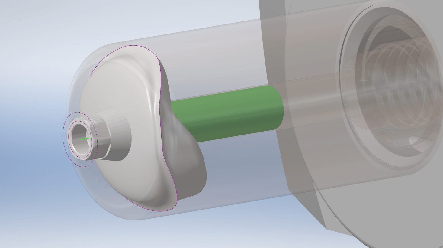
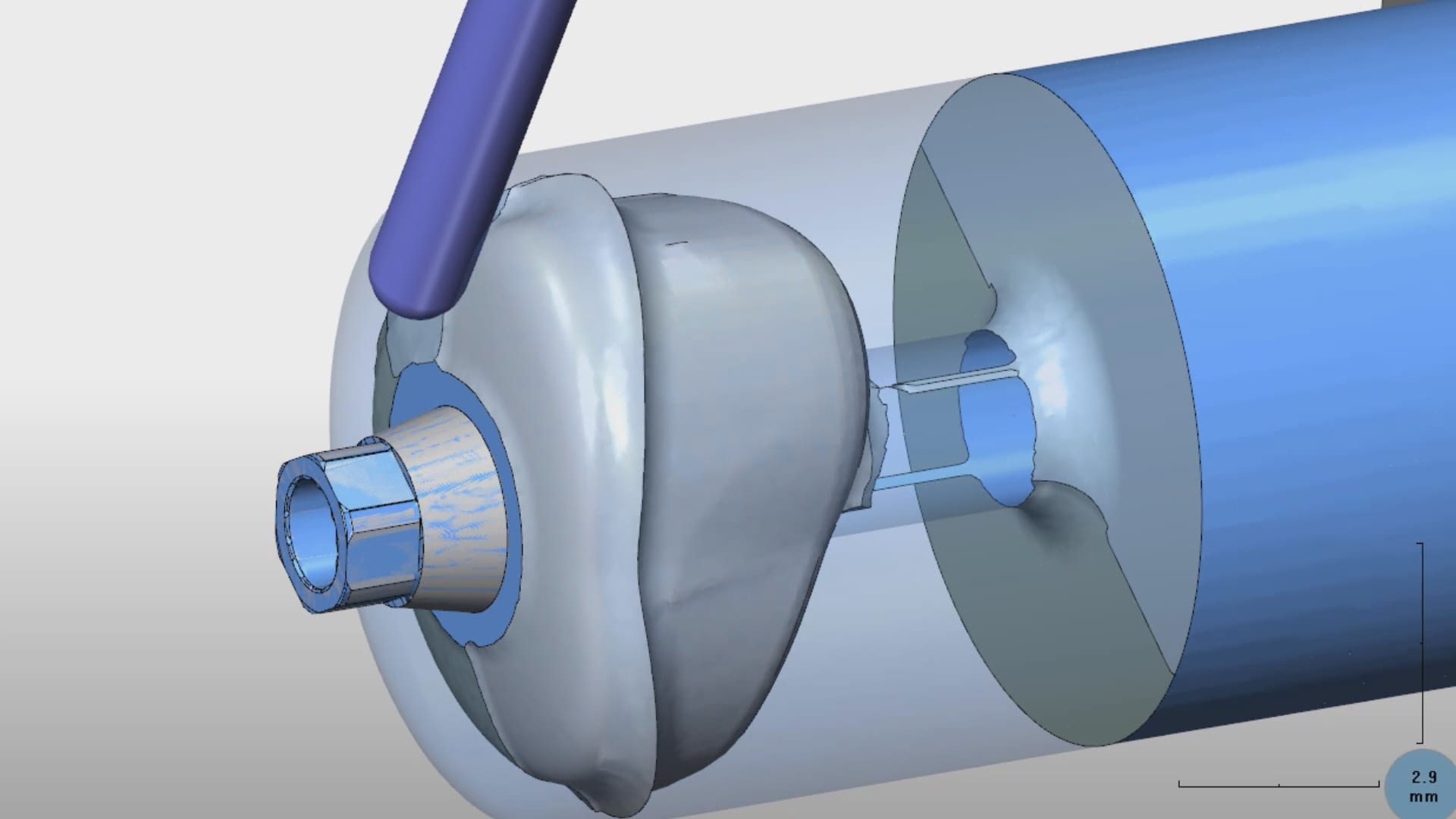
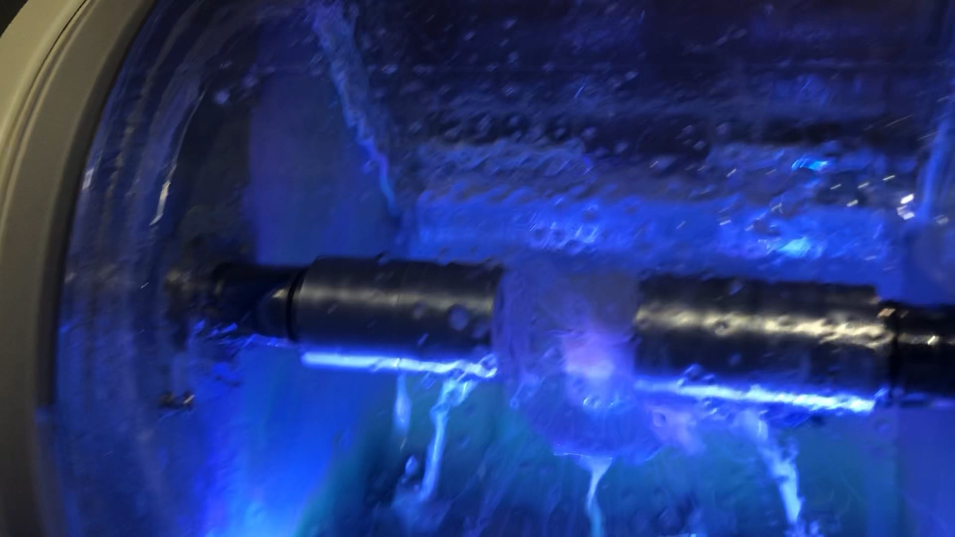
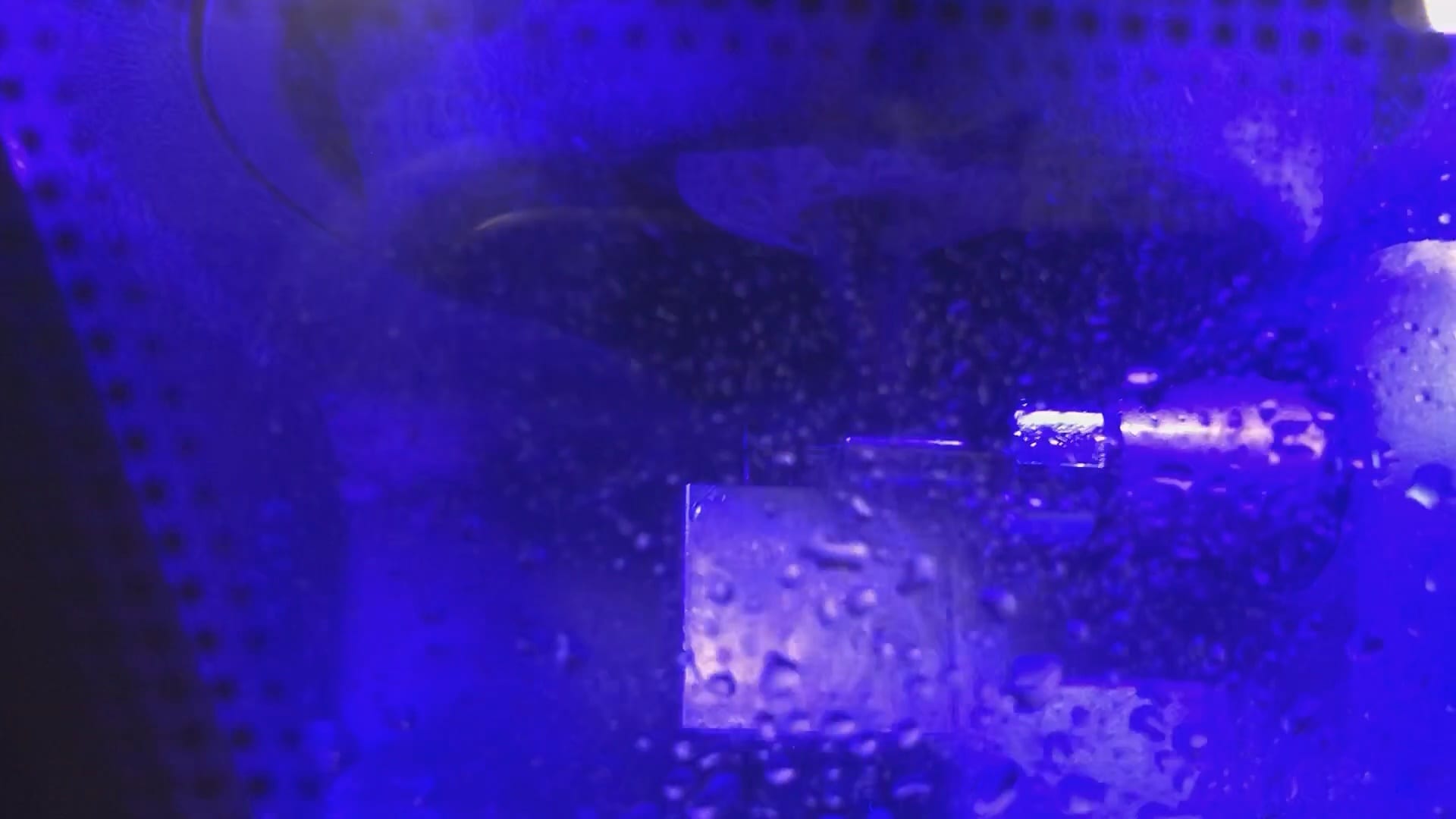
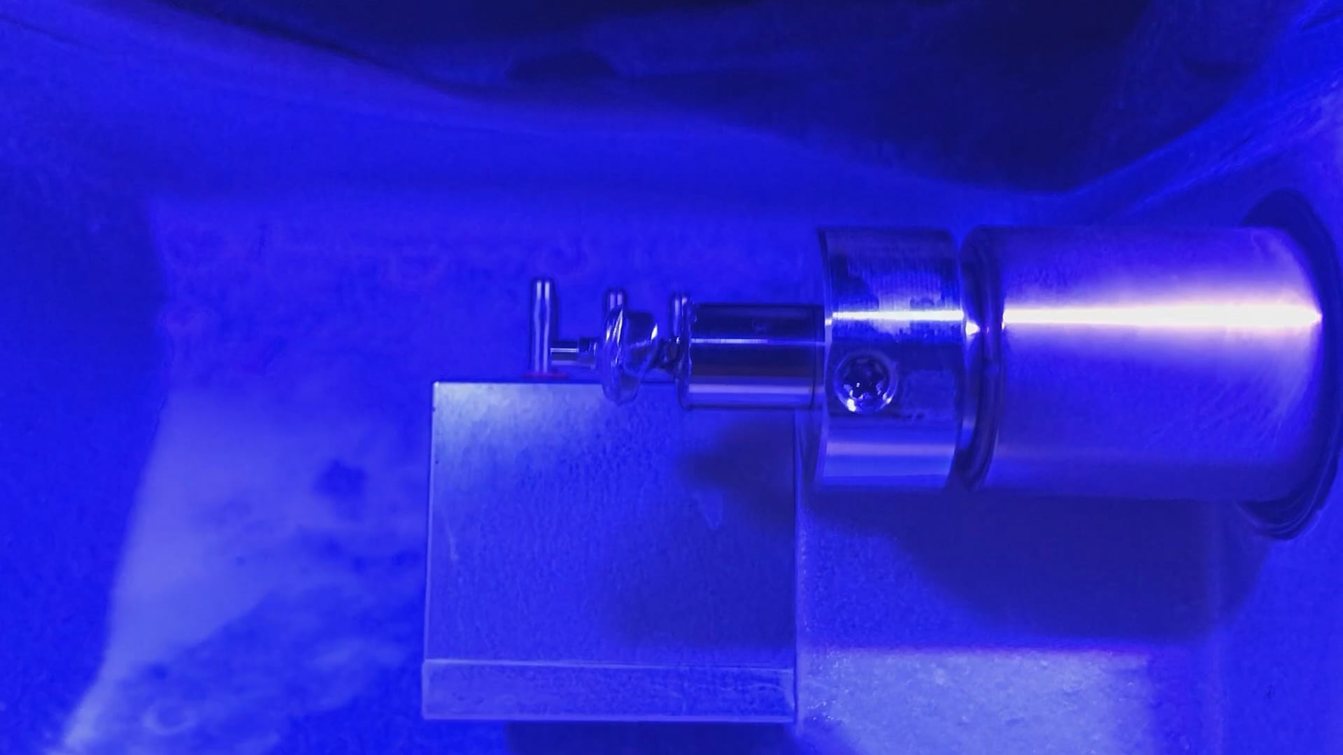
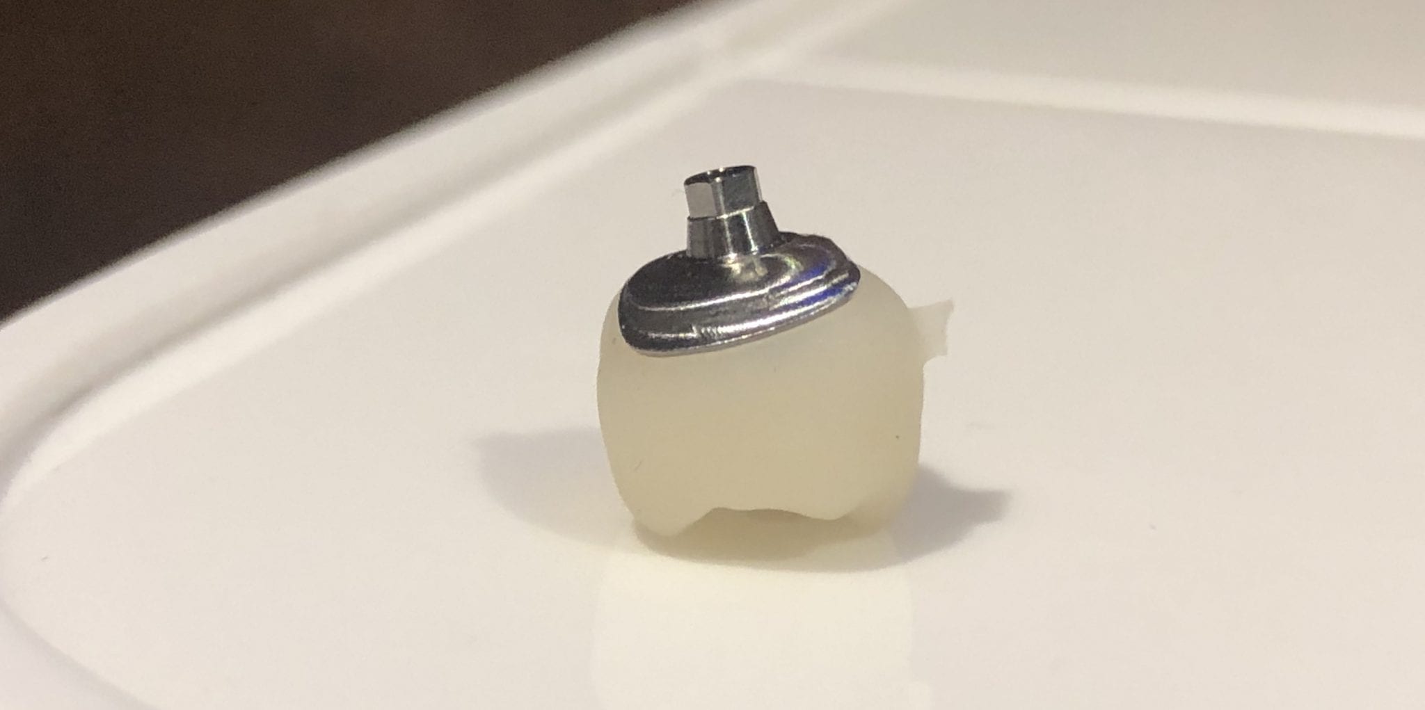
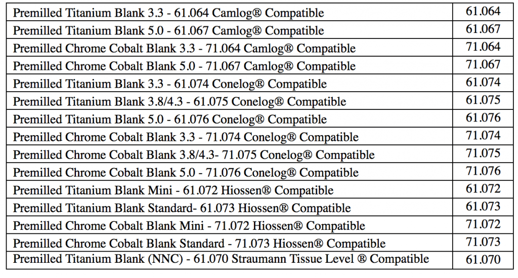
A custom titanium metal abutment is milled in such a manner where the drills DO NOT touch the connection. The type of connection is predetermined by the blank manufacturer and the cylindrical part of the abutment is milled out. This makes the symmetric geometry of the abutment a bit tricky for some to handle as indexing it properly to manage the timing of the connection is critical for easy delivery.
It is a good idea to know the exact dimension of the screw access hole. You want to set the diameter just outside the channel so that you don’t have to do a lot of post production adjustments. if it is made too thin however, you can have a mis-mill and have to repeat it. We’ve found 2.5 mm the perfect setting for the DESS titanium abutments.
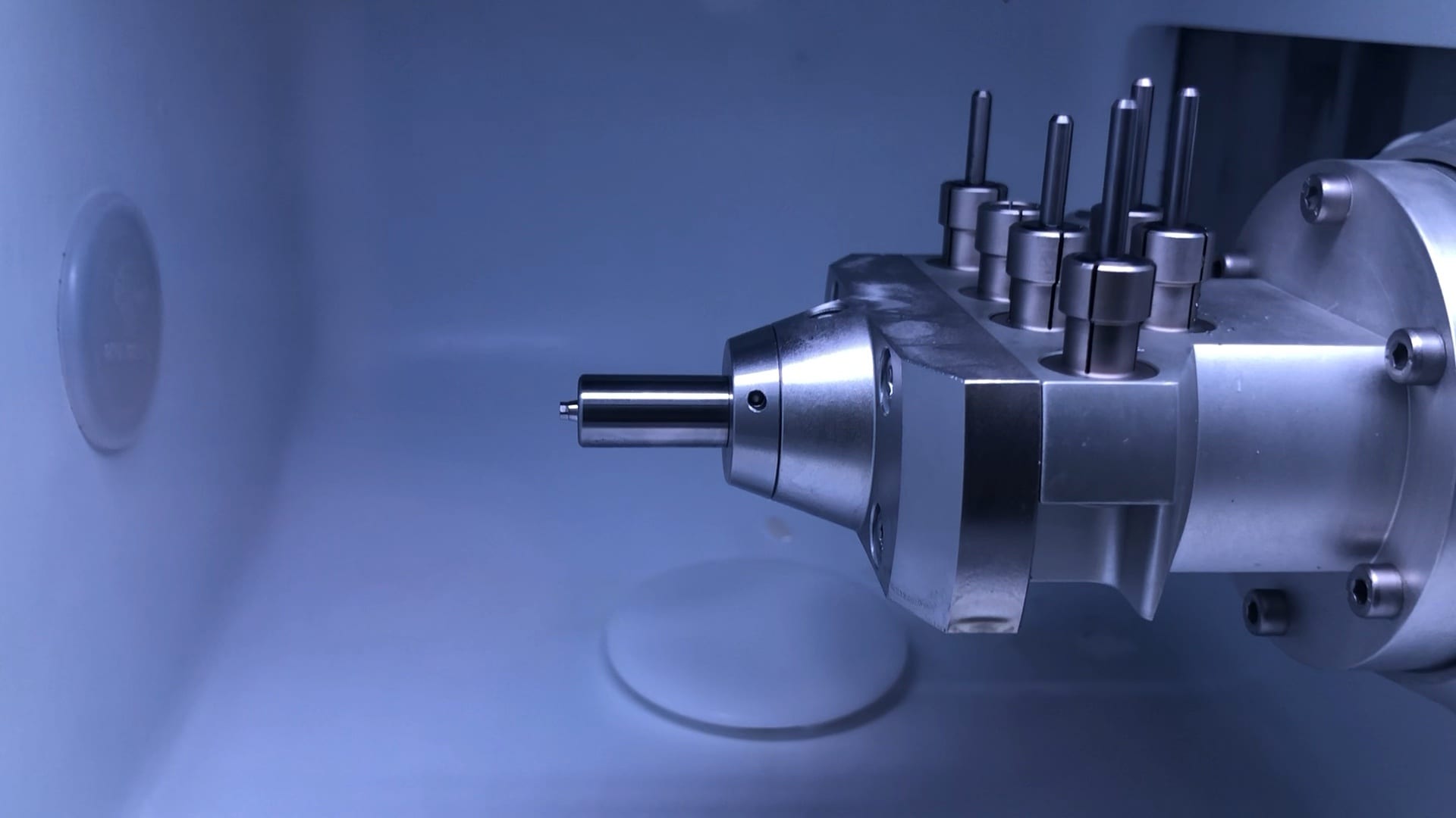
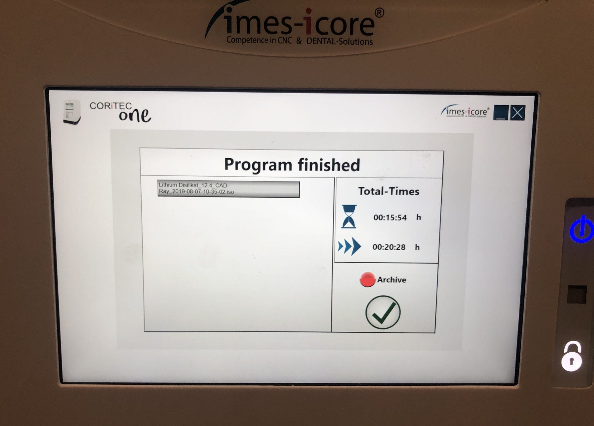
With the Meditlink software you can design a case and then export the designs and take them to any milling machine of your choice. In this demonstration, we use the CORiTEC ONE to mill out the metal abutment in 45 minutes. This procedure is not intended to be a single appointment visit so timing is not critical and you don’t place undue wear and tear on the milling machine.
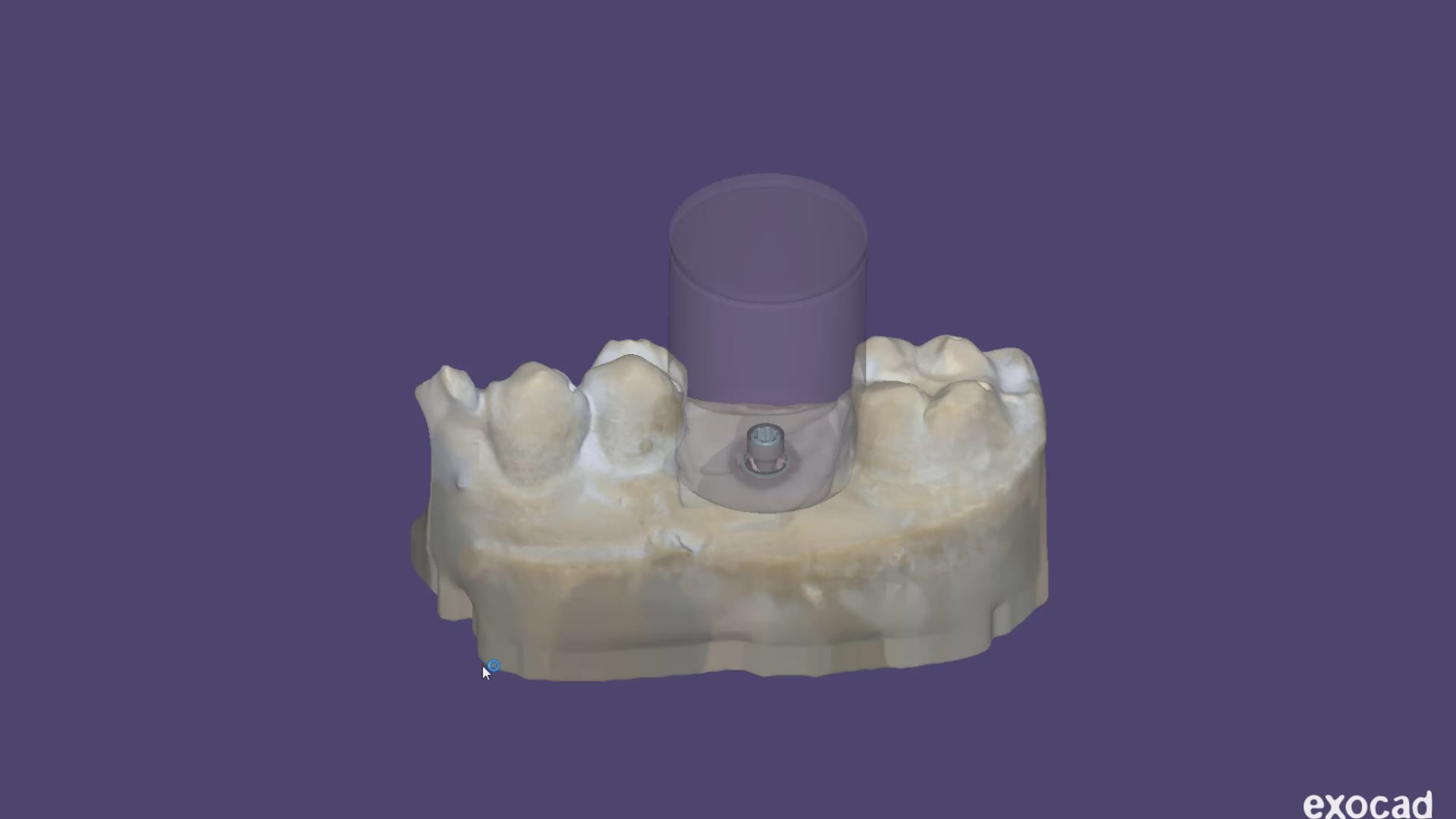
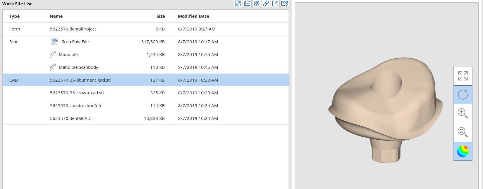
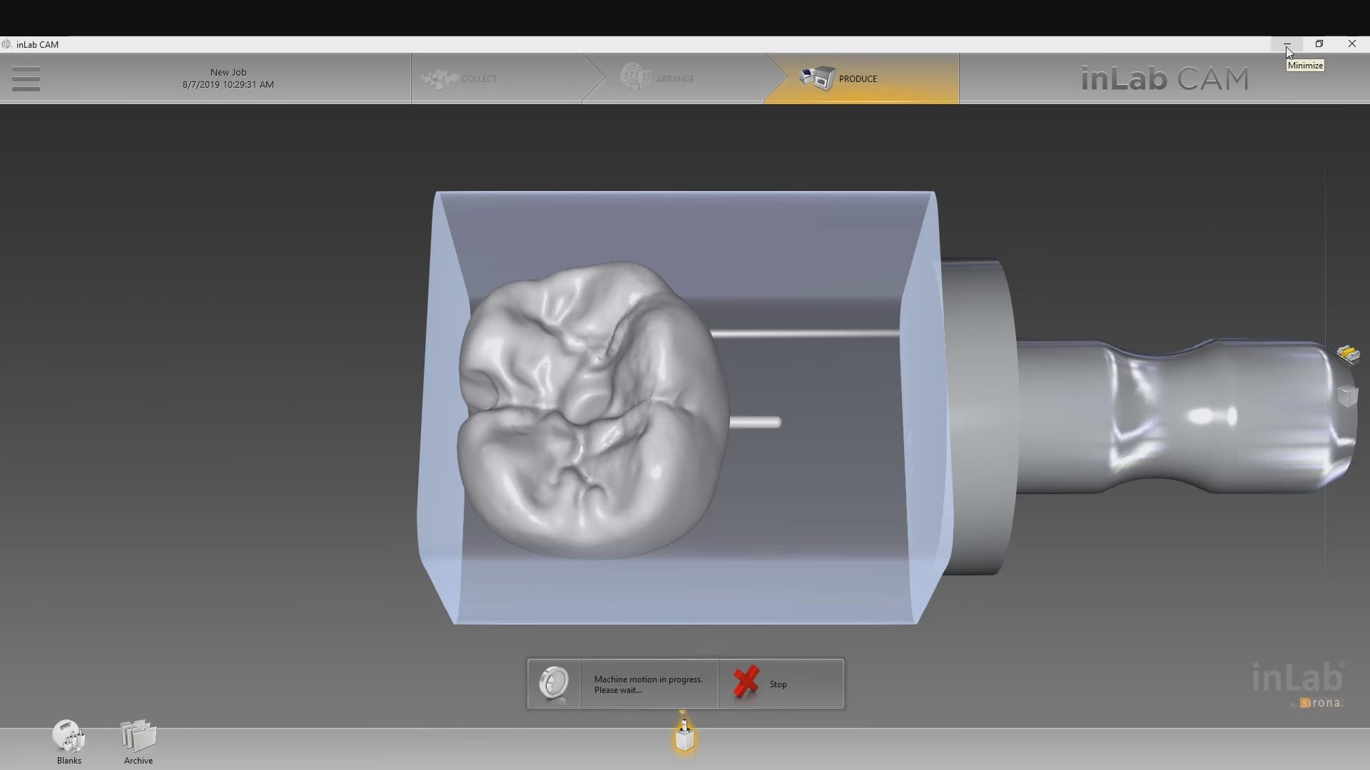
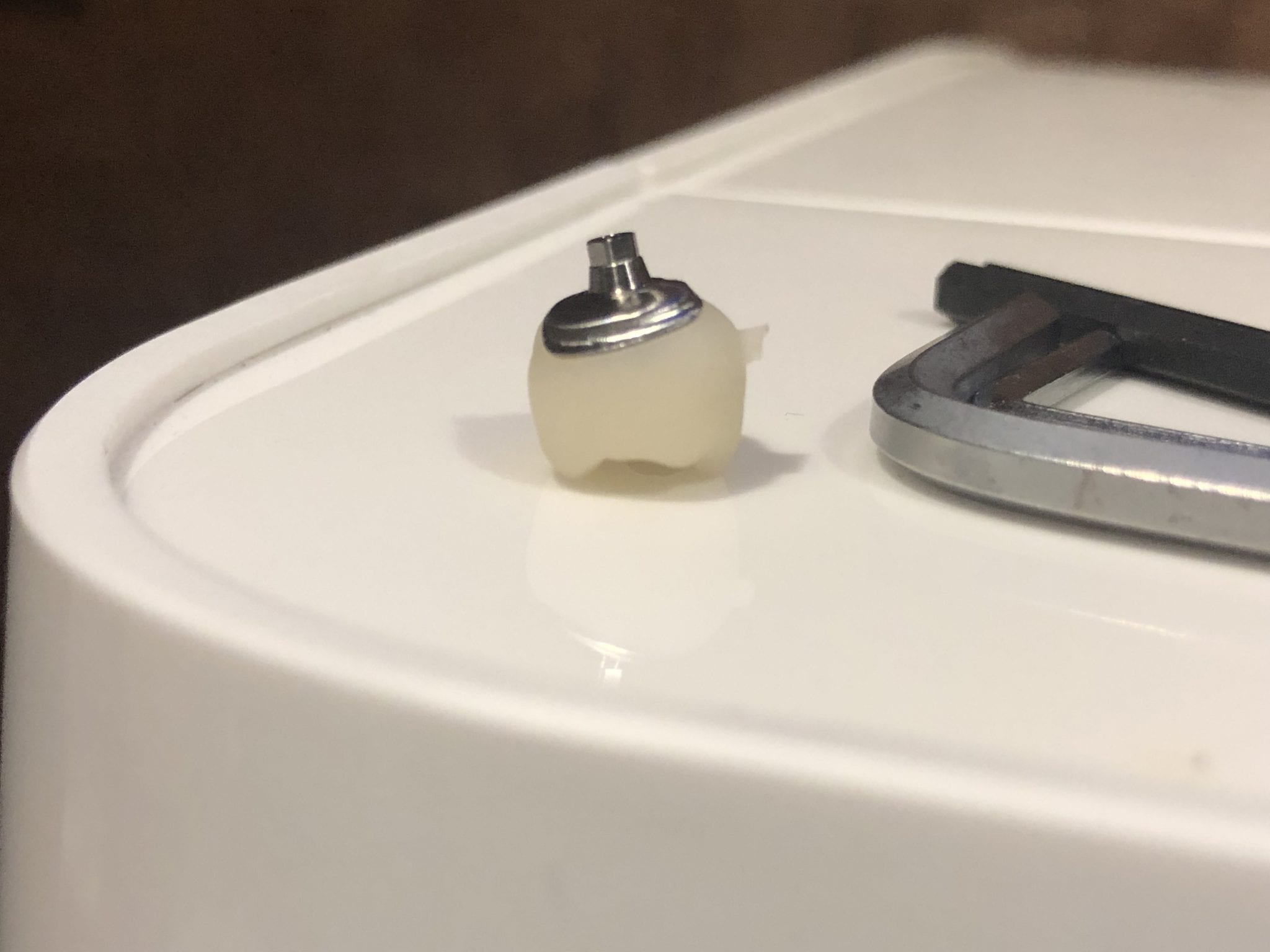
The crowns were milled with two different milling machines. A Celtra Duo block was used and milled with the CEREC MCXL and retrofitted to the abutment to verify the fit and accuracy. The same crown stl was milled out of Vita material in the imes icore machine. The whole point of the demonstration is that you can take scans from any intra-oral scan, take it to CAD software (in this case exocad) and then export the case and take it to any printer or milling machine of your choice. You must make sure critical information is accurately transferred from your CAD software to your CAM software, which is generally the construction / project file that accompanies the STL files of the prosthetic components
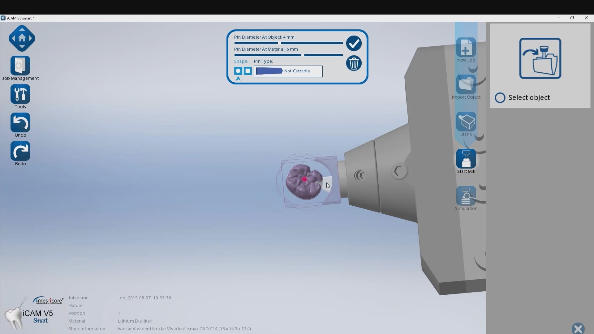
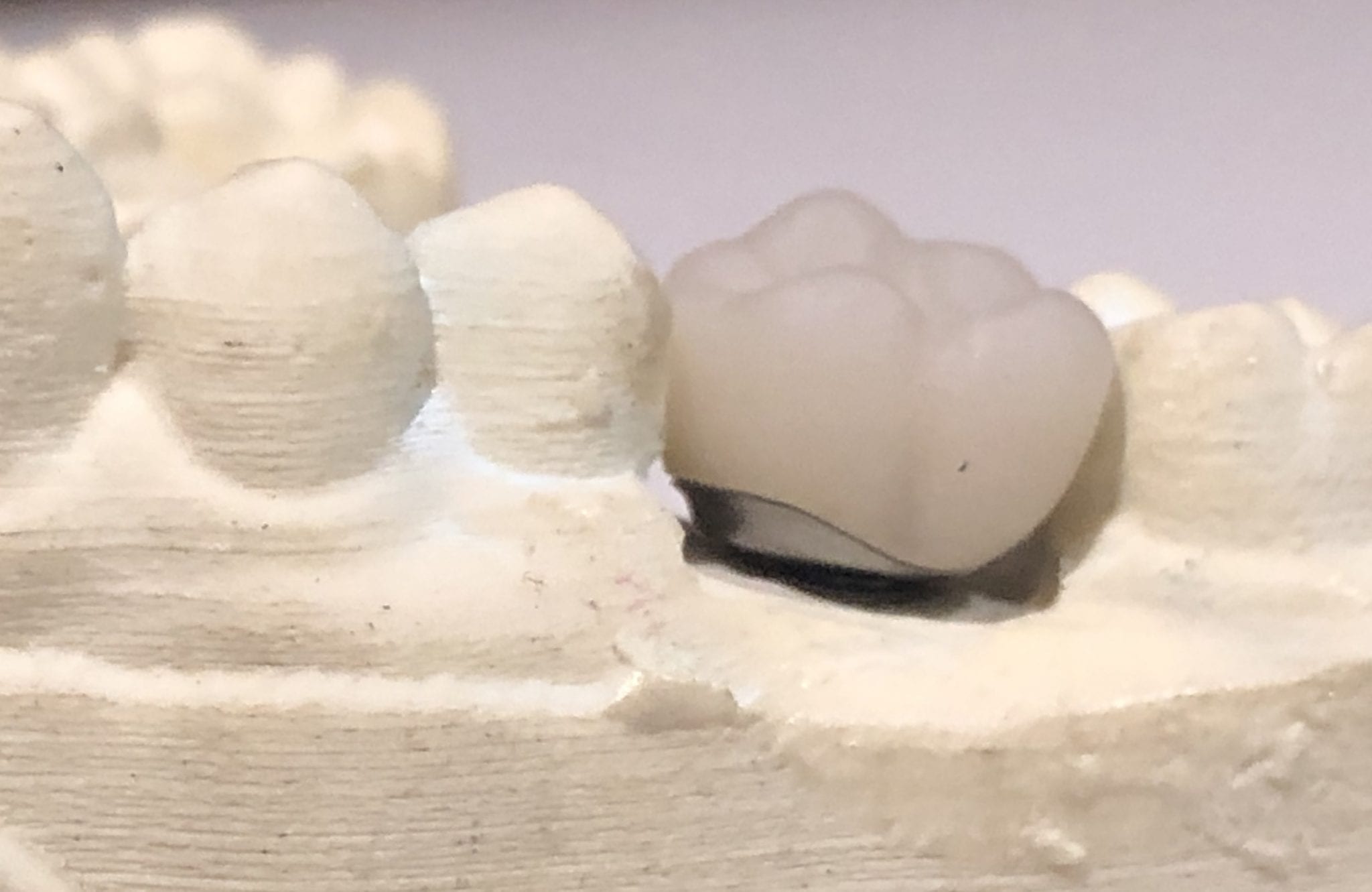
The same crown was milled out of Vita’s Suprinity material in 20 minutes with the imes-icore CORiTEC ONE. Take note of the internal adaptation of the metal abutment and the restoration and how when it is flipped upside down, the restoration does not fall out easily!
When we 3D scan the surface of an object, we plot geometric figures (usually triangles) on the surface of that object which is usually round or has some other geometric shape. A satellite beam hitting the surface of the earth is a good way to visualize the scanning process as the photo illustrates.
As you span across long distances, a meshwork of triangles are plotted together to accurately represent the topography of the object. You can start “veering off track” and forming models that are inaccurate representations of that object if you don’t properly form this framework. There are many variables that can introduce these errors including simple matters like speed of scanning.
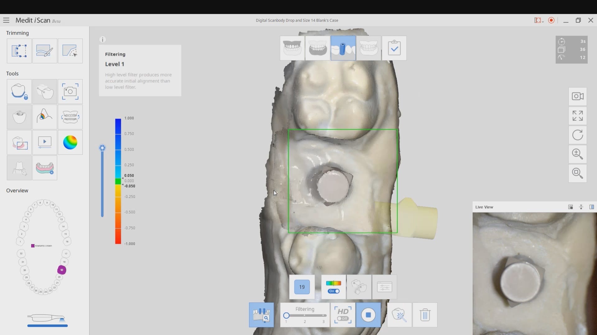
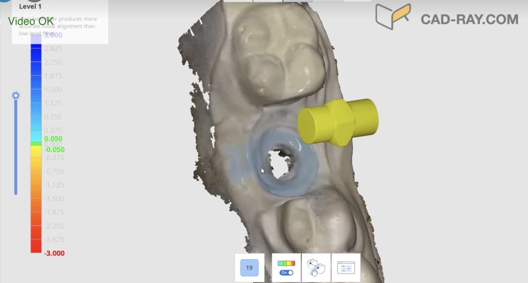
Now, with this dental artificial intelligence program, the software can digitally plot and drop known shapes on top of attachments or devices we place in the mouth. Color mapping can let us know if we are staying accurate, on path, or introducing errors and deviations!
Now imagine if you have 6 objects sticking out of a flat plane that this AI program readily recognizes. Identifying these landmarks is the first step, but the bigger significance is that we can scan from object 1 > 2 > 3 > 4 > 6, and when we continuously to image backwards from object 6 to object 1, and our color coding remains the same, we are guaranteed scan accuracy.
People go to 2 extra years of schooling to do accurate work in complex cases, most of which will be replaced with software algorithms like this. This is a serious and significant advancement in dentistry, particularly in implant dentistry. Here’s a video that detail how we use it to restore dental implants.
In the following three videos we walk you through the steps of how the digital “scanbody drop” works to identify the location of an implant fixture. In the demonstration videos, we highlight this upcoming feature and how you an integrate the CAD software for implant designs and restorations. In the final video, we demonstrate how you can take the construction files to the milling machine of your choice and mill out the abutment and/or suprastructure.
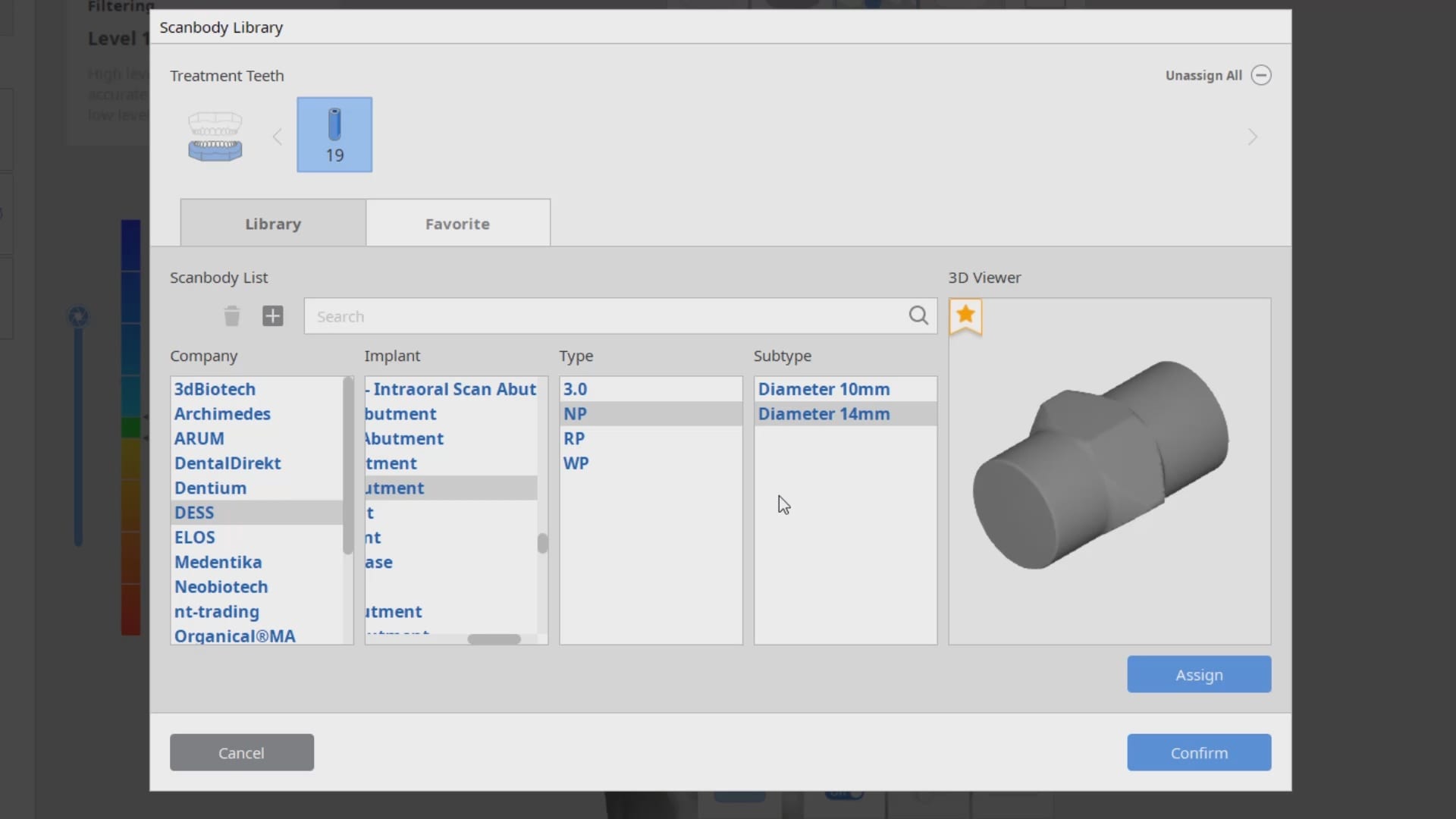
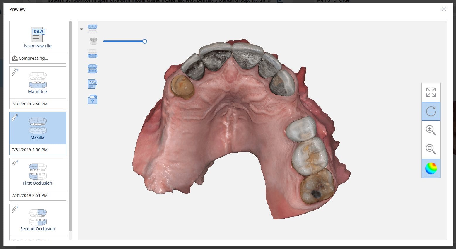
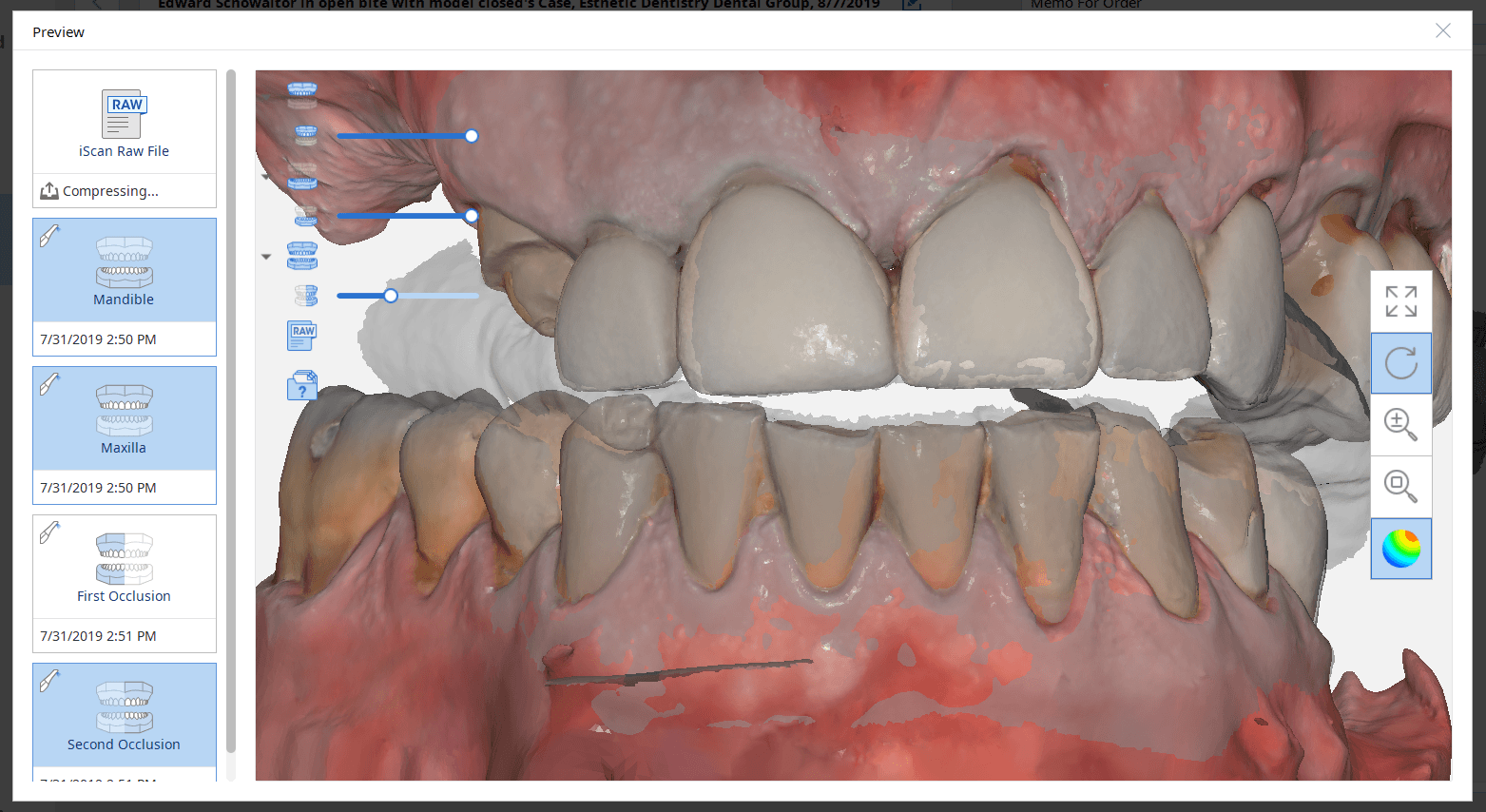
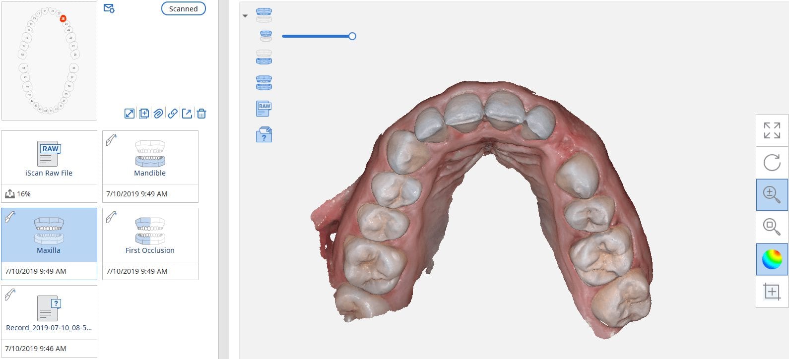
The Medit i500 intra-oral scanner has two different software programs to operate, one is of which is geared towards clinical dentistry and the other is geared towards laboratories. Our advanced users are encouraged to use the lab version as it has a lot more functionality. One of them is to directly link to exocad software.
In this particular preview we show you the interface where you can launch the iScan program and define the work order and set all the parameters for your restorations.
Once all the settings are chosen, you launch the Medit scanner and image the case. Here, we defined the custom abutment for the crown and the opposing, which activated the catalog box for the antagonist, the arch, the scanbody, and the buccal bite. All respective images were captured.
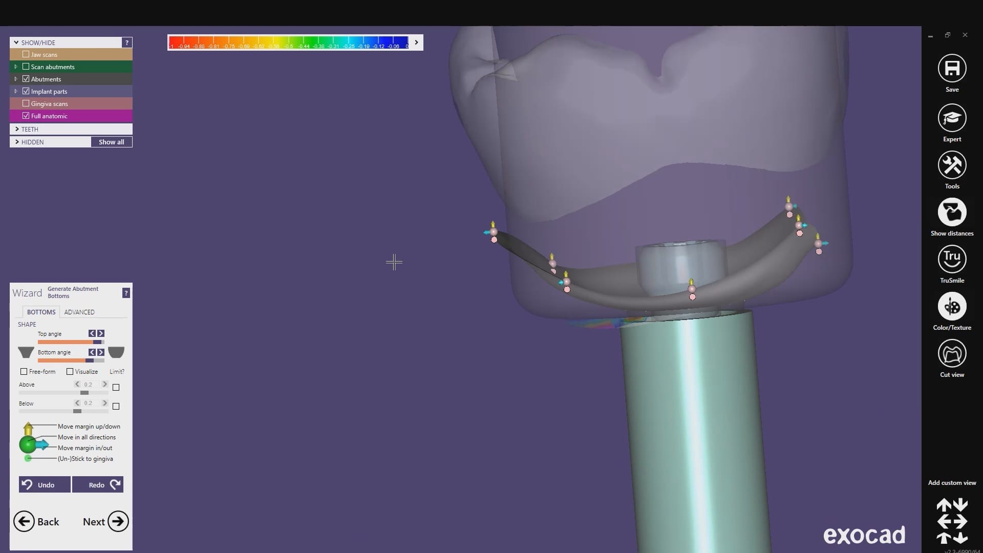
Once the implant type is identified then you can design the abutment and crown with great control, where you can contour the underbelly of the abutment to help provide tissue support.
The design and the construction file is taken to the milling machine. Here, we used the CORiTEC ONE to mill the titanium abutment and then the Lithium Disilicate crown. You can see the great internal adaptation when the crown and the abutment are flipped around completely and the abutment does not fall out.
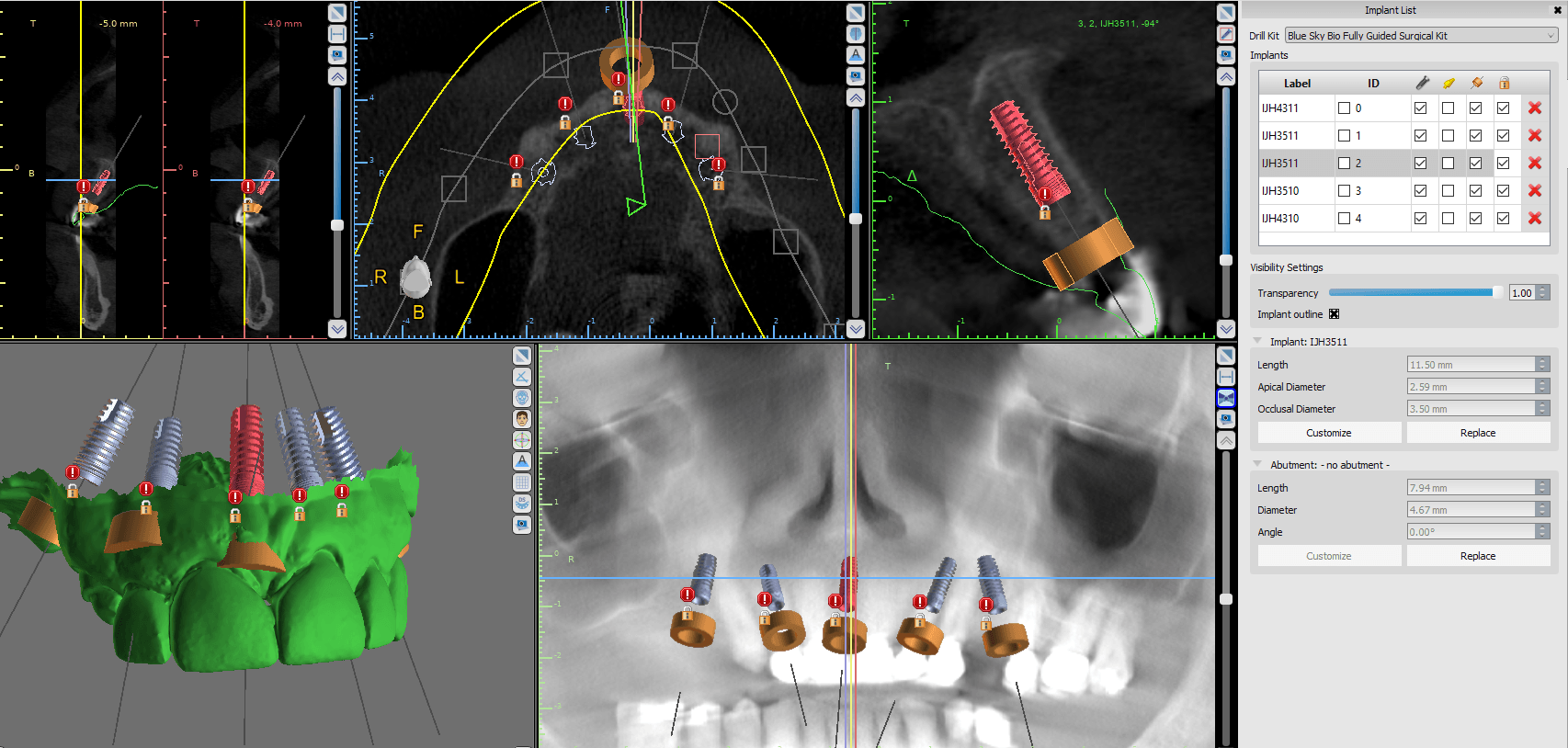
In this case presentation, we scan a patient with the medit i500 for implant planning and restorations in the upper left quadrant. At first, you will notice how the camera was slow to capture the arch due to water spots on the mirror of the camera tip. Once these water spots were removed, the imaging was rapid and the whole upper arch was imaged in just a minute.
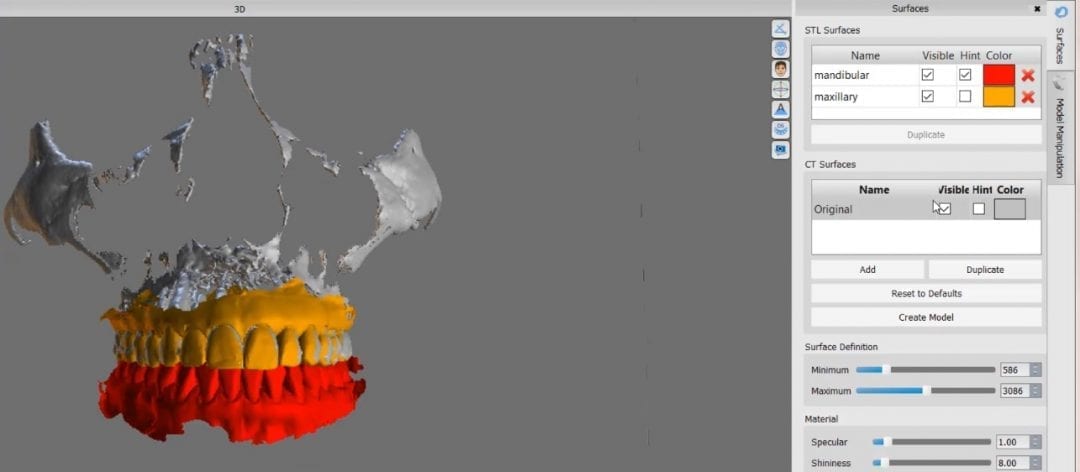
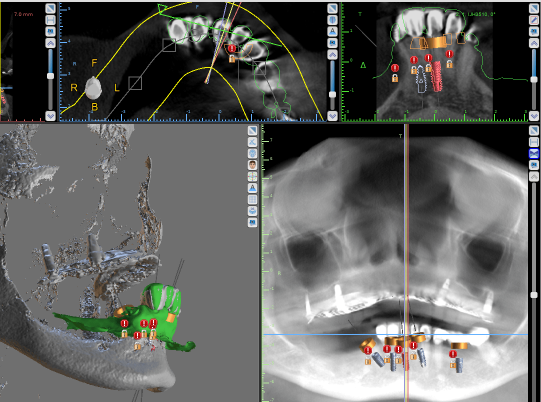
Once the upper arch was digitize it was automatically merged with the dicom data from a ct scan in the blueskybio software. This automated step saves quite a lot of time and is rapidly becoming a reliable solution. It is imperative that you do NOT form a base or close holes in your intra-oral scans so that the software has an easier time to stitch the models together.
The implant case was designed and a surgical stent was fabricated for fully guided surgery. The lip line and the tooth position will be a challenge and the angulation will have to be corrected with an angled abutment
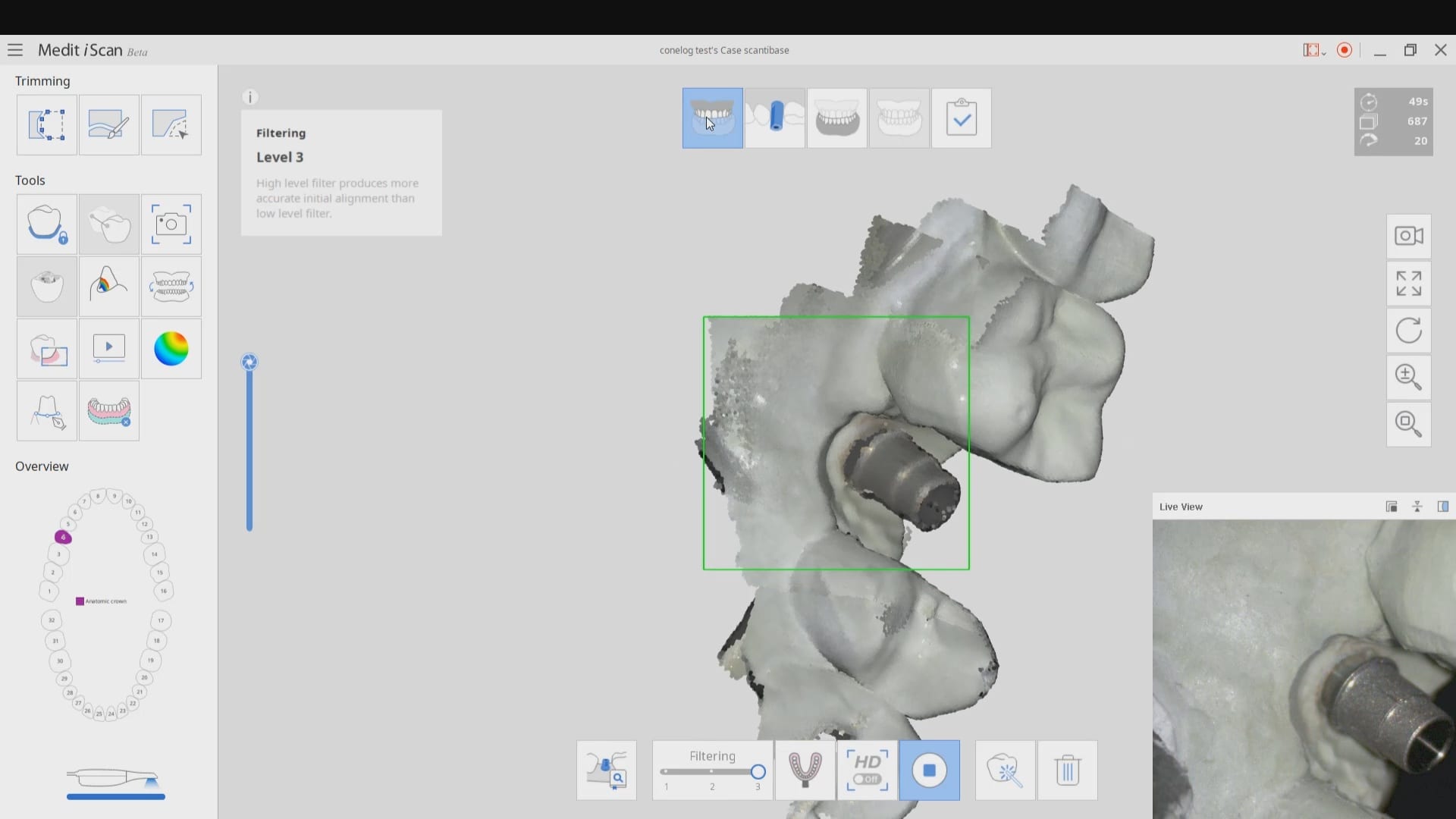
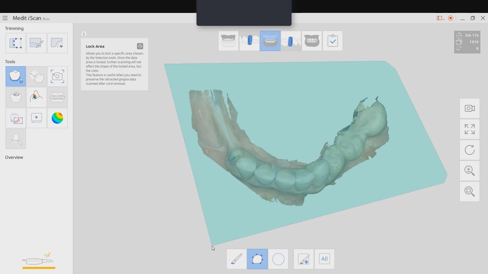
The Medit i500 software can now identify a scanbody and digitally place a virtual one in its location. This has a lot of ramifications. For starters, this great opportunity affords a dentist the ability to image multiple implants in long span edentulous areas, where you would have a clear indication of distortion or artifact introduced during challenging scans.
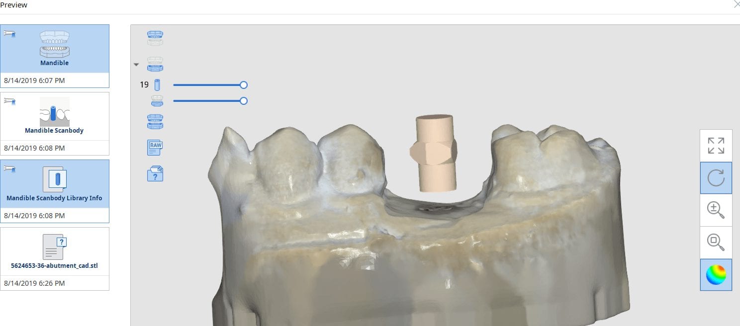
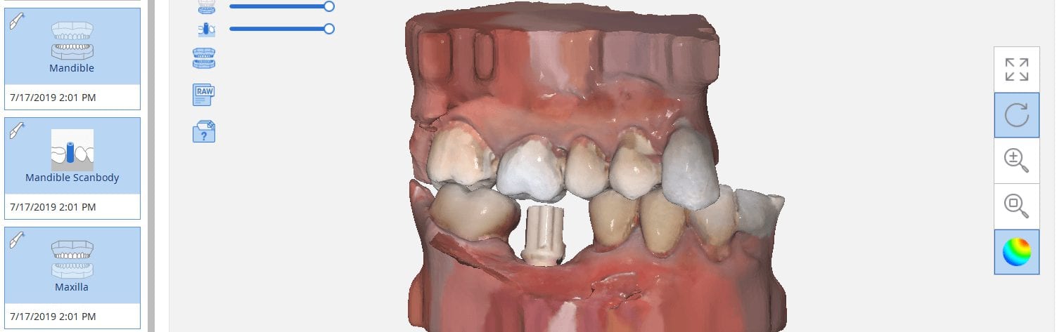
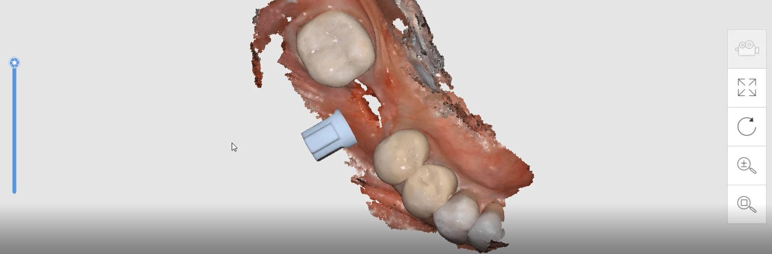
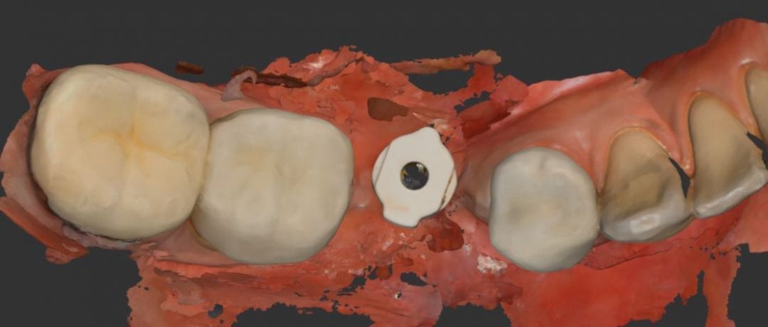
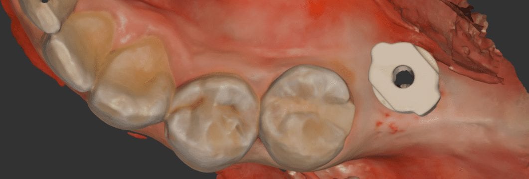
In this single unit case in the video below, we preview this feature. Once the patient is anesthetized, the isolite was placed to protect the airway and the edentulous area was scanned.
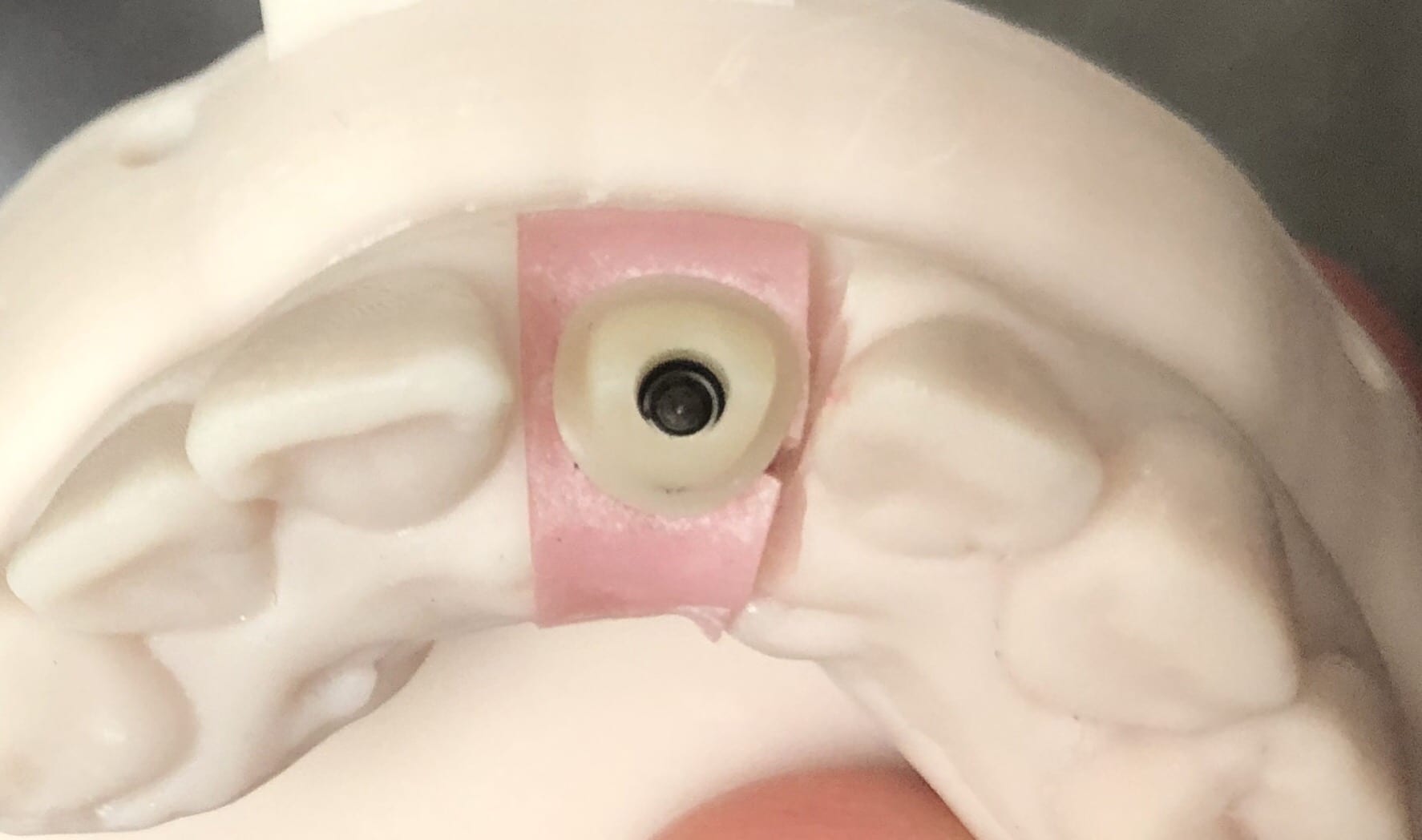
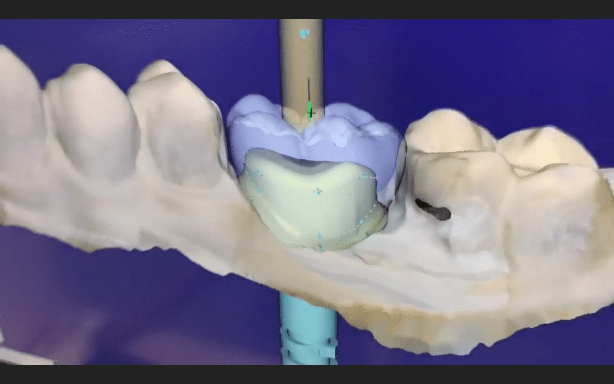
After uncovery of the fixture, the type of scanbody was identified in the menu and the location of the scanbody was identified on the digital model.
Once scanning was resumed, the digital scanbody was placed on top of the intra-oral one. As more data was captured you can appreciate how steadily the software tries to adapt the physical fixture to the digital one.
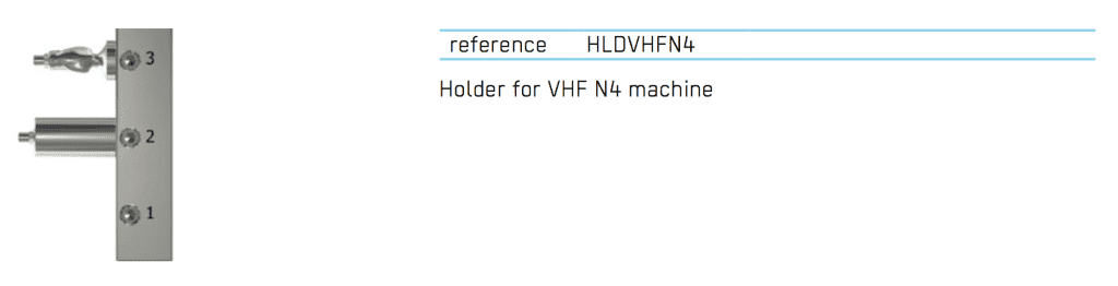
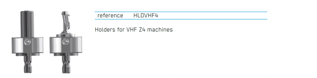
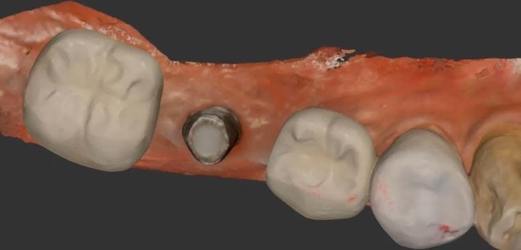
The Z4 Milling Machine can drill emax, zirconia and metal abutments. You can use a scanbody, identify the location of the fixture, design the abutment and mill our either ceramic or metal as the abutment.
Metal abutments in the posterior molar areas, tibases in canine and premolar regions, and angled abutments in incisor area is the general consensus for restoration of choice
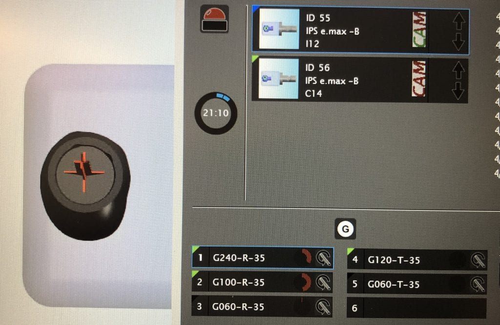
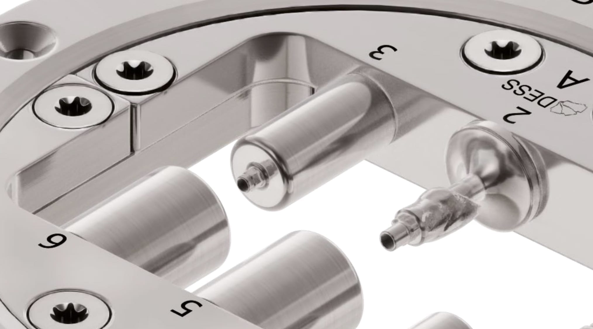
One of the greatest advantages of the Z4 is that it can start milling while it is doing the calculation for milling. Furthermore, you can load multiple designs in preparation of continuous milling. In the picture attached, the CAM software is shown which operates in the background. Most users don’t usually see this interface.
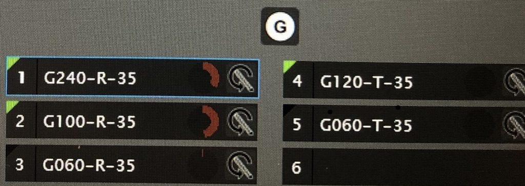
Here you can see how there are 5 drills for the machine. The top tier, consisting of 3 drills, labeled G240, G100, and G060 are all labeled as R. The G120-T and G060-T are used only for a screw access holes
When planning for guided surgery in edentulous patients, it is important to have the final vertical dimension and tooth position determined. Ideally, a denture duplicate should be used with proper radiographic markers.
The traditional way was to embed radio-opaque material in the denture dupe, CT scan the patient with the denture dupes, and then CT scan the denture dupes themselves. Alternatively, you can scan the denture duplicates with a digital impression system. Here we used flowable composite and spread them through the wax set up and take a 3D X-ray of the patient. We then use those landmarks to merge the data sets between the digitize denture and the markers on the CT Scan
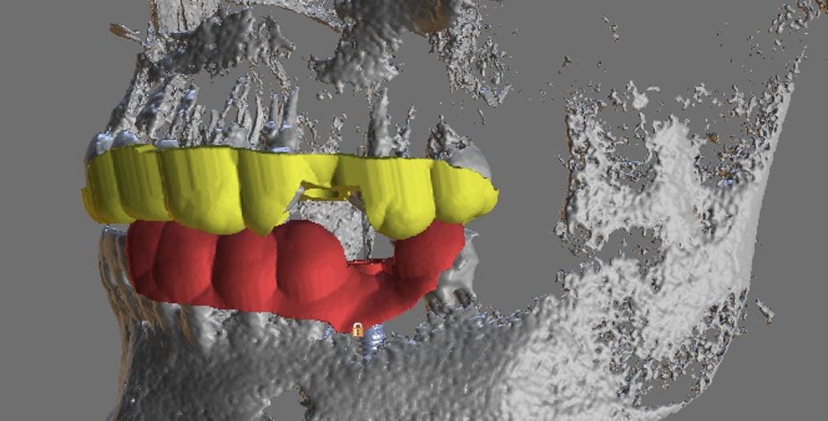
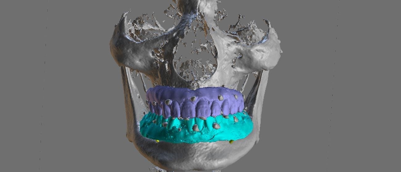
Once the dentures are digitized and merged with the CT data, the cases is analyzed to make sure there are no gaps in between the intaglio of the denture and the soft tissue of the palate and the lower / mandibular ridge
An important concept to keep in mind for these edentulous cases is that you actually need 2 models for each arch. One model is used for tooth positioning and implant design, and the other model is used for stent design. Essentially, you design the stent on the ridge, not the denture dupe
One of the biggest hassles in most software is to plan a guided surgery case when the tooth is still present in the arch. Some software will force you to part-take in pylon course handling, gymnastics maneuvers, musical chairs, and multiple imports and exports. The issue revolves around the placement of the sleeve / ring in the design step. Usually you are forced to manipulate the data in 3rd party software and then bring it back with the tooth virtually extracted.
This article is about how you can scan the arches and export the STL, OBJ, or PLY data from the Medit i500 scanner. You can then clone the same case and alter it- namely, you can crop out the tooth that will be extracted in the future. This video shows you how the virtual extraction is performed.
The multiple data sets are then imported in BlueSkyBio software where there are no limits to the number of models you can bring in. In the following video, you can see how the complete upper arch, the virtually extracted lateral arch model, and the opposing are brought in an merged with the CT Data.
The implant is planned for fully guided procedure and a surgical stent is manufactured on the model that has the virtual extraction. You cannot design a stent correctly with the tooth present in the equation. Open architecture and speedy results are the name of the game now with CAD/CAM dentistry. As you can see, these steps are super fast and easy with the open licensed Medit Scanner
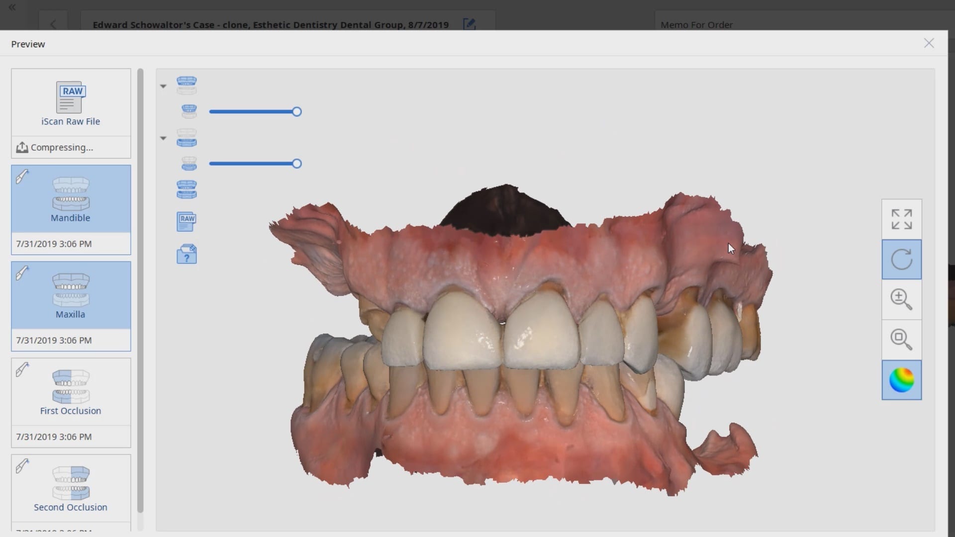
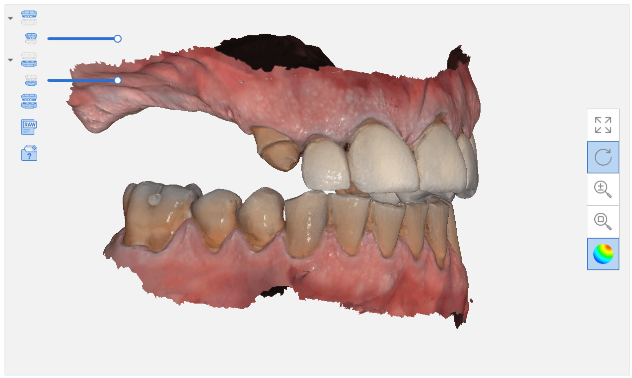
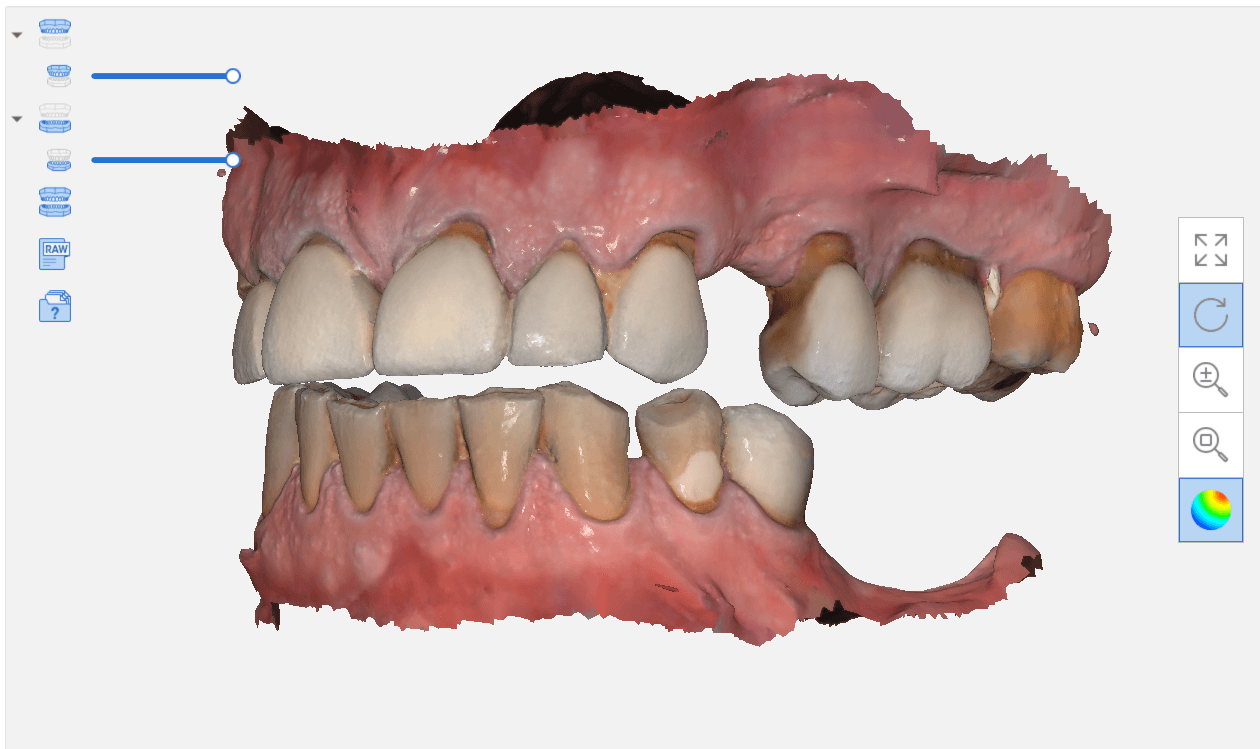
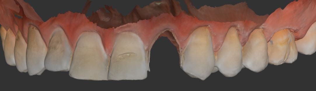
Another example of how well the i500 from Medit can scan with a deep focal length. This is impossible to do with any other IOS system on the market. Don’t misunderstand, this is not an easy impression to capture, but if you are well trained and know what you are doing, it’s very accurate and simple.
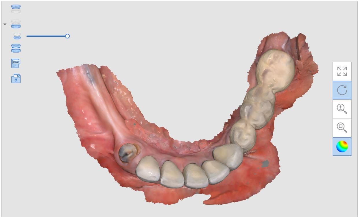
In this video you will see how the upper arch is captured in under a minute. Then the lower arch is capture with the healing abutment removed. Watch carefully how there is a lot of effort made to capture the distal wall / contact area of the bicuspid. You can also see the effort made to capture information below the height of contour of the distal molar. The mesial information is critical for designing the emergence profile of the abutment and restoration
[videopress 2Di5fUxy permalink=”false” hd=”true”]
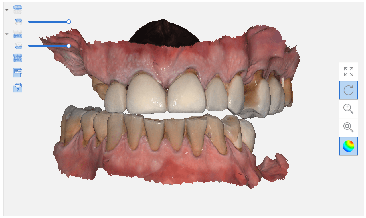
After both arches are captured, the software leads you to the step where you capture the peek impression post. It is seated completely and an X-ray was taken to verify the accuracy. The edentulous area where the abutment would be positioned is cropped on the Meditlink software, and the impression post is scanned. It is imperative to make sure the adjacent teeth are imaged so the software can properly line up the landmark of this scan with the previous scan of the edentulous mandible.
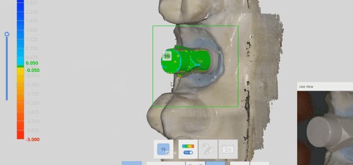
After the Peek Scan Body for a Narrow Platform is imaged, it is removed, and the patient bites down into maximum intercuspation. The camera then captures the data so that it can articulated the models together. The buccal bite scan turns green once a positive adaptation is made.
[videopress LF2bvJPR permalink=”false” hd=”true”]
Once the relationship of the upper arch and the lower arch are confirmed, the case can be submitted to a lab for the manufacturing of a custom abutment. You also have the choice of fabricating chairside abutments with a milling machine, if you choose to.
When you scan an upper arch and a lower arch with an intra-oral scanner and then export that case, usually the software places coordinates on the upper and lower models, so when you import them into another software, they properly articulate.
In this video, you can see how the upper arch is stitched to the CT image of the maxilla, an then how one can easily related the mandible stl file to articulate to the upper arch. This comes in handy in software like BlueSkyBio where you could add teeth to the equation and design implants so that they are prosthetically driven during the design phase.
In this video, you can see how a quadrant of the lower arch and the upper arch can be imported into a third party software for design. Note that in this particular demonstration, there is not edentulous area and this video just demonstrates how you can place a digital tooth in your case and design the digital wax up to your liking. Advanced users generally just use the sleeve of the surgical stent to aid them in visualizing the occlusal table of the final prosthesis. A complete design lets you know where the contacts are and how much space you need to create the proper emergence profile.


 When we 3D scan the surface of an object, we plot geometric figures (usually triangles) on the surface of that object which is usually round or has some other geometric shape. A satellite beam hitting the surface of the earth is a good way to visualize the scanning process as the photo illustrates.
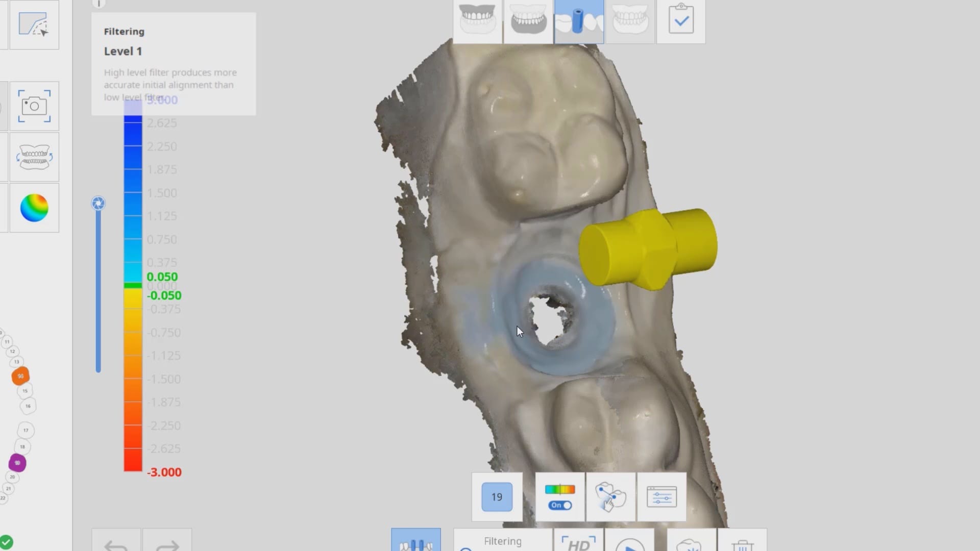


 [videopress SYc88hMJ]