


Implant Planning of Upper Second Premolar and Lower First Molar

In our 2 day hands-on course, we make sure our doctors get comfortable with full arch scans in speedy and accurate fashion. One of the greatest feature of the Medit iScan software is the reliability map. Watch how we image this full arch; every camera position and movement serves a specific purpose, which is to plot as much data on the X, Y, and Z plane so that the camera and software can always recognize where it is in reference to previous data captured.
Note how we move the camera back to a position in the arch to reinforce the fact that it is “on track”. The more data it recognizes the more accurate it can be in full arch imaging. This is true for all intra-oral scanners and the same principle can be applied to all of them. This should also explain to you why imaging an edentulous area is harder to do with all scanners- there is less data (or no data) on a vertical plane for it to recognize and to use a reference frame.

This is an advanced case and won’t make any sense unless you have taken our course on digital dentistry. If you are an advanced user, watch how we break this complex case up into many small manageable segments to create full arch impressions of multiple prepared teeth.

Take note of the fact how the buccal bite is captured over a long course of time. This indicates that the arches are related to each other properly and we have not lost track of the bite. Pay attention to how we operate “independent of time and sequence.”
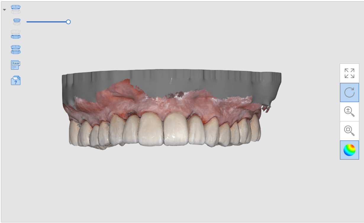
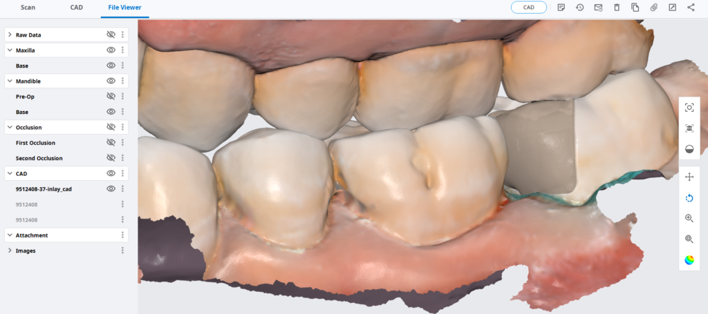
Immediate Post Op
Post op intra-oral scan with Medit i500 to capture irritated and hemorrhaging tissue (for demonstration purposes only)
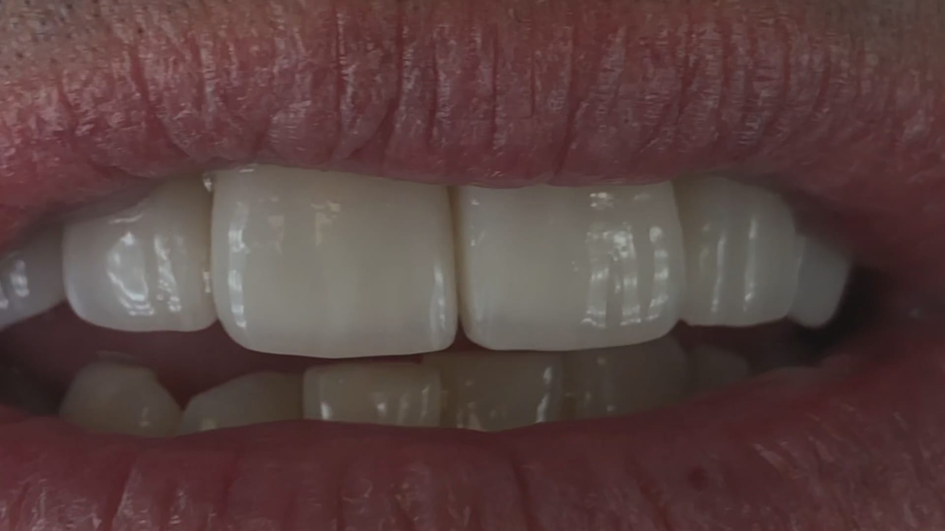
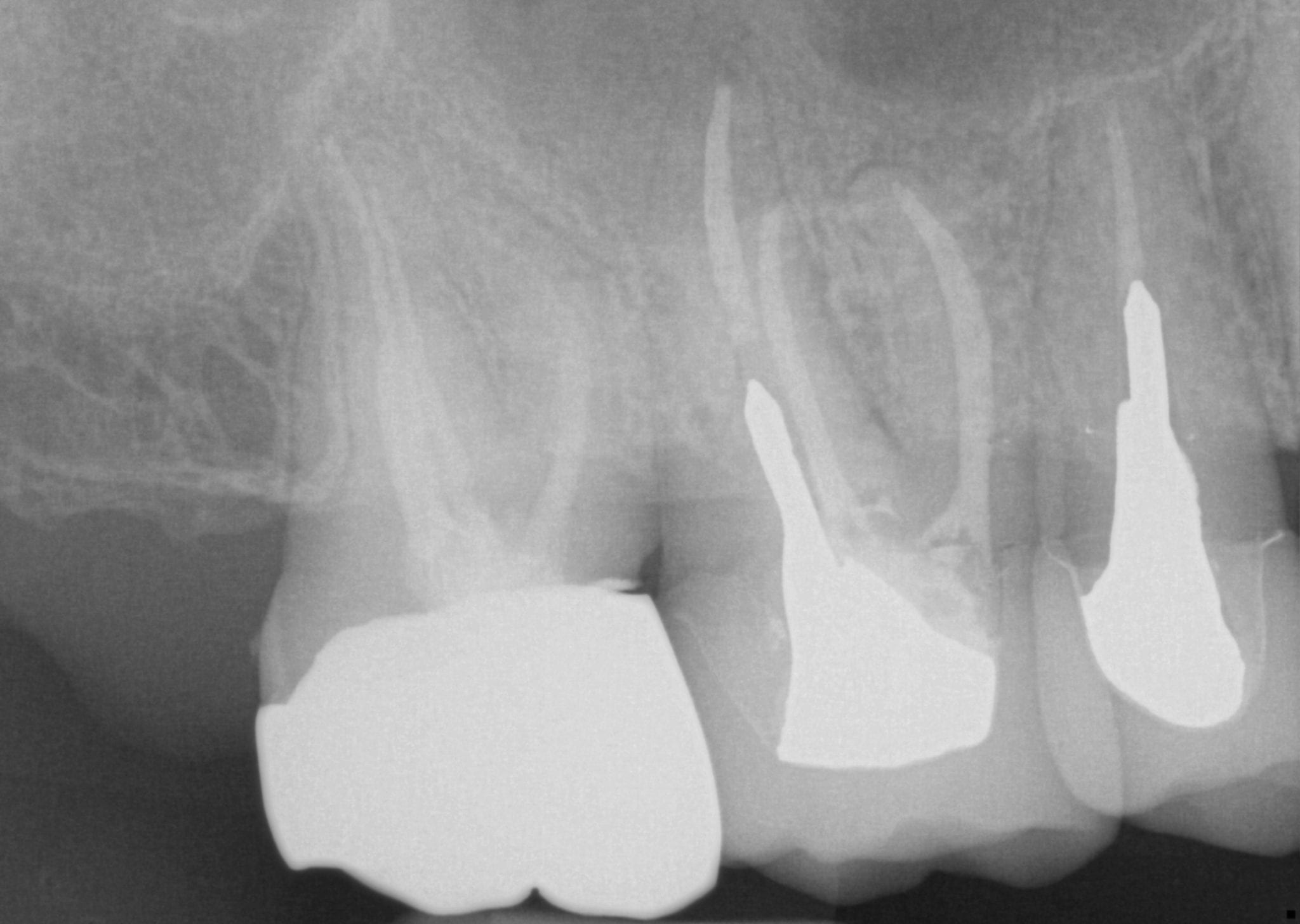
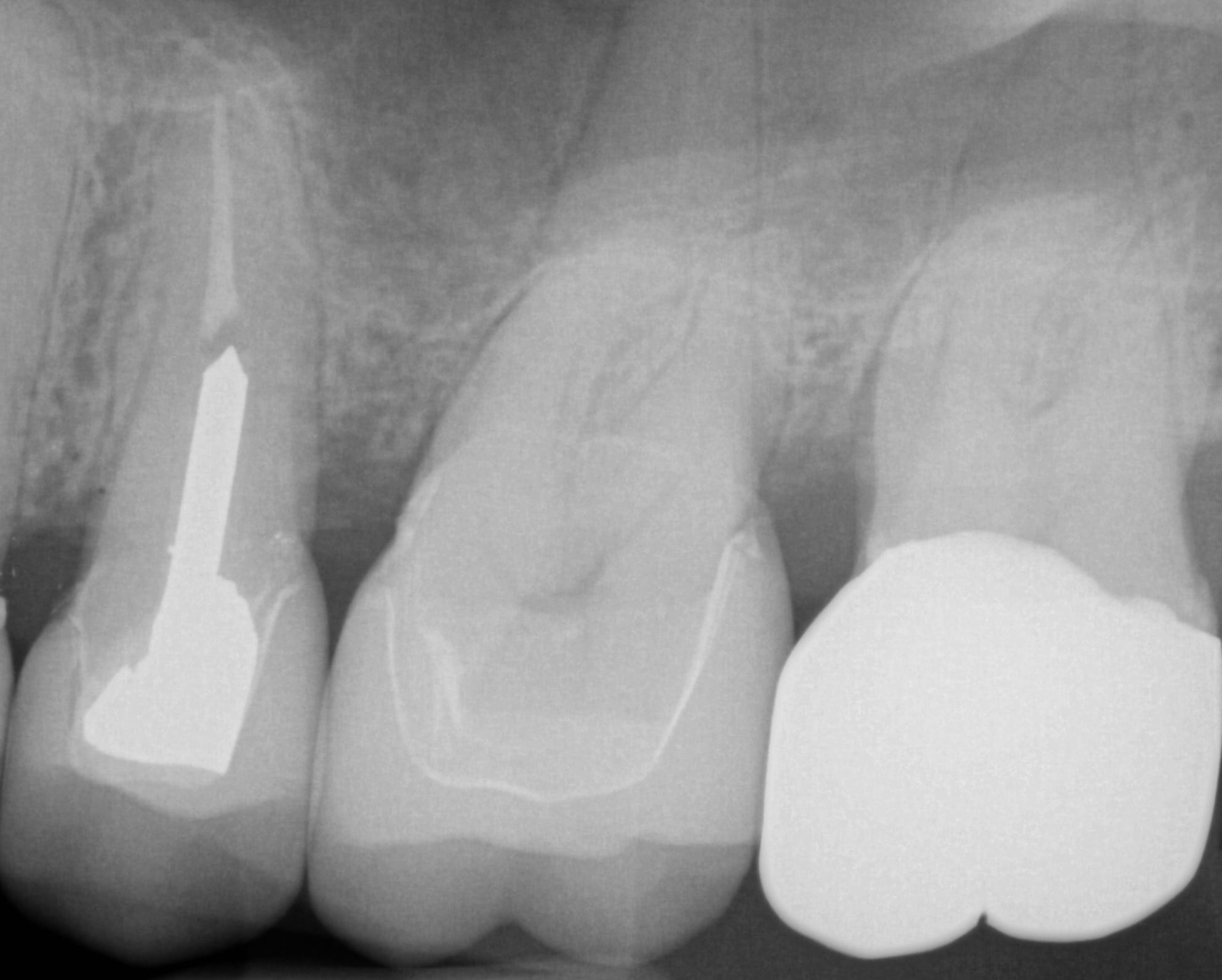
One Month Post Op with Radiographs

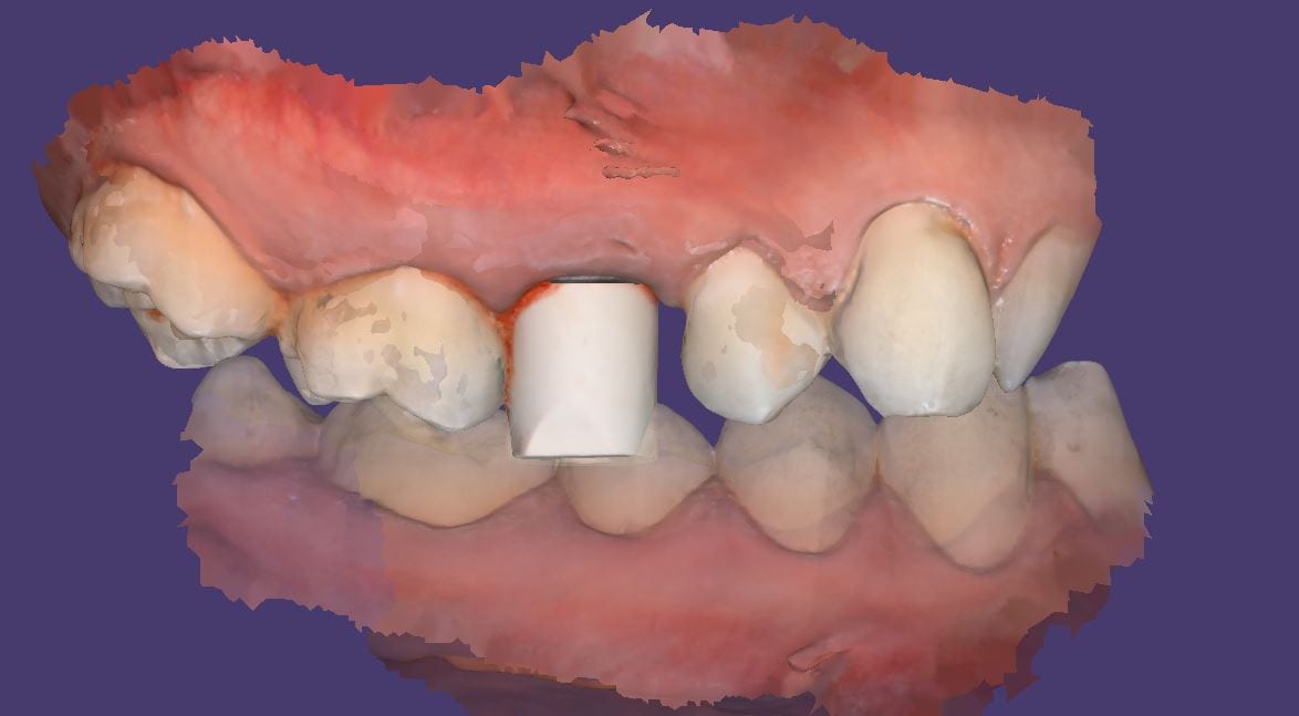
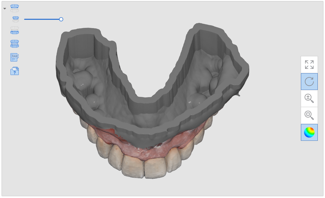
There are numerous reasons for this. Clinically, you want to scan the jaw with the implant without the scanbody in place so that you can have access to the contact areas of the adjacent teeth. More importantly, the scanbody can be taller than the adjacent teeth, which would throw off the buccal bite capture when trying to relate the upper jaw to the lower jaw.
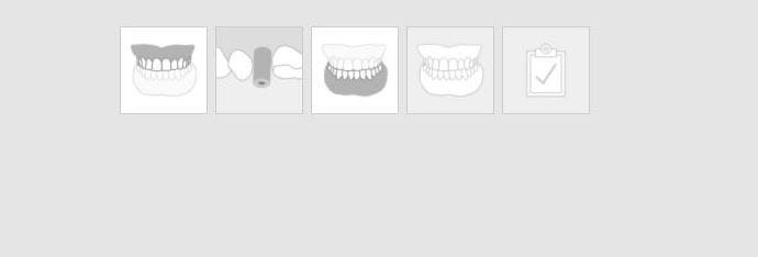
When you image the scanbody in the the Medit iScan software, the data is ignored for the occlusion calculation. When you, or a lab design with the scanbody, they also have to “feed the CAD Software” the right information. 3Shape software requires that 3 models be imported in a specific sequence: the jaw, the jaw with the scanbody ALREADY merged, and the opposing. If the designer is a novice, they may struggle with this and reject your case. There are numerous work arounds and easy fixes for this, but a good practice is to image them separately for all the benefits outlined above.


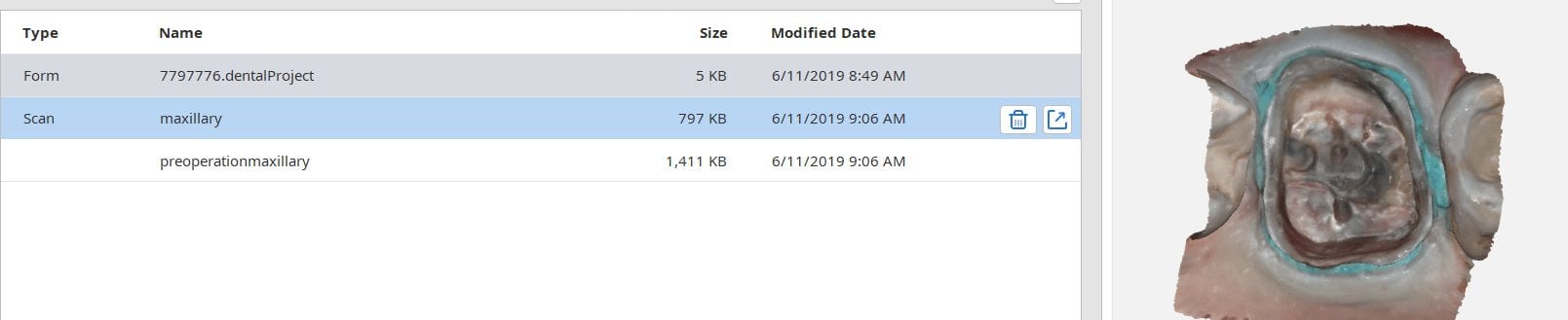
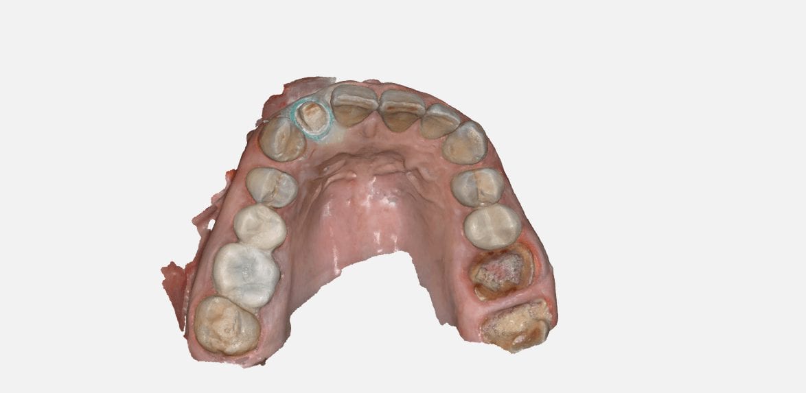
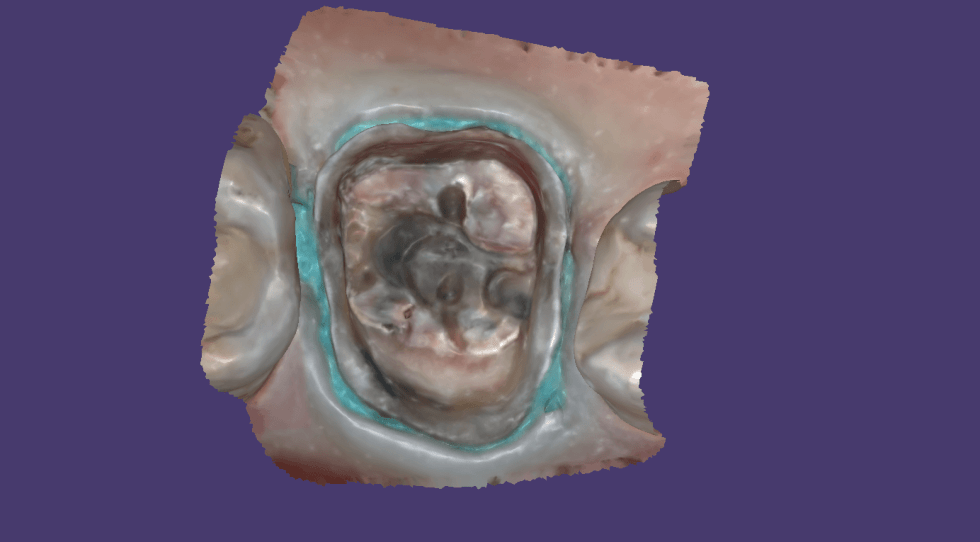
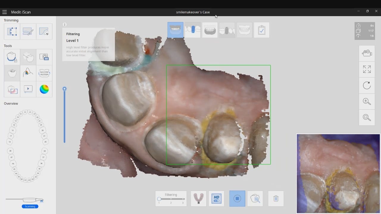
This article is for advanced users, where we detail a quick and easy scan, design, and mill. While the patient is anesthetized, the preop images are scanned. Excess data is removed as all it does is slow down processing. The prep catalog box is clicked, and the same model appears there. This is a source of confusion for many new users. Therefore, we recommend that you immediately crop out the area to be prepared so you don’t get the catalog boxes confused.
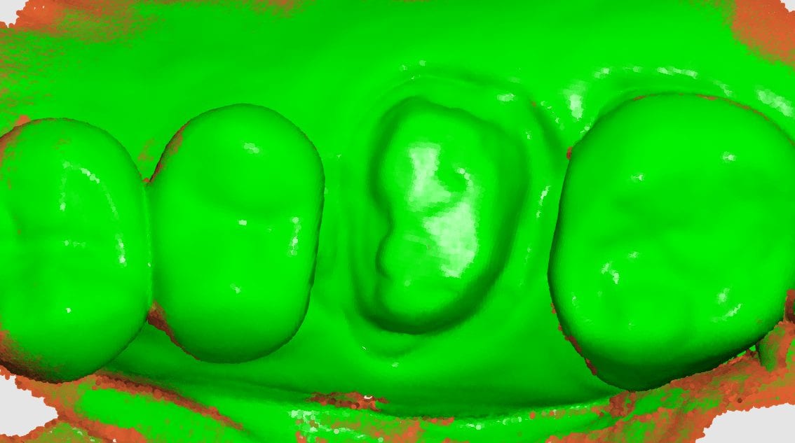
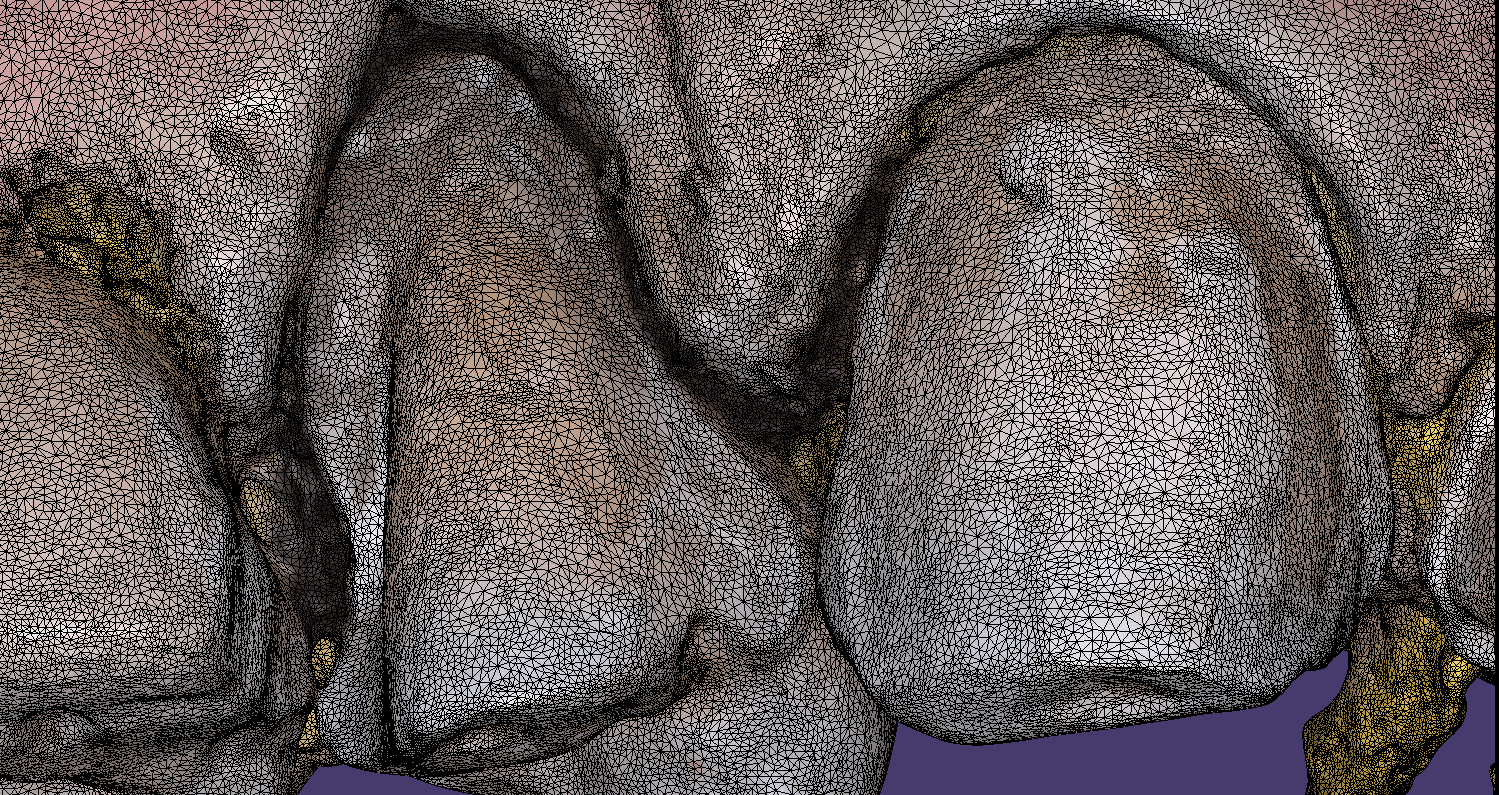
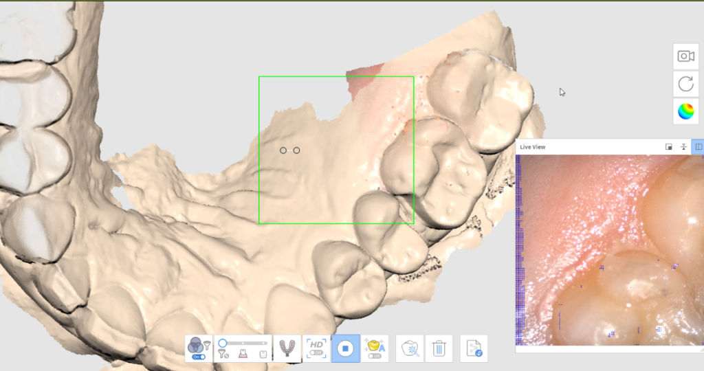
As an advanced user, you may be familiar with the reliability map. Here, we demonstrate how you can use the reliability map to capture your margins. Once the data turns green, this means you are done creating the model. This does NOT mean you captured your margins correctly. You could have just as easily captured tissue that is hiding your margins. The live view, in the bottom right corner, is where you can clearly asses if you have direct line of site to your margins!
Furthermore, as an advanced user, you may realize that it is NOT necessary to capture data below the height of contour of the adjacent teeth as you will not be making contact with that area! You can see in the try-in video at the end of the article how the restoration fits well to the contact area of the neighboring teeth even though the data was not captured.


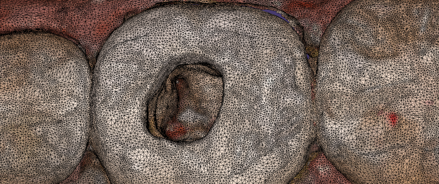
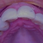
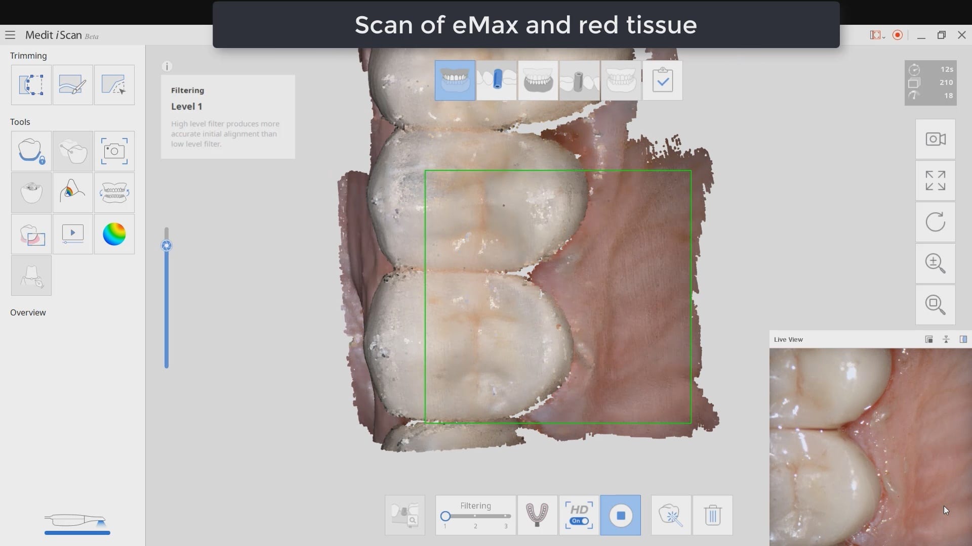
Imaging depth and red tissue or blue can be complicated for all intra-oral scanners. In this demonstration case, we show how the Medit i500 performs scanning inside the canal space of a lower first molar after a pulpectomy. The dry canals are readily picked up by the scanner at a focal length of 21 mm. The bleeding from the distal canal space makes it a bit more challenging to capture.
Medit i500 uses two cameras that operate at different filter levels of color spectrum. The camera was changed from blue (great at capturing tooth structure) to white camera, which is better at capturing red (soft tissue and bleeding)

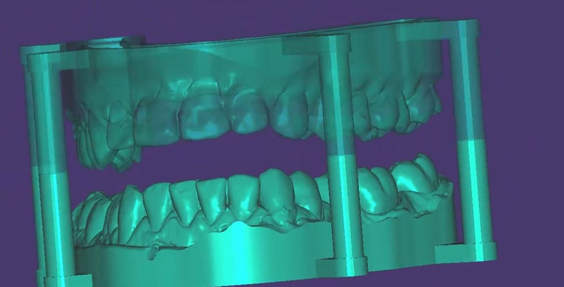
A friendly reminder- this case was table top scanned with a desktop scanner so don’t get distracted, but be aware that for oral appliances, particularly for apnea treatment or bruxism, to be aware of your lab’s capabilities. Many labs will just take your upper and lower scans and print them and hand make the appliances. To combat that, we recommend that you mount your models with support pins and edit / shape data , fill holes, etc,.. before sending it to the lab.
If you are using exocad, don’t make watertight models in the medit software, but do fill in major holes. Exocad doesn’t like closed models when it puts a base and adds support pins. If your lab prints these, at least the pins will force them to mount it in proper orientation

Digital impressions have turned one of the most complicated and error prone procedures in dentistry into one of the most predictable treatments we can provide.
When taking a physical impression of an impression abutment, you need to secure it to the PVS material so it remains rigid during pour ups. Some choose open trays while others prefer closed trays. When you deal with multiple units, their divergence or convergence can inadvertently lock the tray in the patient’s mouth. Sometimes, the impression abutments impinge on each other and keep you from seating them all the way.
That was a short list of the many things that can go wrong. With a digital impression, you can capture the contacts or the adjacent teeth, the opposing, and the tissue profile very easily. You can then place a scan-body and take an impression of it’s position and identify the location of the fixture.
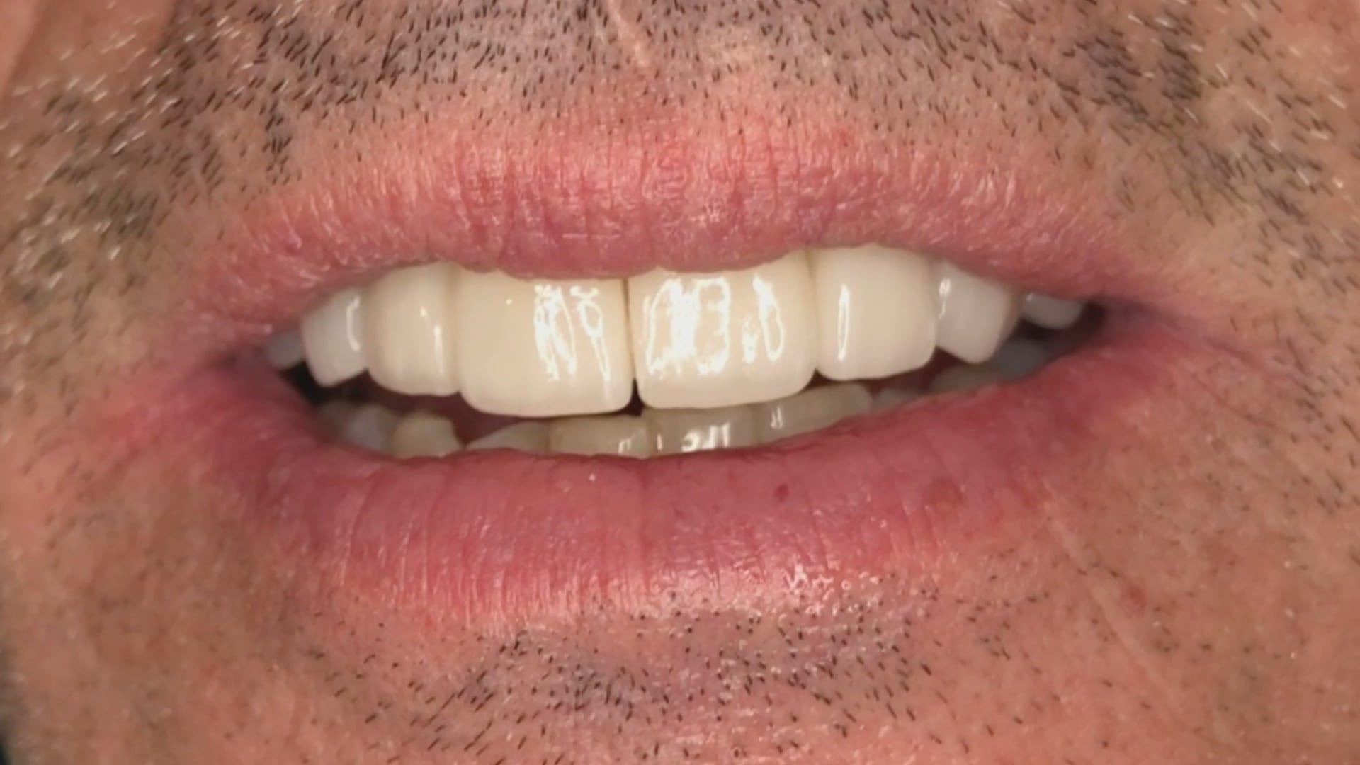
In the following videos you can see the steps involved and how easy it is to manage the impression and accurately capture the implant location.
In titanium blanks, there is only one place to put the sprue, which is on the occlusal. One might think that this is would be easier to manage, but the trouble is that the titanium blank is cylindrical in shape, and it makes it difficult to keep track of the implant hex position and proper indexing.

There is one important matter to keep in mind when digitally designing an implant abutment for milling from a pre-milled blank. Unlike regular restorations you can design a restoration in (CAD software) and position it in a block , place a sprue in a desired position, and mill (CAM software) the final product.
The solution is to provide data to the milling machine so that it can properly index the titanium blank. To keep it simple, a regular restoration can just be milled from a designed stl file. The titanium pre-milled blanks need accompanying files to the designed stl to properly mill the abutment for indexing purposes. In exocad software, there is a construction file that accompanies the design and the CAM software can read both files and produce a desired result.

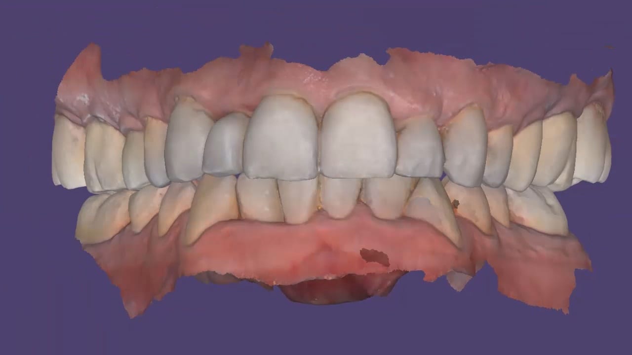
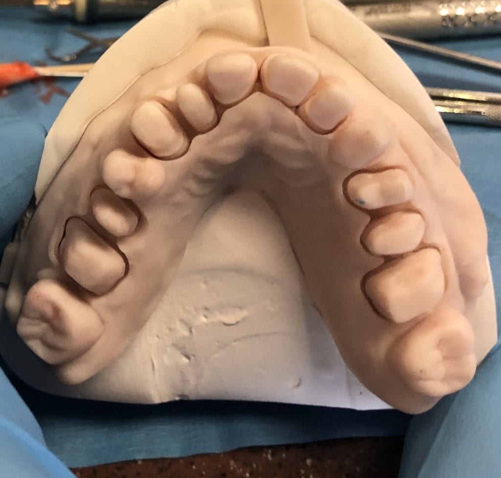
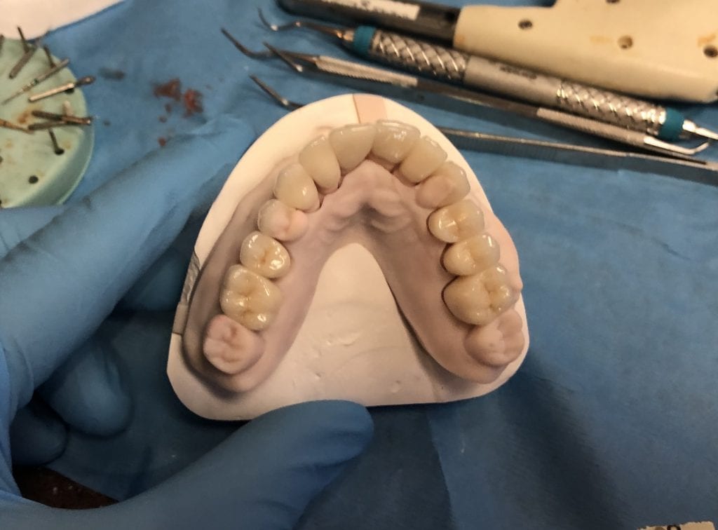
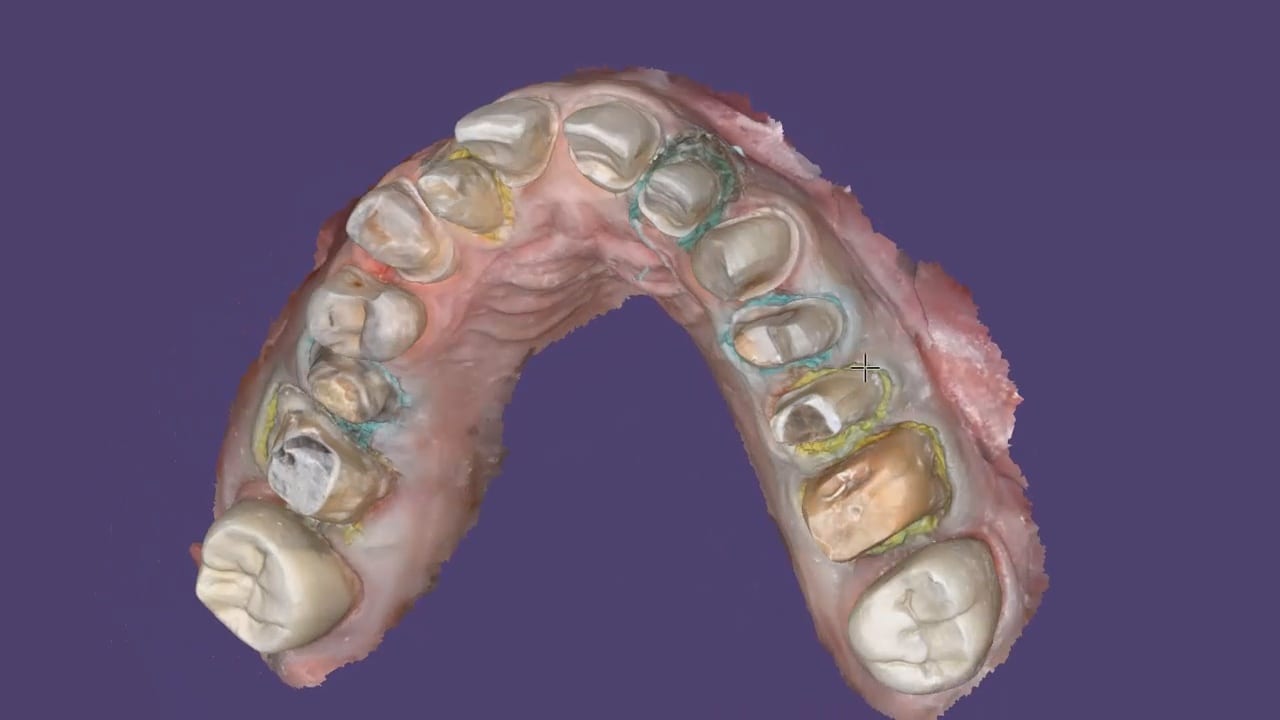
In all of our courses, once every user gets comfortable with the software and the camera, we quickly ramp up to reveal the greatest advantage of digital impressions over analog ones. The premise is that digital impressions can create models of data (note the deliberate omission of words like teeth, tissue, etc.) that are independent of time and sequence, and moreover, you can edit or manipulate the captured information.
In this particular case, we demonstrate how the upper anterior eight were prepared and how the preps were captured over an extended period of time. You can appreciate how one case protect margins and preparations from introducing subsequent errors. You can also visualize how you can create models without following a certain pattern.
Once you understand this concept, you can apply multiple ways to tackle the most complex and comprehensive cases and treat them with ease. We would love to host you at one of our courses to teach these principles and how you can take ANY intra-oral scan from any device, take it to CAD software, and take it to ANY milling machine you want. Oh yeah, we can also teach you how to introduce CT data into the mix from any machine to handle an even bigger case.
Click on our courses and events to see future courses. We’ll be adding more dates very soon.
Separate from how we imaged the arches, we think the perfect place to “hand off” a case like this is when you have mounted your upper and lower jaws, the opposing, marked margins, and set the path of insertion. At this point, as a clinician you have provided all the information needs to proceed with the case.


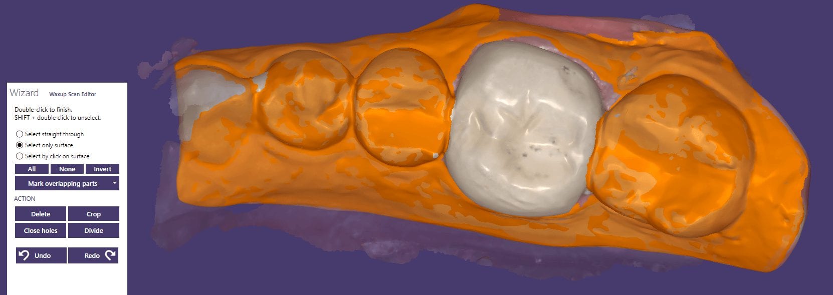
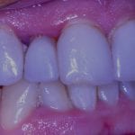
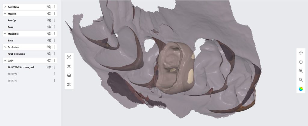
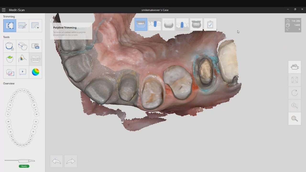
In this simple first molar case, we scan the pre-op condition as there is no room to add any contours to the pre-existing crown. In the video below, you can see how it occludes with the opposing and how it contacts the adjacent teeth. A pre-op scan is taken and the crown is removed. Images of the recurrent decay are taken and the preparation was modified. Final impressions were taken after tissue retraction and hemostasis.
The pre-existing condition must be trimmed away and you want to keep only the areas you want to make contact with in the proposal. This simple method gives you instant proposals where you only modify the contact areas and proceed to production


In just under a decade, we have turned dental implants from the most risky and stress inducing procedures we can perform both surgically and restoratively into one of the most predictable procedures we can perform while drastically reducing the cost of care, whether you fabricate the prothesis yourself or outsource it to a lab.
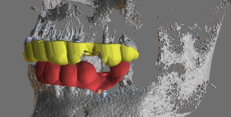
With guided surgery, the benefits are immeasurable. One good argument is that clinicians can avoid certain surgeries while discovering physical limitations during the planning stage. Furthermore, if performed fully guided, once can generally place the implant exactly where it was digitally planned in 3D on a CT scan.
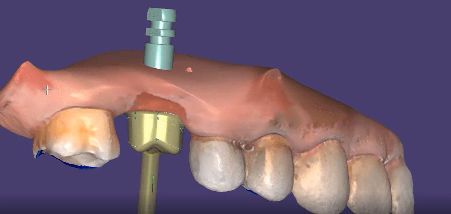
Restoratively, we also have some tremendous advantages; whether you are performing single units or multiples, digital impressions give you an advantage you never had with physical impressions. In this first video, we emphasize how you and your team should take picture of the scanbody that is being used during the digital impression. It is very easy for you or the lab to mistakenly label digital impression in the design software.
The great benefit of digital impressions is realized when you can capture all of the contact areas of neighboring teeth. Furthermore, you have the ability to digitally sculpt the soft tissue and create the emergence profile for your abutment. When you take the soft tissue profile, the position of the head of the implant, and the contacts of the adjacent teeth into consideration in your design, you stack the odds of a successful restoration into your favor

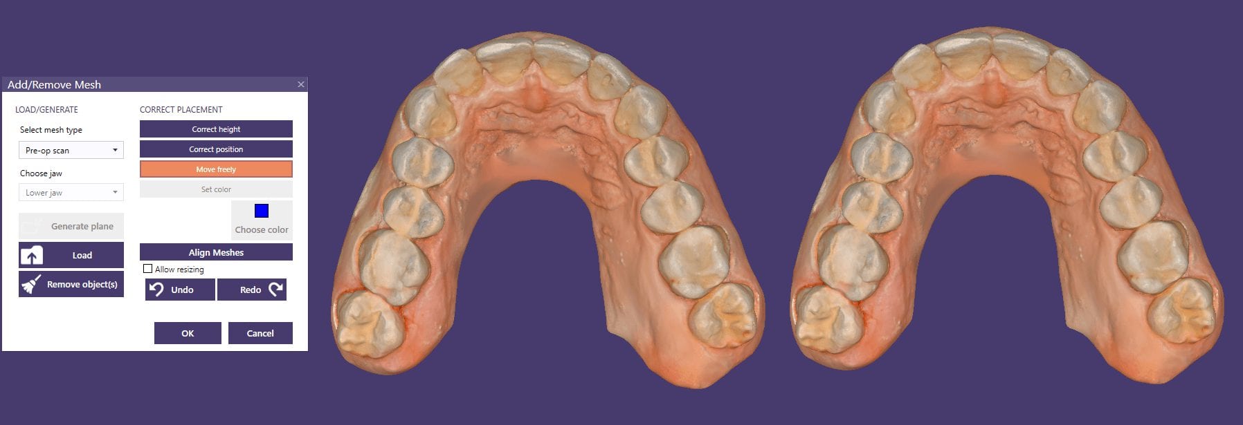
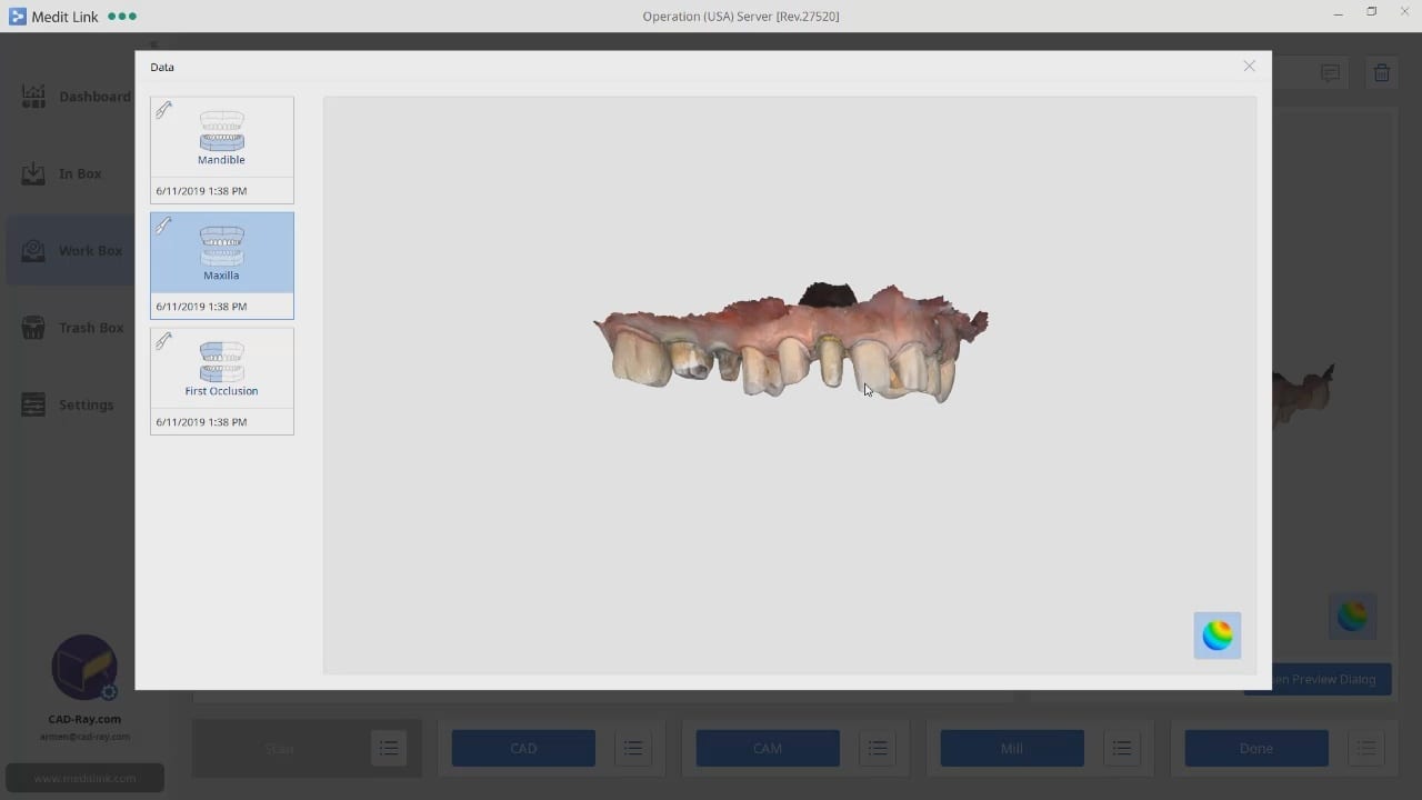
This case demonstrate some advanced features our CAD-Ray software provides for CAD/CAM users. We first launch meditlink and define the prescription. You can take your time and input your selection at this step, BUT we give you the opportunity to edit it when you launch the CAD software.
You will note that after the imaging is done, the CAD software is launched which allows us to change the job definition. You have two choices for utilizing the pre-op condition with our software; you can either use the pre-op as a reference frame for your design or you can copy it exactly as a replica. The latter is called “Digital Wax-Up” for exocad users.

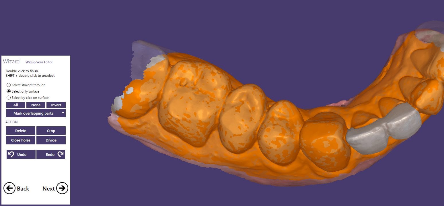
What we have done is to program the software and its wizard to get you from the model step to instant proposals after you place your margins. We guide you through the steps and ask you to trim away anything you don’t want your proposals to replicate and to only leave behind a shell of the exact form and function you want to keep in your proposals. This instant proposal is a dream for most dentists. It is the quickest way you can get to a design and to fabricate a restoration

The CORiTEC one can handle multiple types of blocks. It is also upgradable to pucks to mill round house prosthetics.
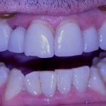
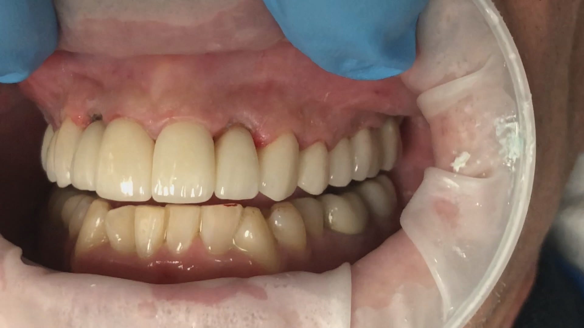
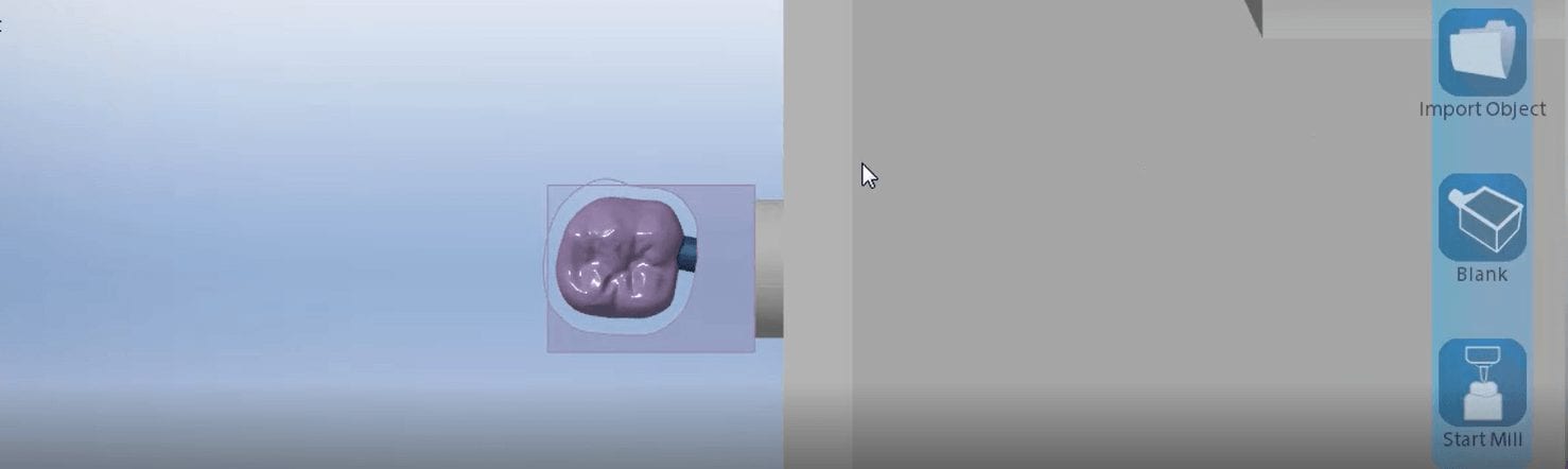
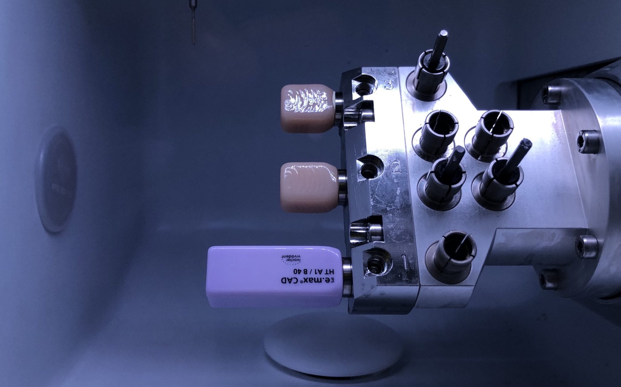
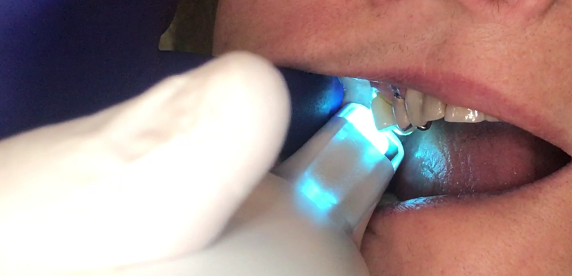
In this video, we demonstrate the milling of a 40 mm emax block. The machine can also handle 60 mm emax material. The height of the block is also important. In this particular case the Incisal edge would not fit in the confinement of the block dimensions. The margins were milled and then a little bit of layering material was added to the block

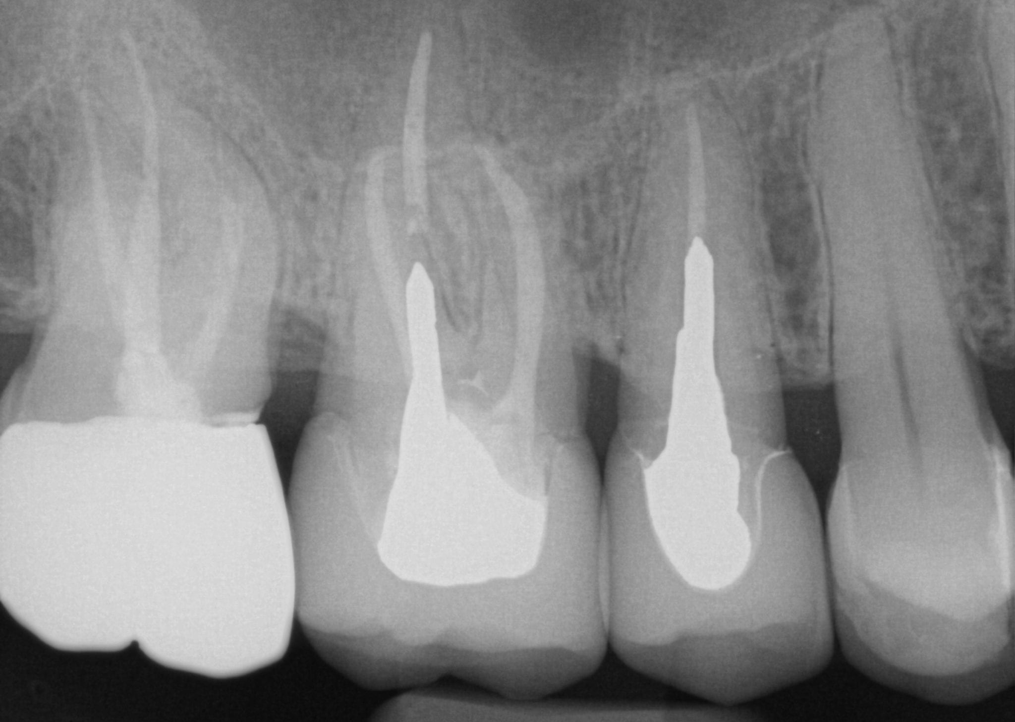
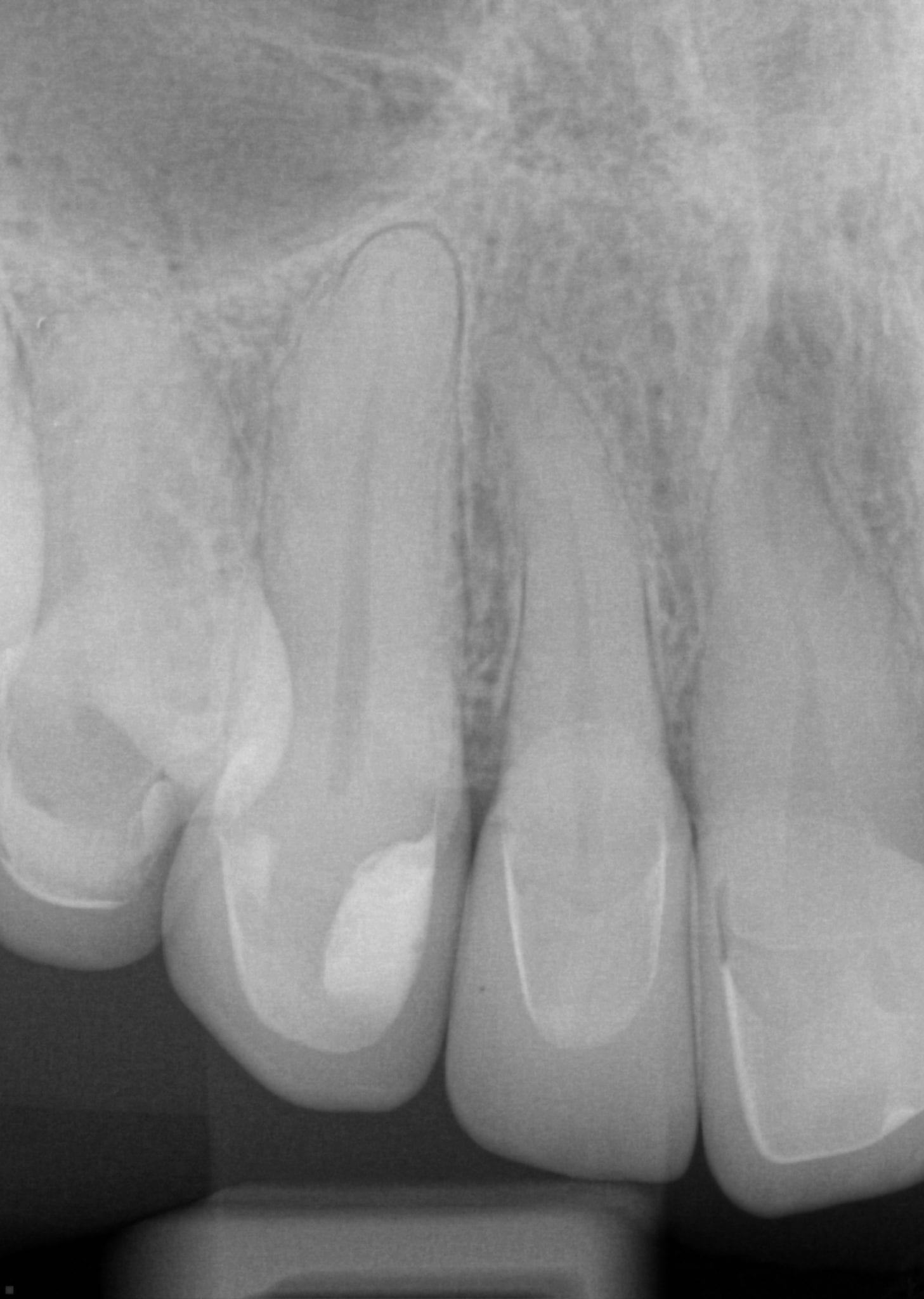
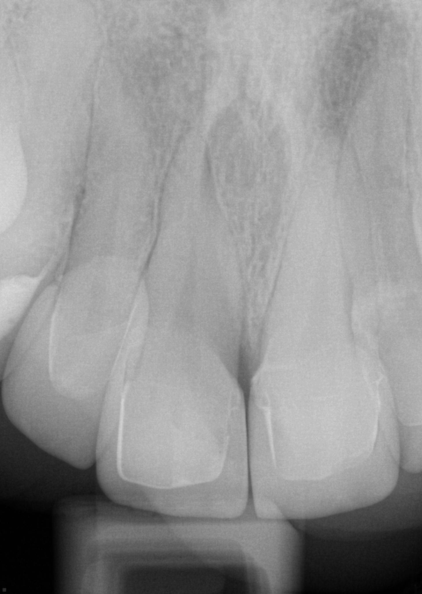
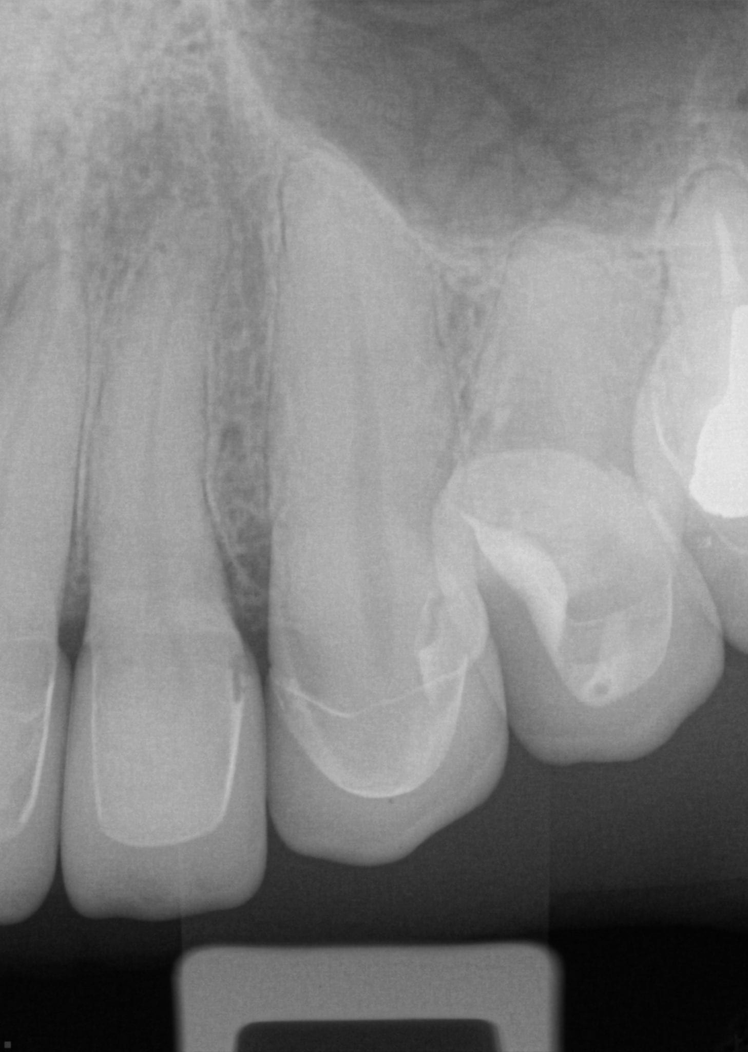
Try-in bitewing X-rays of crystallized emax


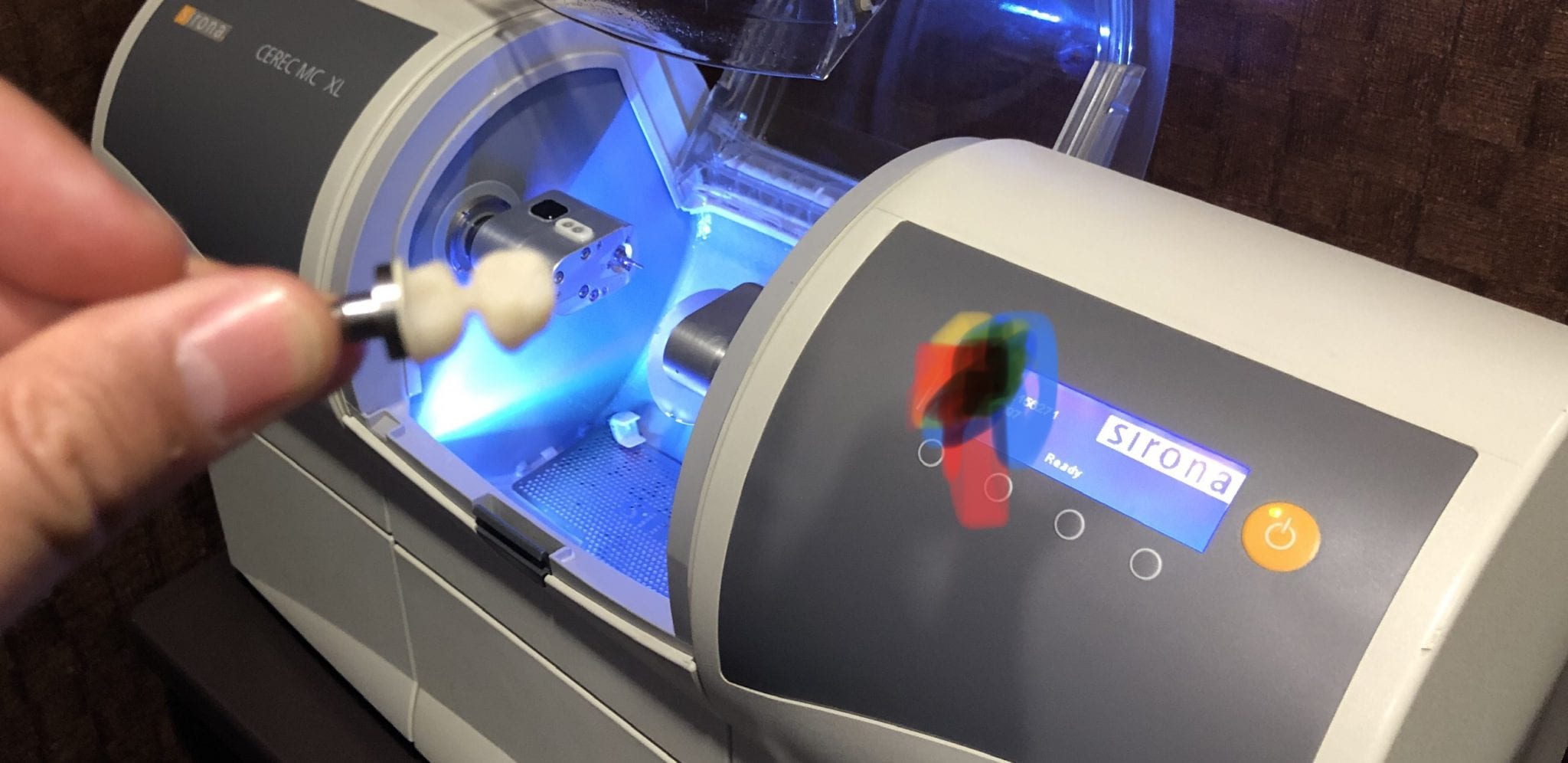
At any given time, we are milling restorations with 3 or 4 milling machines. Recently, we designed a restoration with the Medit i500 scanner, designed in exocad, and milled with a chairside mcxl cerec milling machine. Here are the steps we took to do this:

You can contact Mr. Milos Gedosev who runs DentalCADCAM in Germany and has earned a great reputation over two decades if you have any questions.


In this video we demonstrate how to capture implant impressions of scan bodies intra-orally with the medit i500 scanner and then design a screw retained crown with our customized CAD-Ray software.
The sequence of steps for a new user are critical. Although it doesn’t matter if you image the opposing arch first or after the arch that is being restored, the steps to capturing the scanbody must be followed in chronological order. You must capture the arch and then the scanbody impression. You should not return to the arch catalog box and add any more data. This can introduce a lot of error in the processing steps
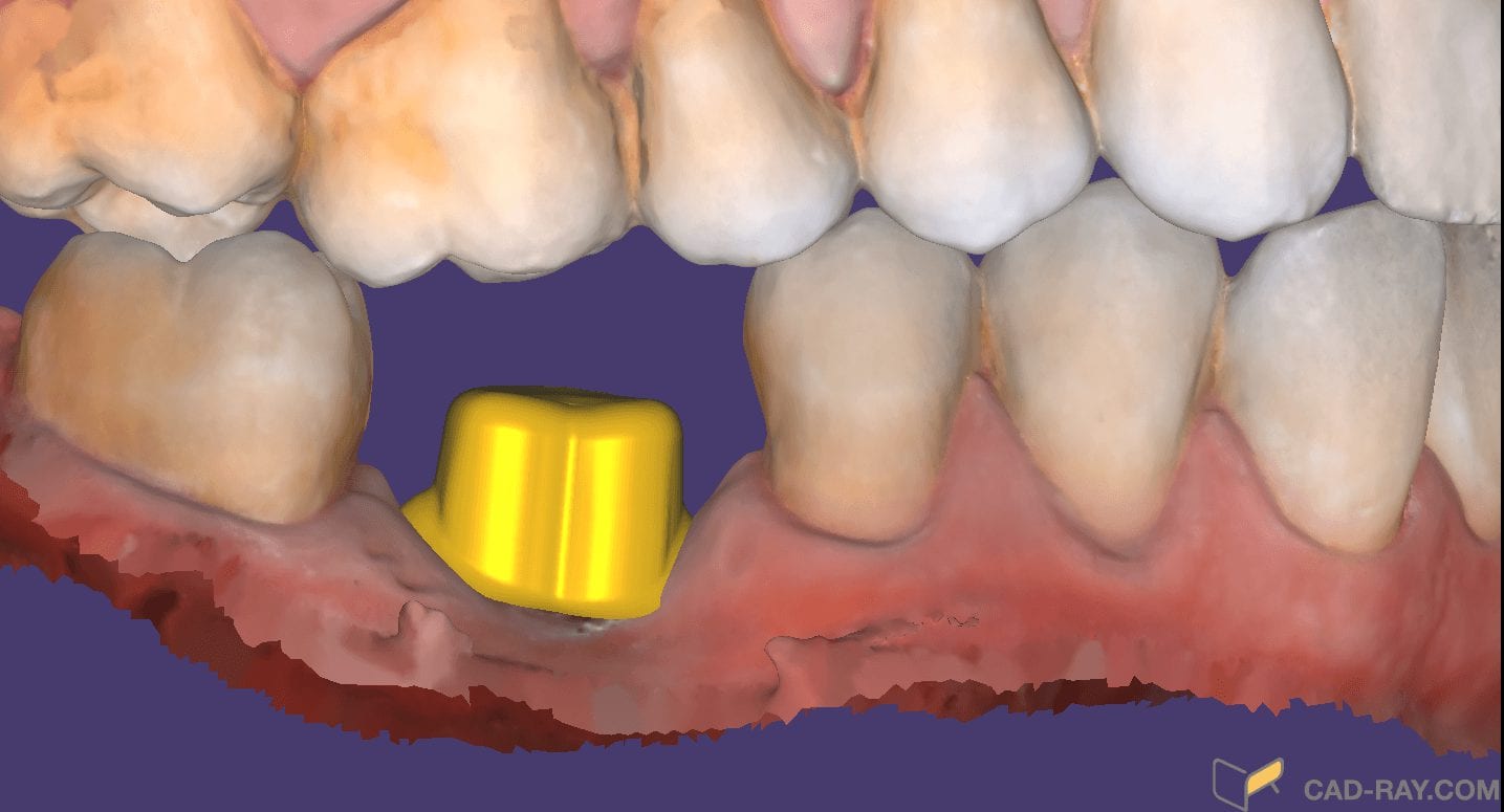
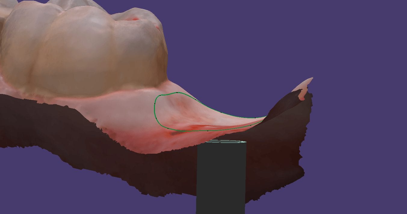
In this video you can appreciate the distinct advantage you have tissue training on a digital model. You can contour to the soft tissue very easily. It is best to do so after you have identified the scanbody, which will pinpoint the location of the fixture. Once you have that in the equation, you can sculpt your tissue to your liking, making sure your abutment margins never drop apically below the head of the fixture

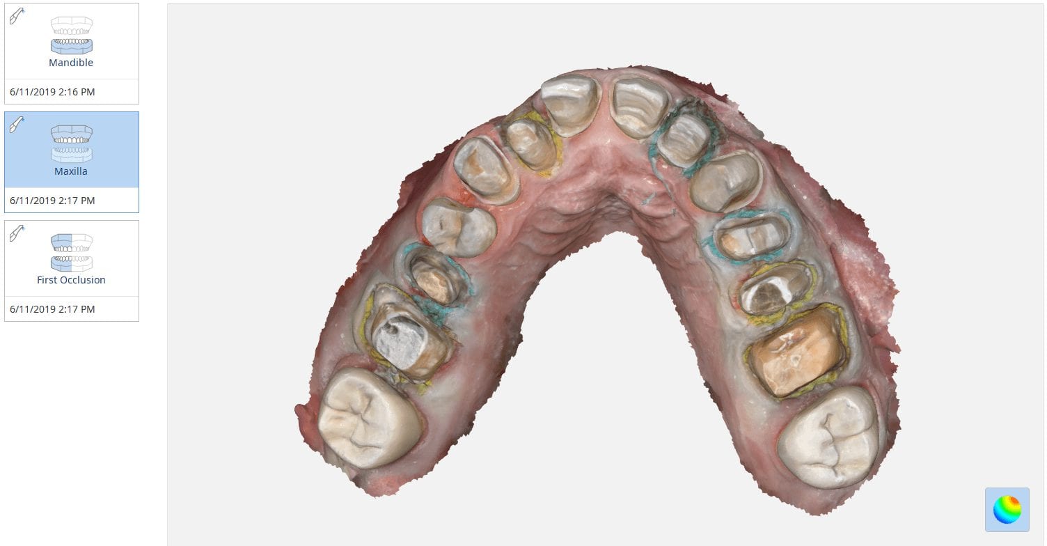
If you are new to digital dentistry, this introductory video will show you how to judge if digital models are related to each other. As a simple exercise, we opened one digital model and then imported the exact same model as a pre-op scan into the equation.
Once the models are in the design software, they are manually related to each other with at least 3 common points. After the merge, we performed “best fit matching” and then demonstrate how the color histogram in exocad has the both models painted completely blue.
We then slightly altered one model by adding material to one cusp tip, reduce the adjacent cusp tip, and then smoothing the third cusp tip. We then re-aligned both models to each other again and you can see how the software lets you know the range of discrepancy in those areas. Notice that all three areas have the same histogram color but all three have distinct meshwork areas from the original.
Once you understand this concept, it opens up many avenues for you that you can never achieve with traditional impressions.

You must be logged in to post a comment.