


Click to Download the Lower Arch Model OBJ file
Digital Dental Impressions with Intra-Oral and Desktop Scanners
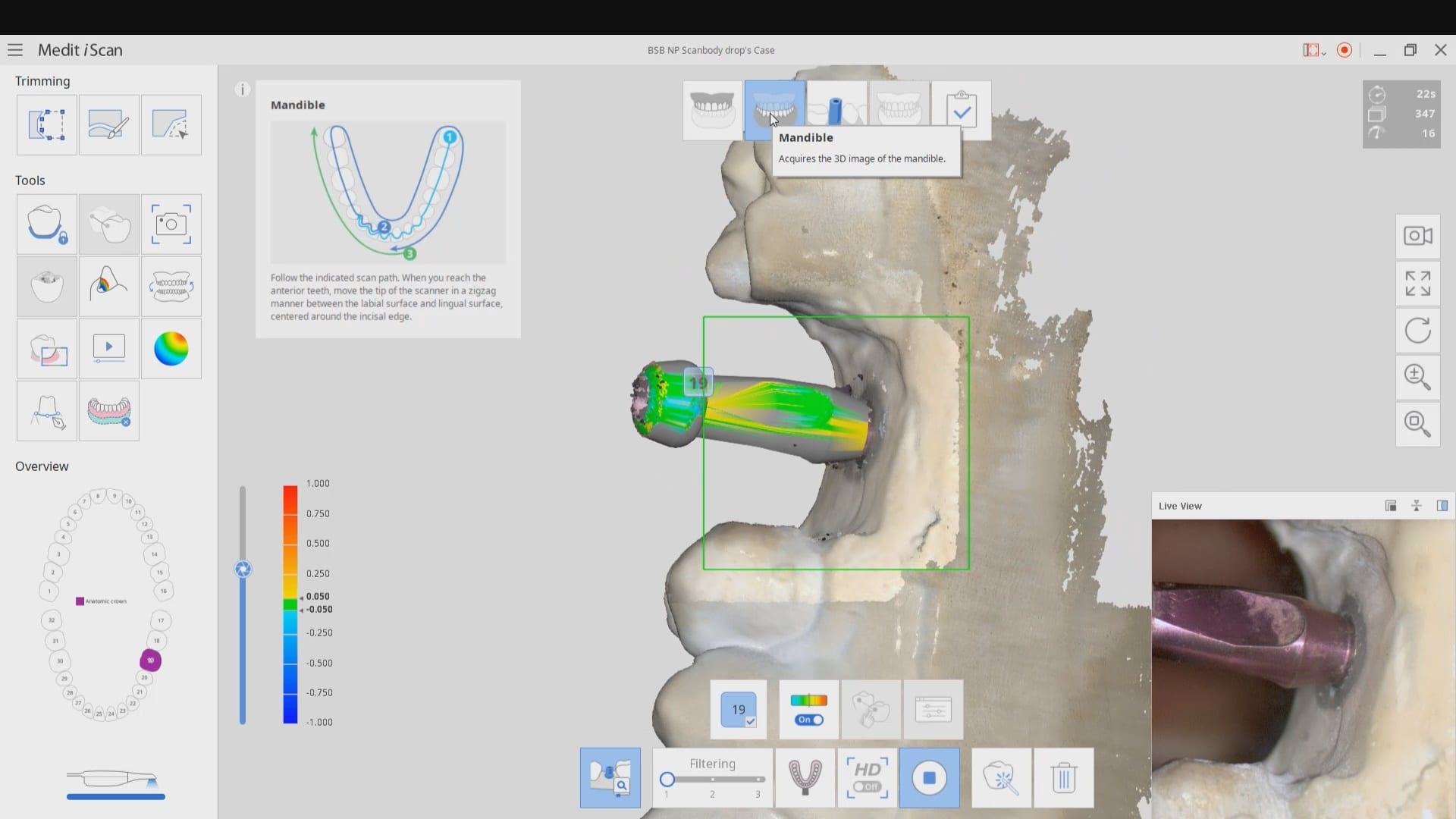
Medit has launched a software that is the greatest advancements in digital dentistry in more than a decade! With artificial intelligence, you can identify the scanbody during intra-oral digital scans. This has many implications for accurate scan captures and skipping multiple steps in the design process in CAD software like exocad.
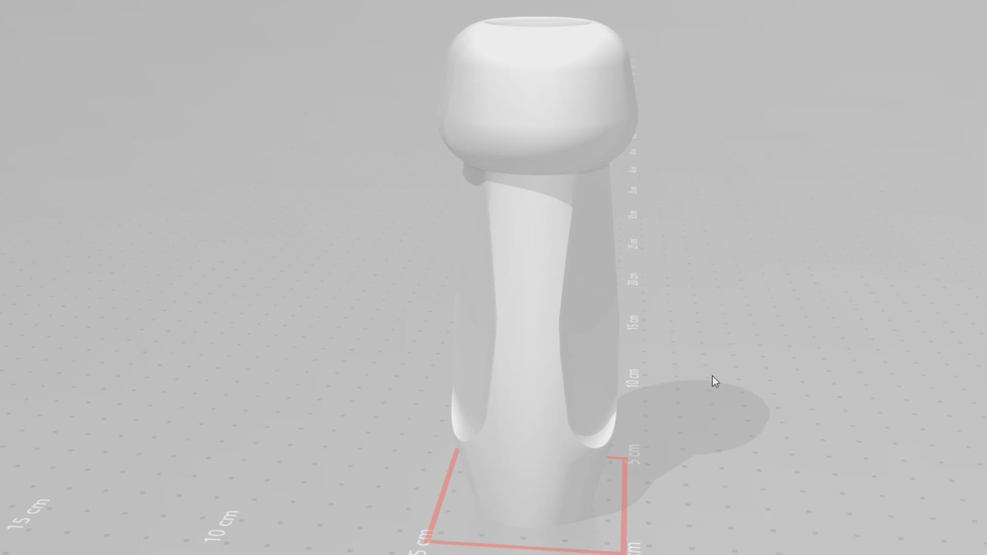
But there is more! This will knock your socks off. You can build your own custom library for scanbodies or you can use geometries of abutment libraries from your favorite implant line. In this article we show how to import the stl file for a physical impression abutment (Closed Tray- Blueskybio Part #MIJH) and use it as a scanbody. Just watch the following videos
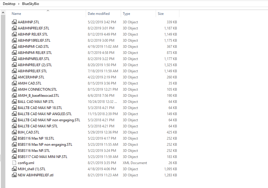
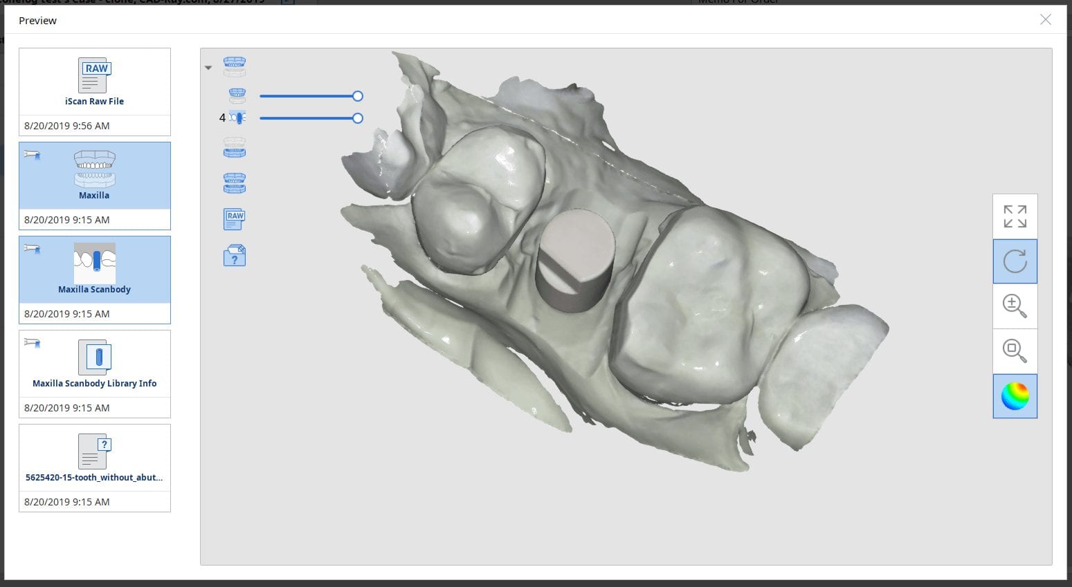
A lot of implant manufacturers will readily distribute their libraries of abutments and scanbodies. Here, we just chose the MIJH impression abutment and previewed it in one of the many free 3D viewer programs included in windows 10.
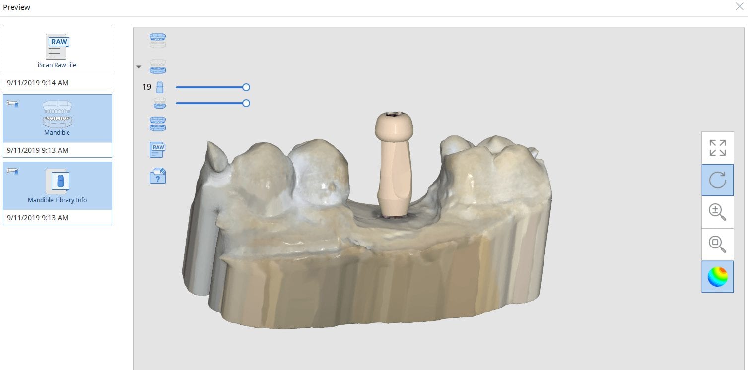
Once the data is imported into the library, you can preview it and incorporated into your own library of abutment. Please note that the abutment libraries are stored in the arch catalog boxes while the scanbody libraries are stored in the scanbdoy library, which means the abutment itself may be taken into consideration when capturing the buccal bite.
Once the abutment is identified in Medit it is directly transferred into cad software like exocad to proceed with design. Note in this footage how little of the physical abutment impression was brought into cad software. This greatly reduces errors and your imaging time intra-orally. You can also place a stock abutment and scan it in the same manner and be able to find margins with great ease without having to reach hemostasis or good tissue retraction
CLICK TO OWNLOAD THE MUA LIBRARY

DOWNLOAD THE BIOMAX NP LIBRARY
![]()

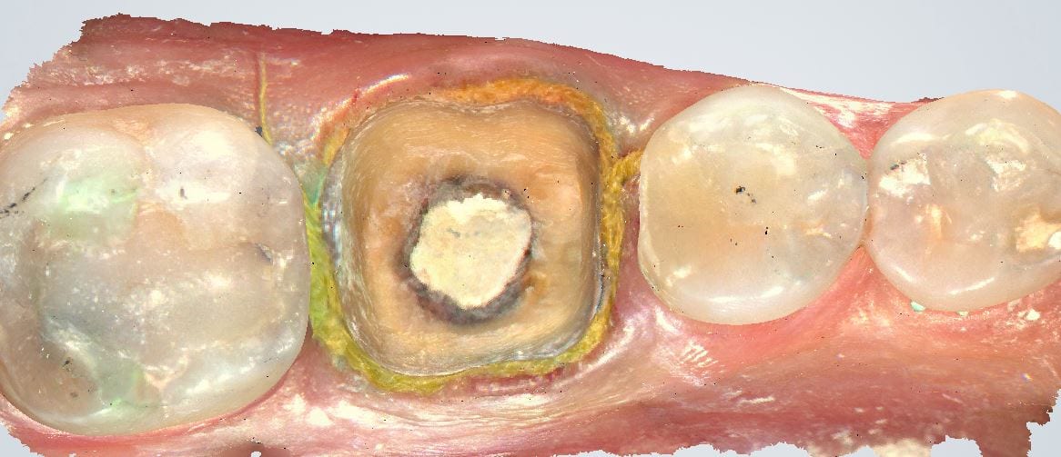
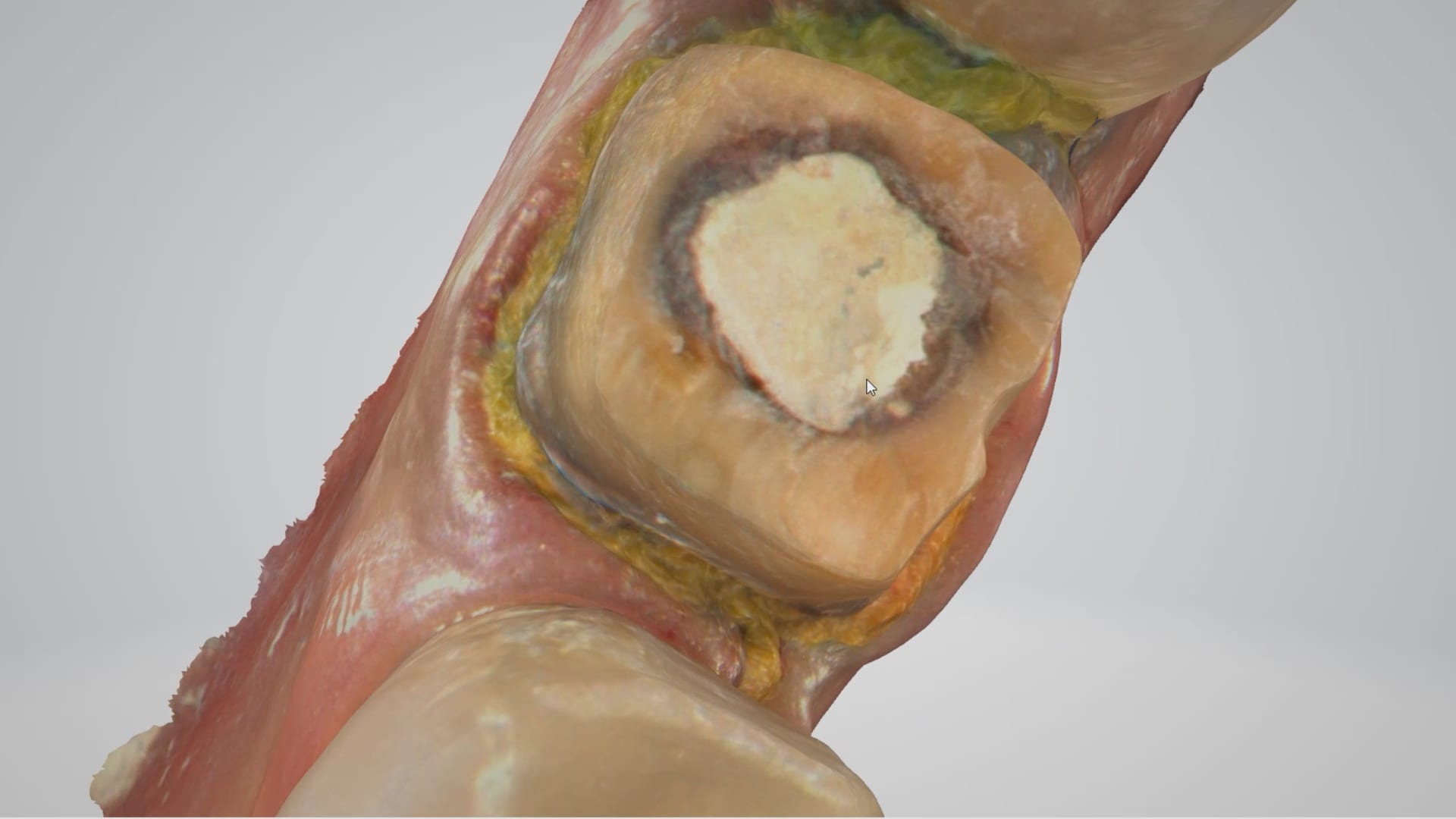
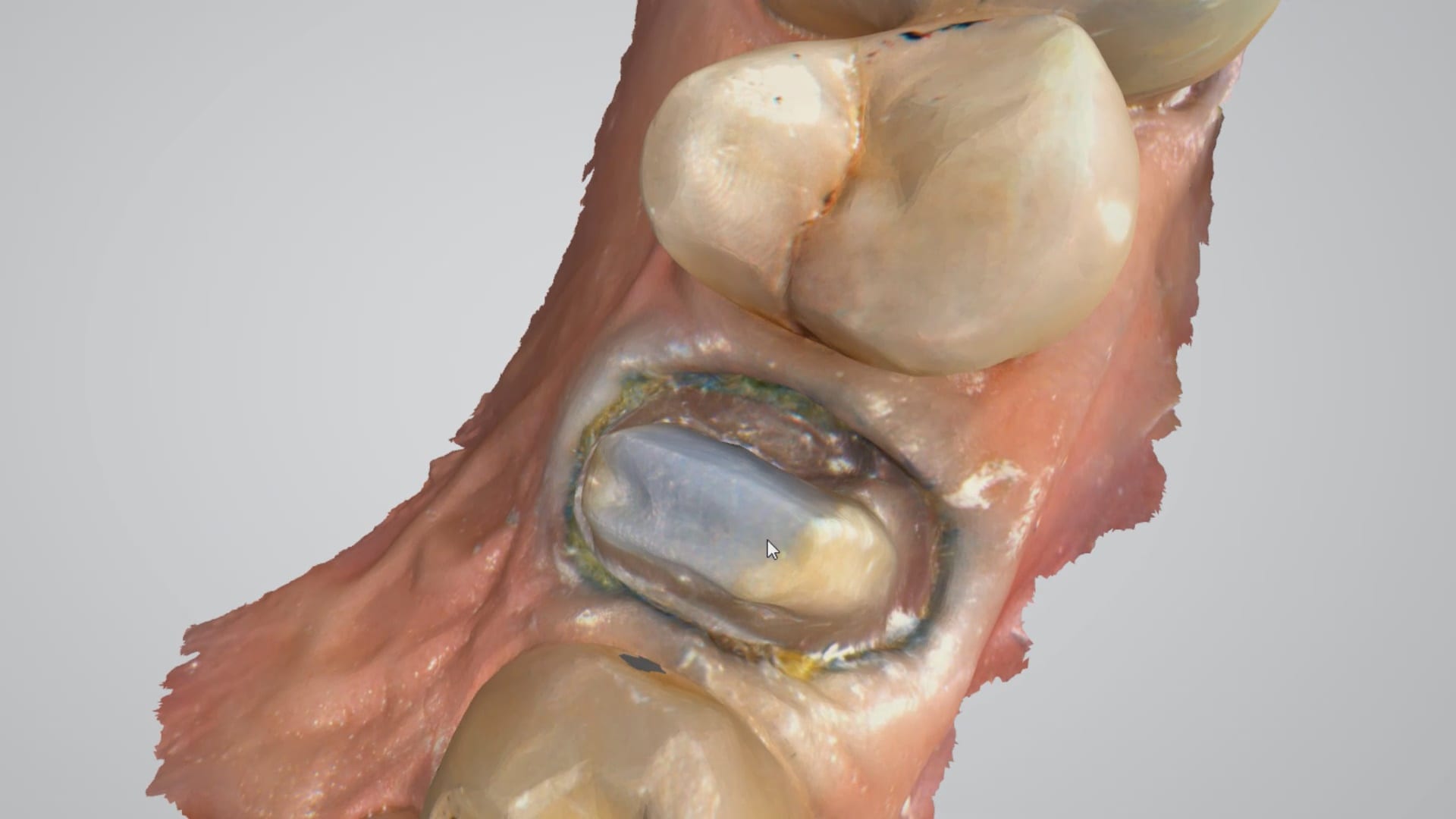
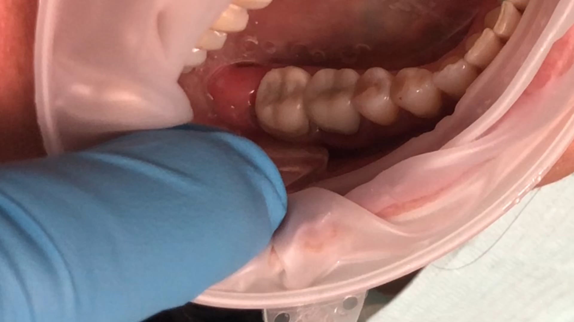
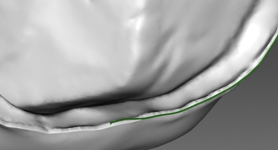
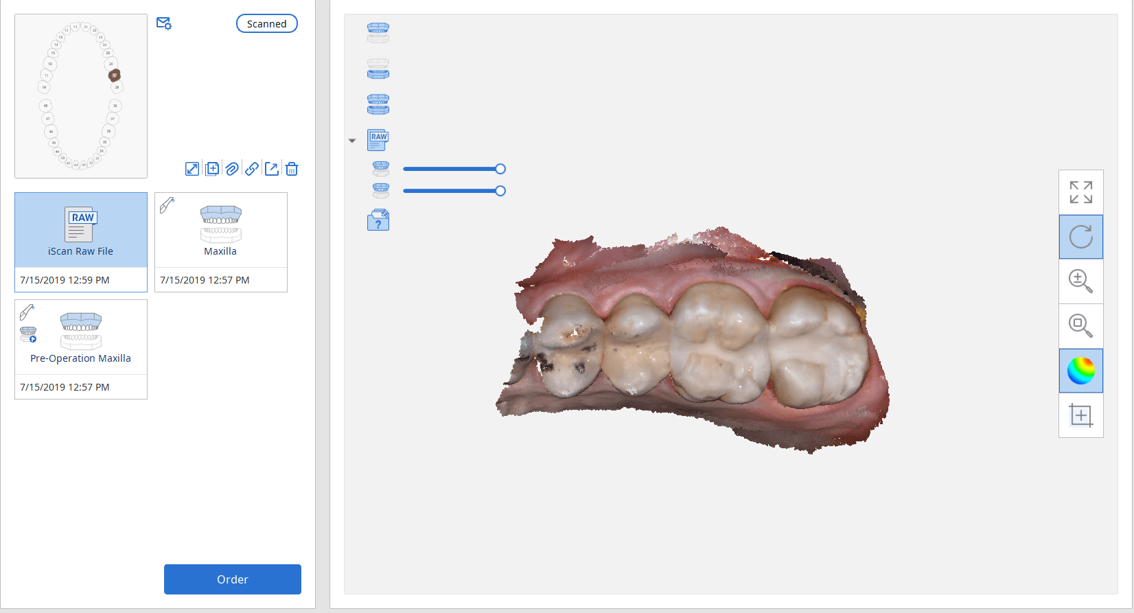
At CAD-Ray, we are big proponents of open architecture and the doctors control the flow of their patients’ digital data, whether it is a CT scan or an digital impression system. We have put the Aoralscan through a battery of tests. For single unit, it delivers on quality that equals any other scanner on the market. We were particularly impressed with this deep margin and how well the graphics could differentiate tissue from tooth structure on the distal of the prep
click to download the OBJ file of this case (note: we only scanned to pick up data for the margins)

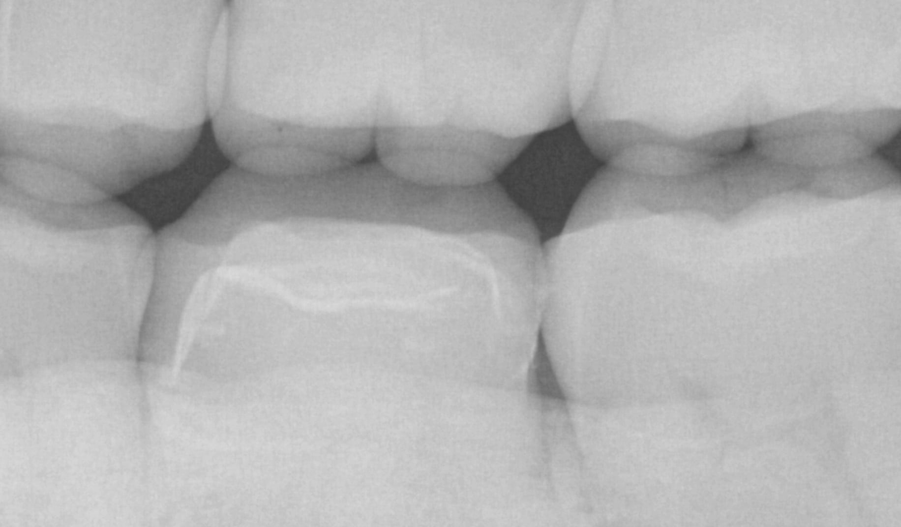
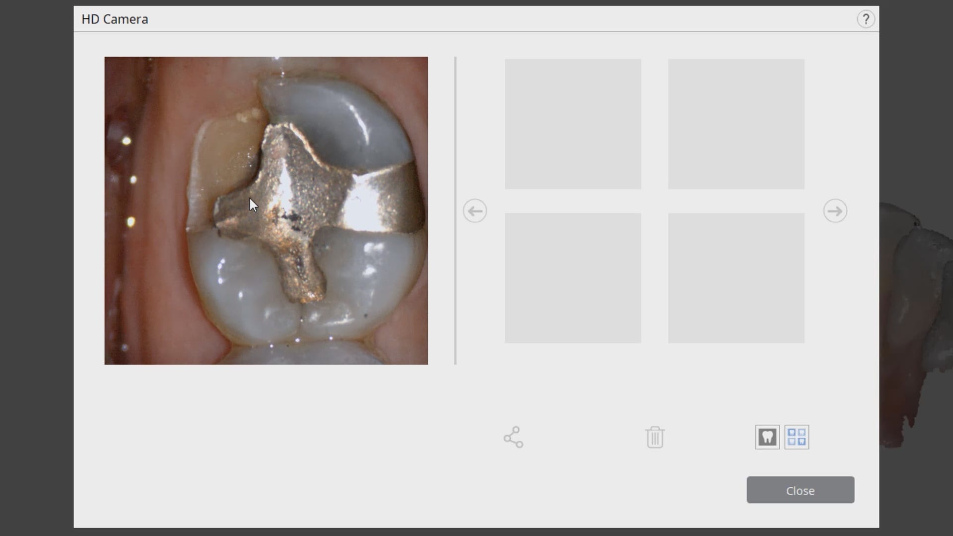
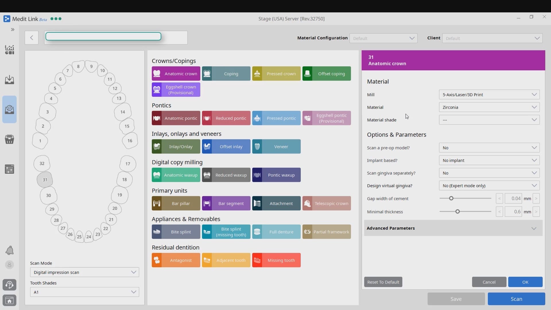
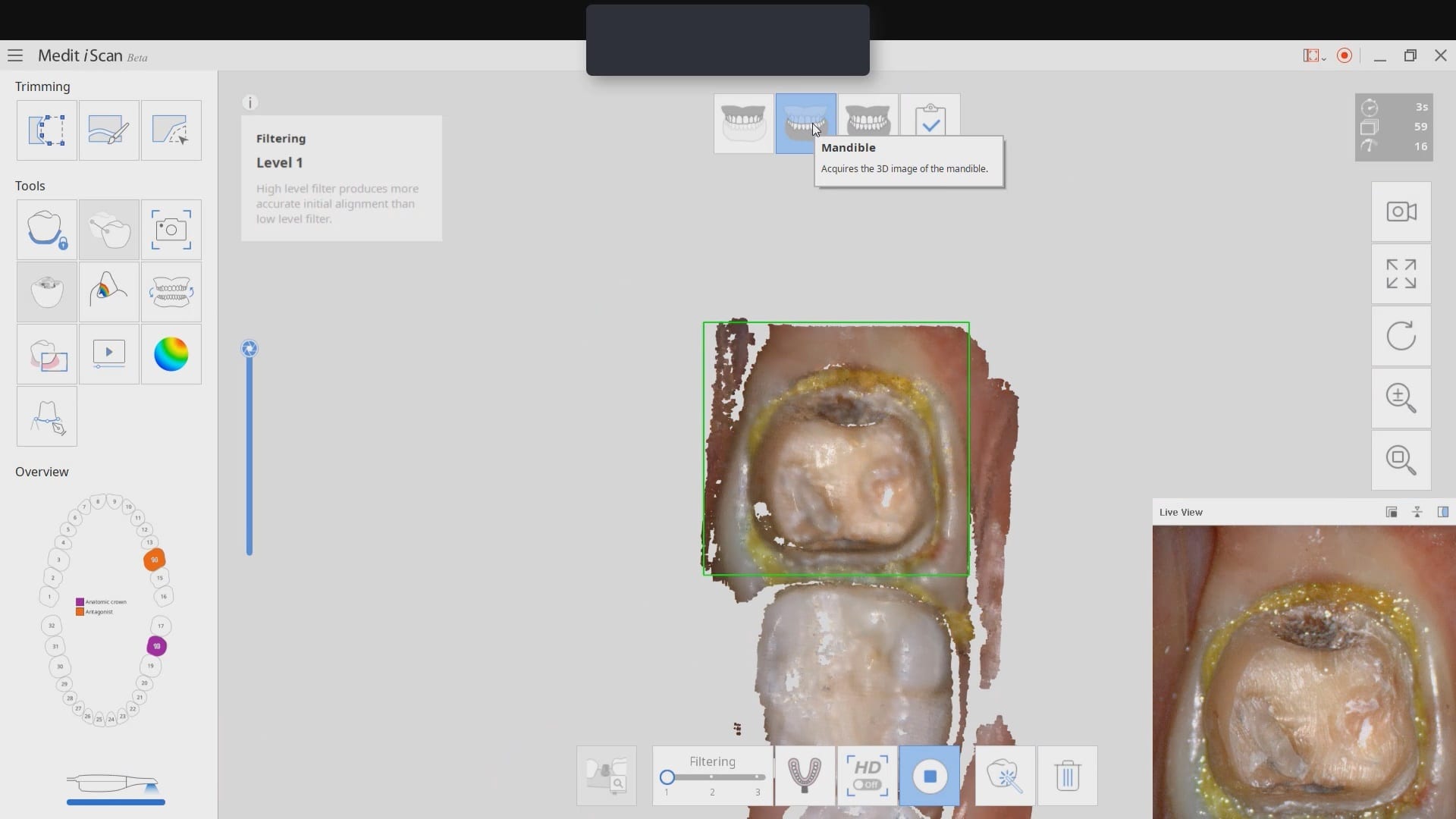
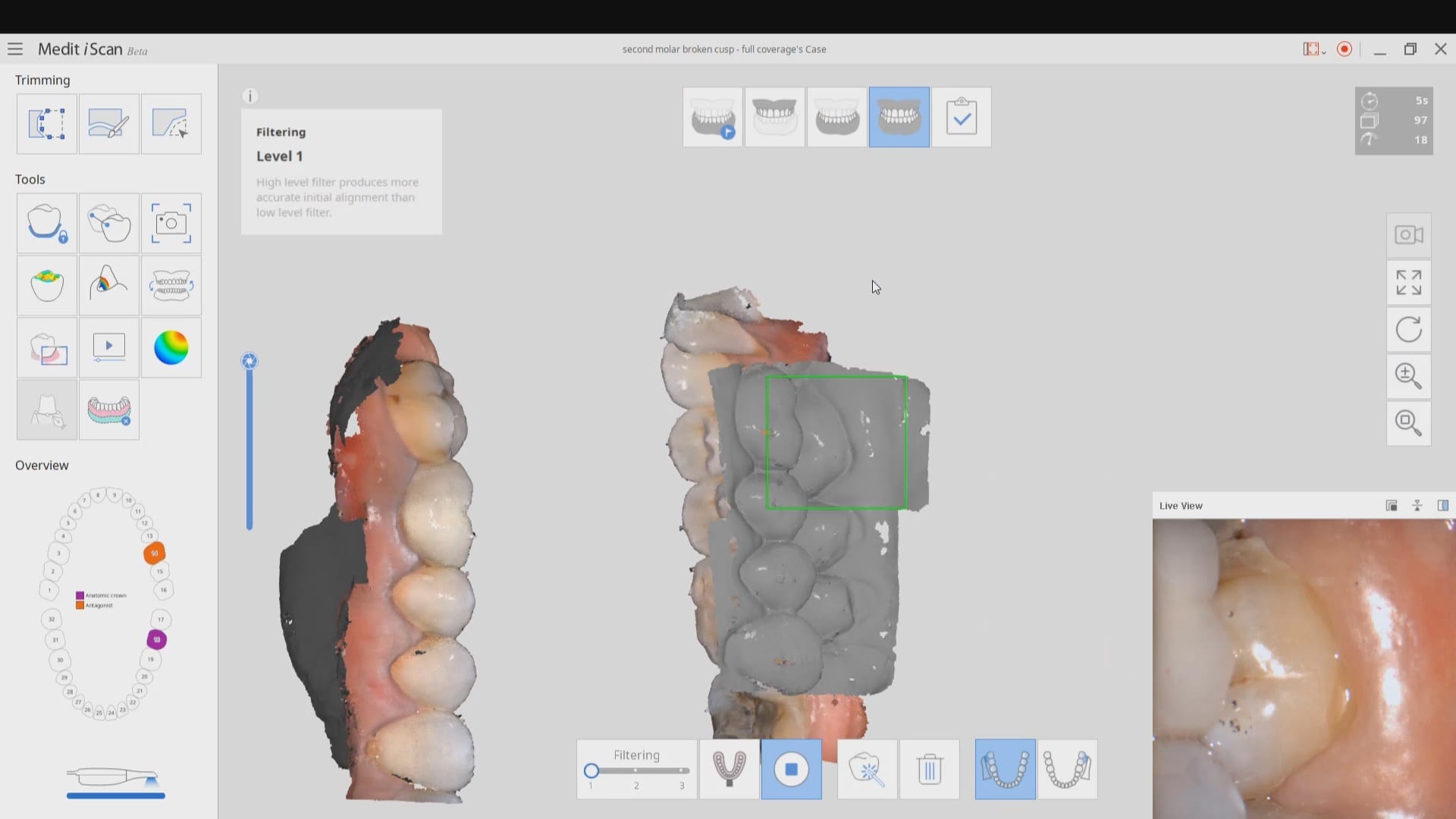
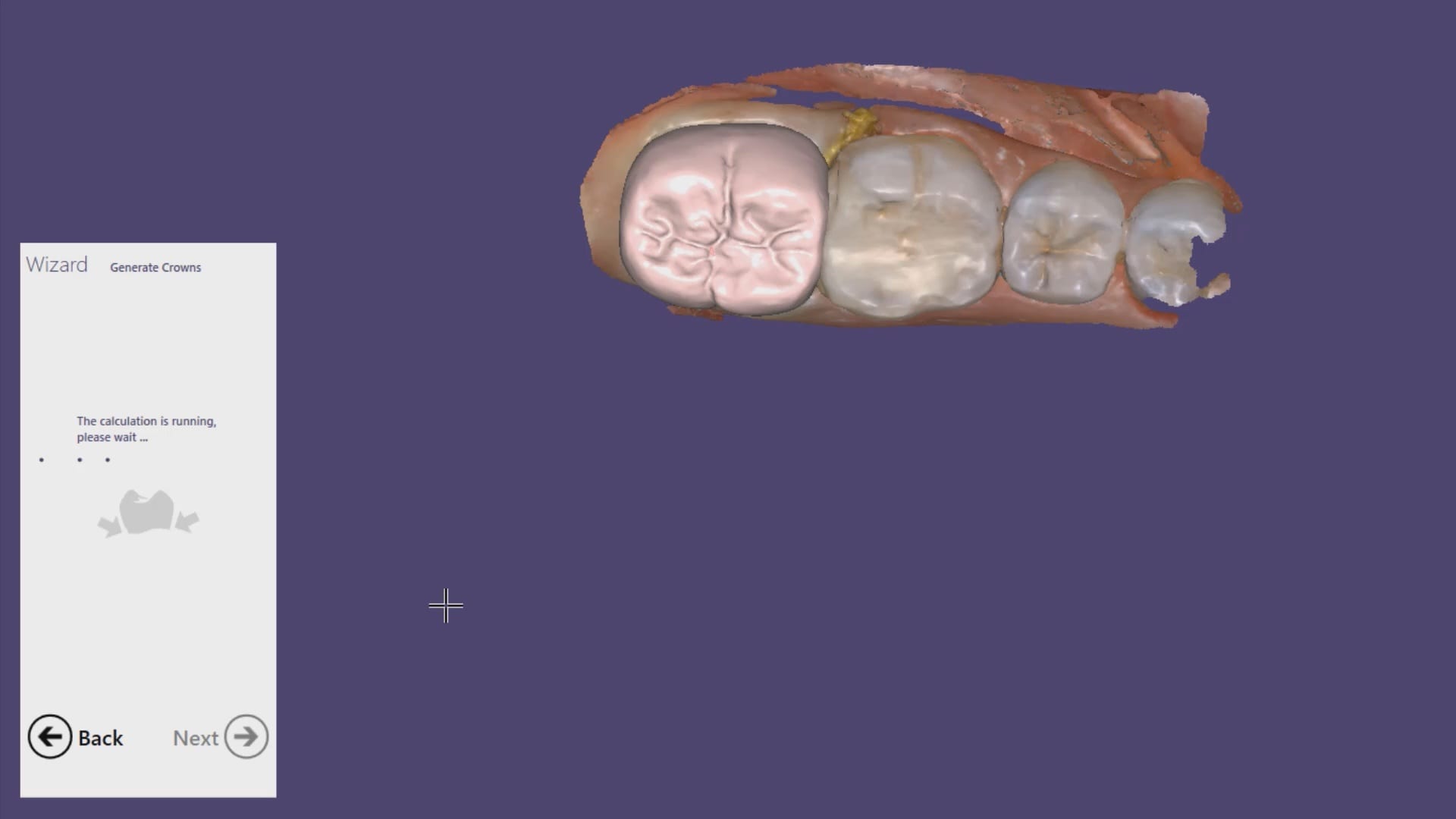
In this particular case, we are restoring a lower left molar with a full coverage crown. The pre-existing condition has multiple fracture lines and the patient currently wears a retainer. The pre-op optical impression is taken while the patient is reaching anesthesia. Once enough reduction has been achieved, the preparation is captured and an immediate proposal is rendered that replicates the pre-op condition perfectly.
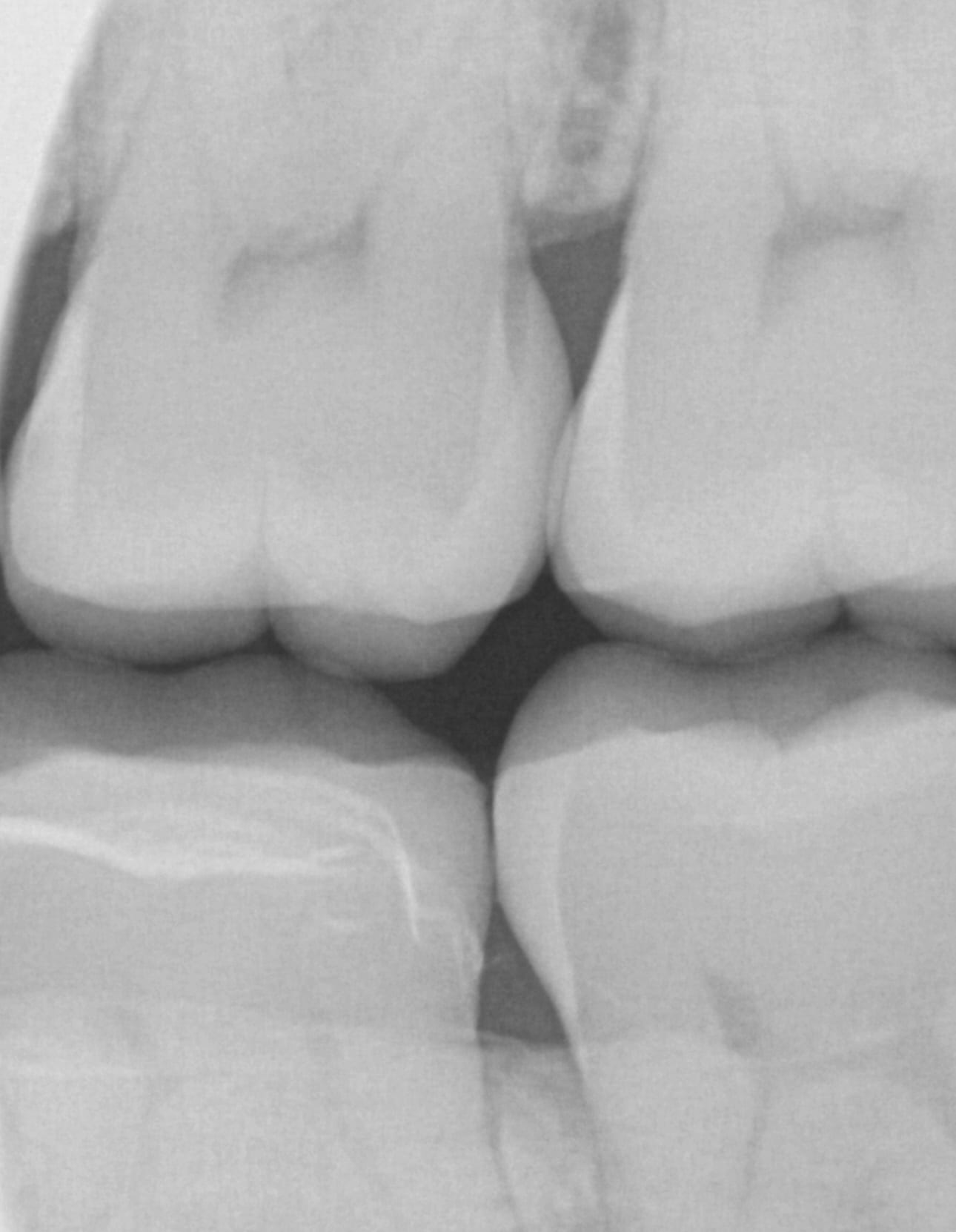
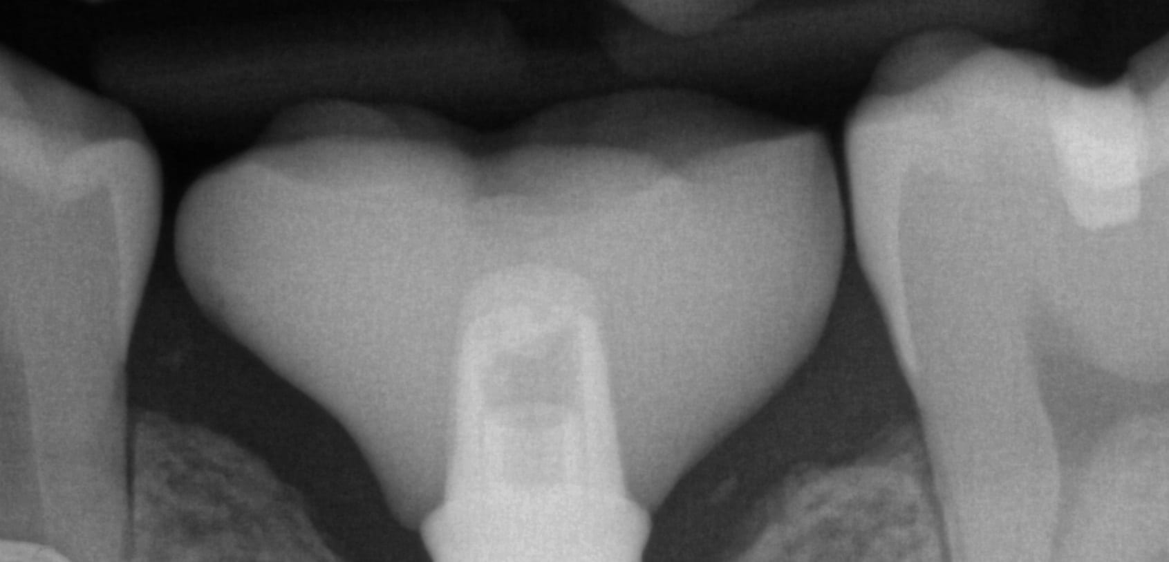
Note how the settings for the start of the adhesive gap influence the cement line that you see on the post-op bitewing after immediate delivery, even though it was milled with the CEREC MCXL.
copy mode- instant proposal

Same visit crowns can be a practice builder. We had a patient referred for in house fabrication of a restoration because she did not want to go through the procedure twice. A family member made the referral for a broken tooth.
After the tooth tested vital and the patient consented to treatment, she was anesthetized. While waiting for the onsite of anesthesia, the upper arch was imaged along with the lower arch and the bite in the occlusal one window box. The case was set up for just imaging the preparation. Most of this can be delegated to team members.
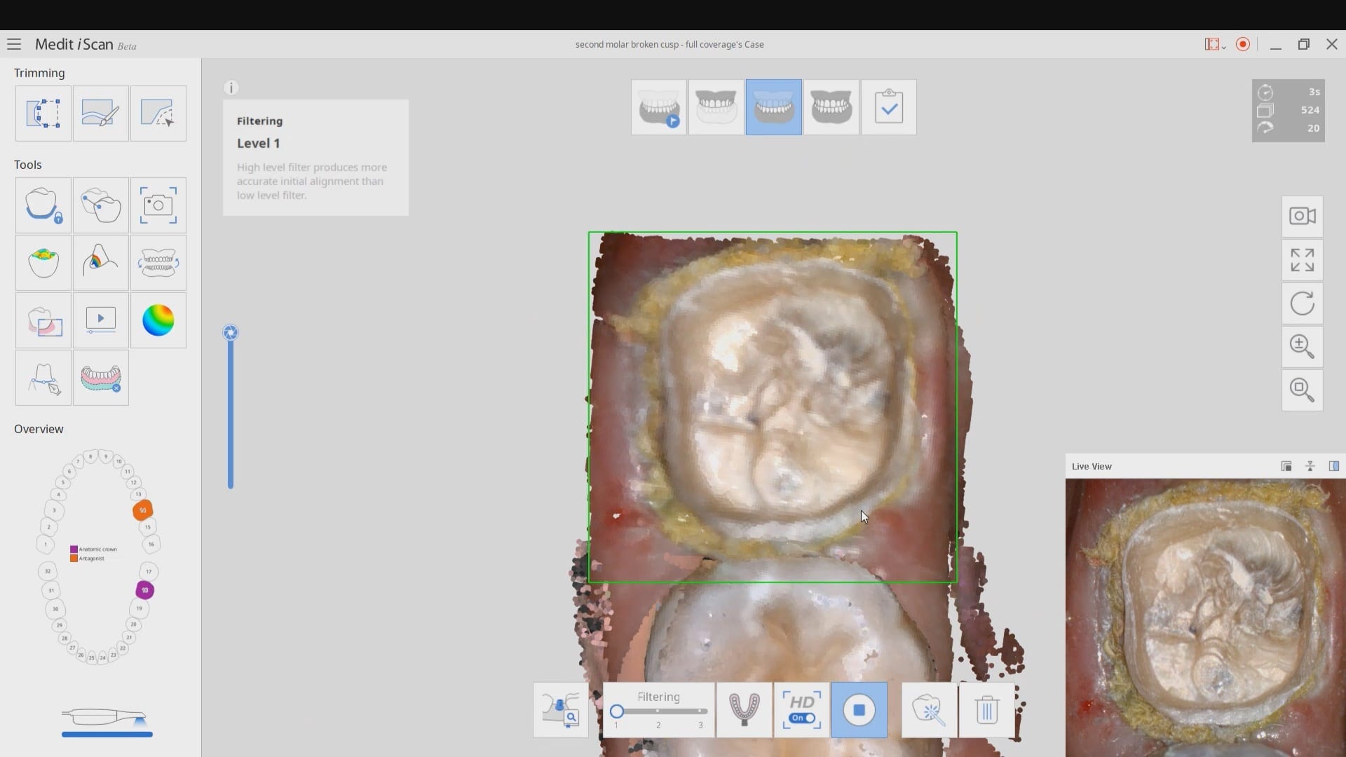
We highly recommend that you capture the final bite after you have finished preparing the most distal tooth. You can use your camera to visualize your clearance. You can keep reducing the occlusal surface until you have enough clearance.
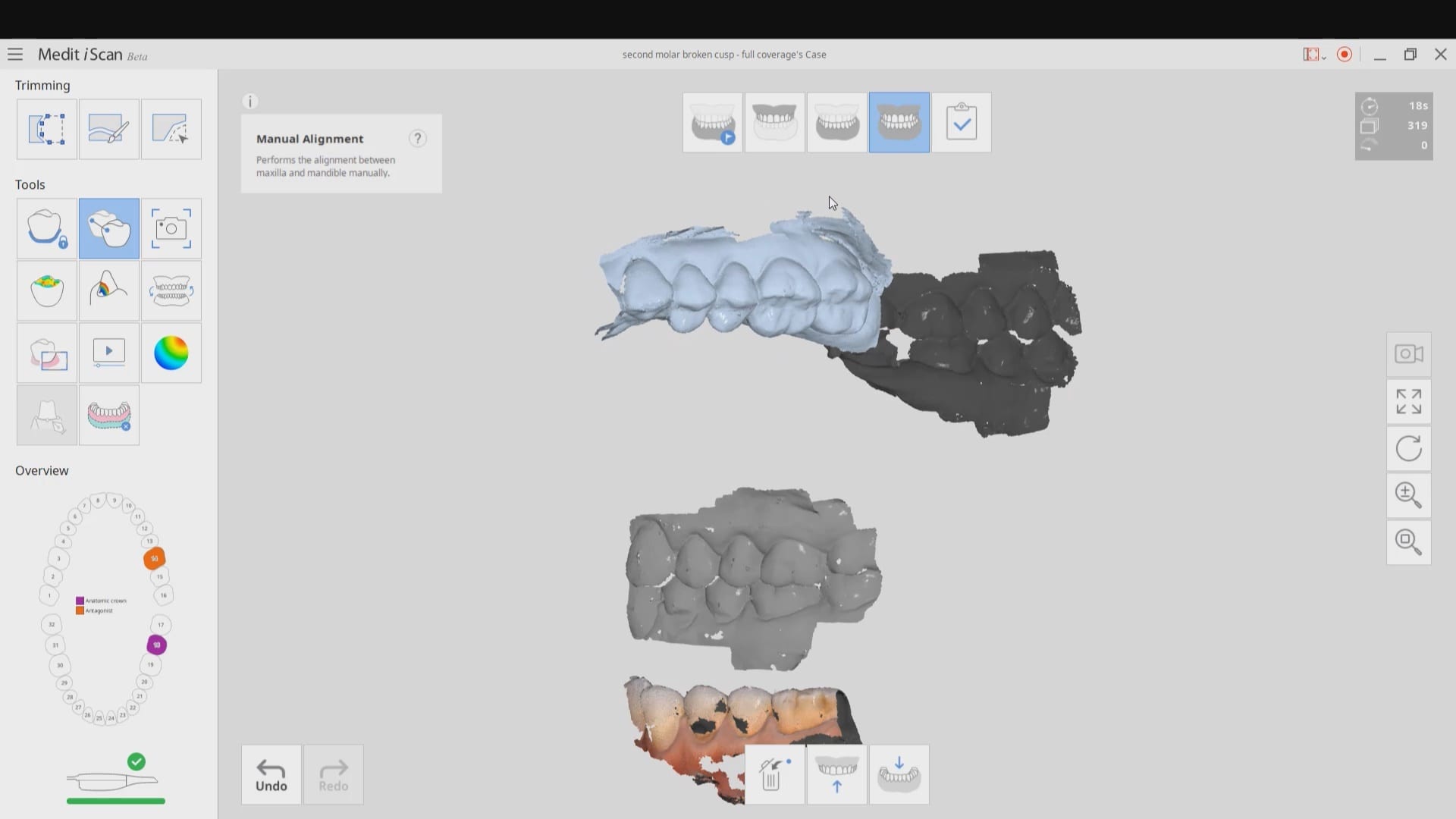
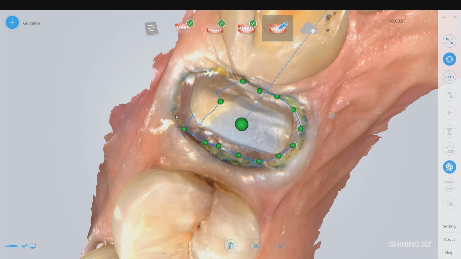
In this particular case, when we took the second occlusion images, the models would not turn green. When this happens, you should immediately ascertain if you have captured the first or second bite correctly. Double check to see if the jaw settled or if the patient moved their jaw during this acquisition step.
You can watch how we troubleshoot the bite and manually choose the second bite to relate the arches together.
Once the bite is captured, the isolite is re-inserted and the tissue is displaced and isolation is achieved. Then the predation is captured.
After the crown is seated a final bitewing is taken to verify seat and if any excess resin is left behind.

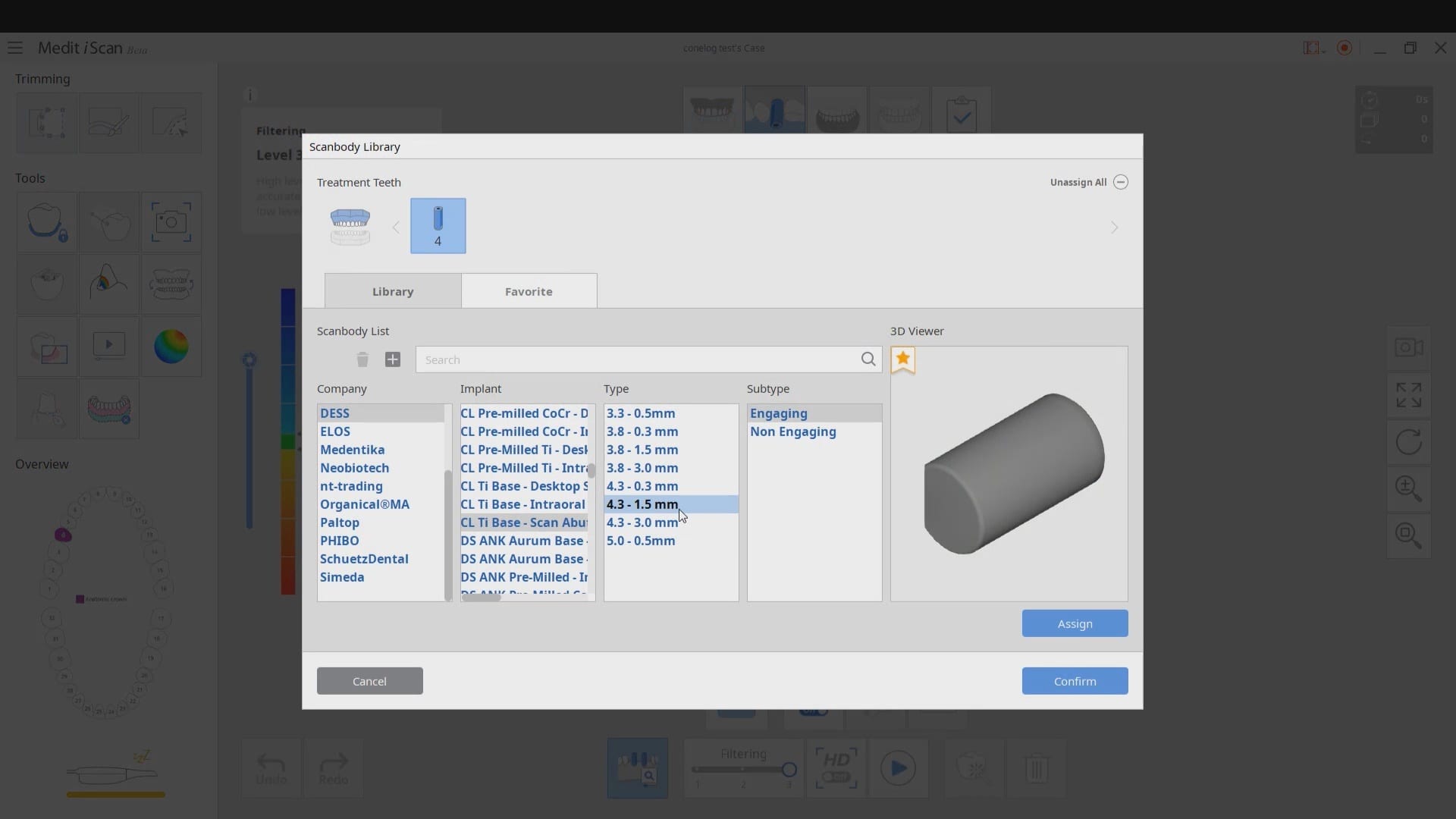
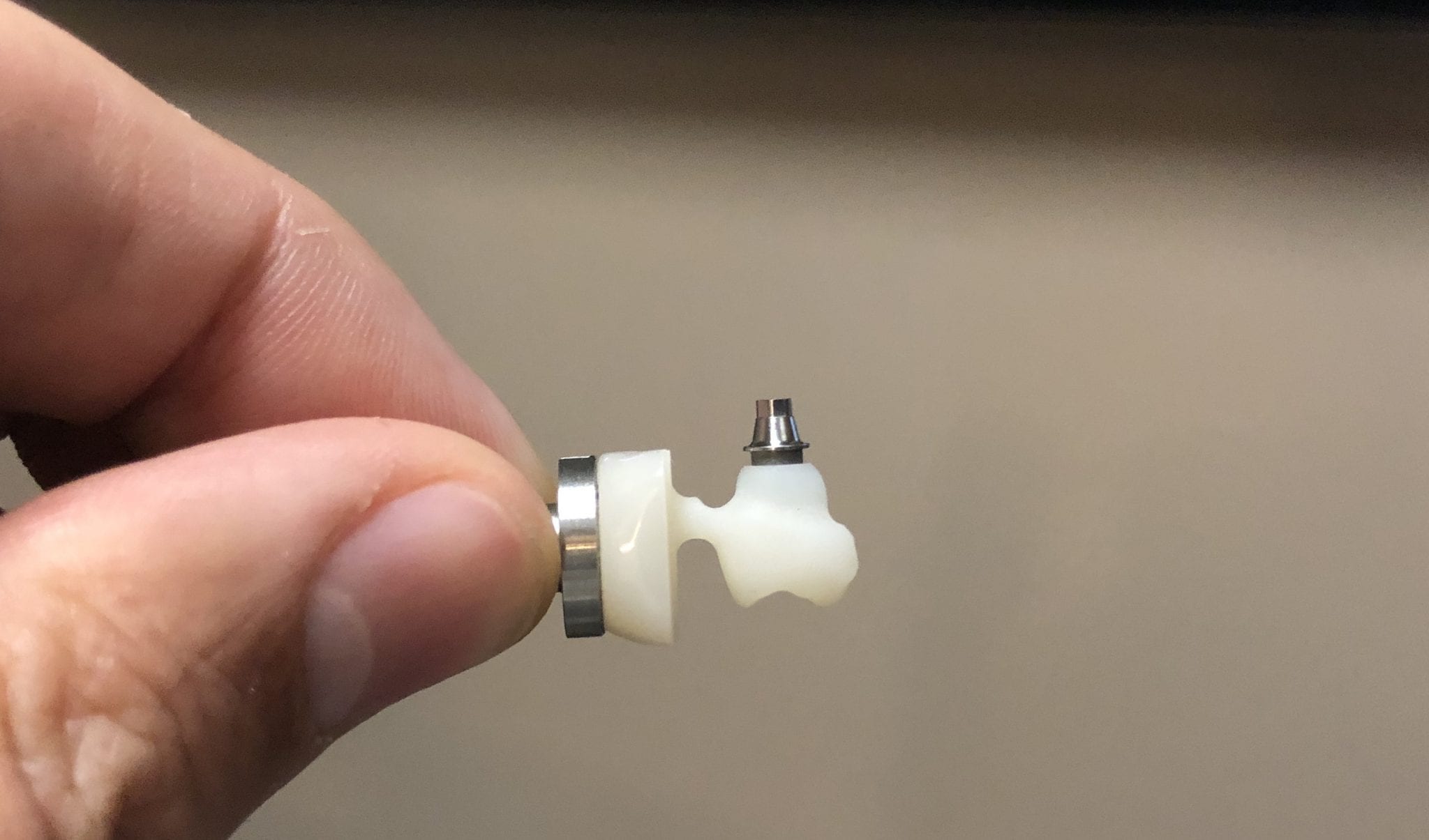
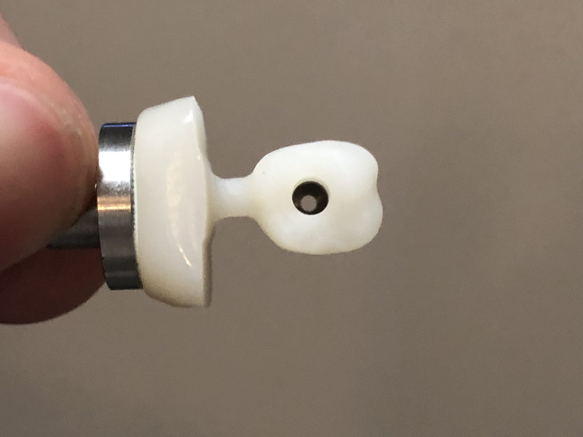
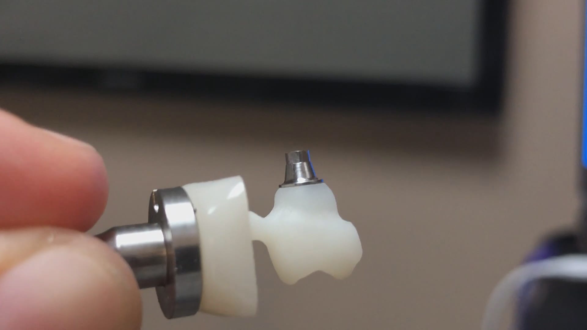
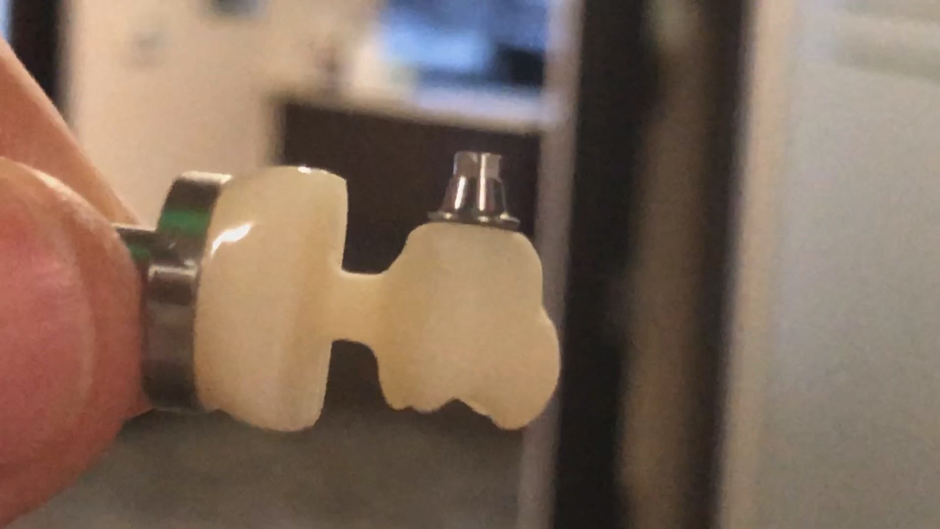
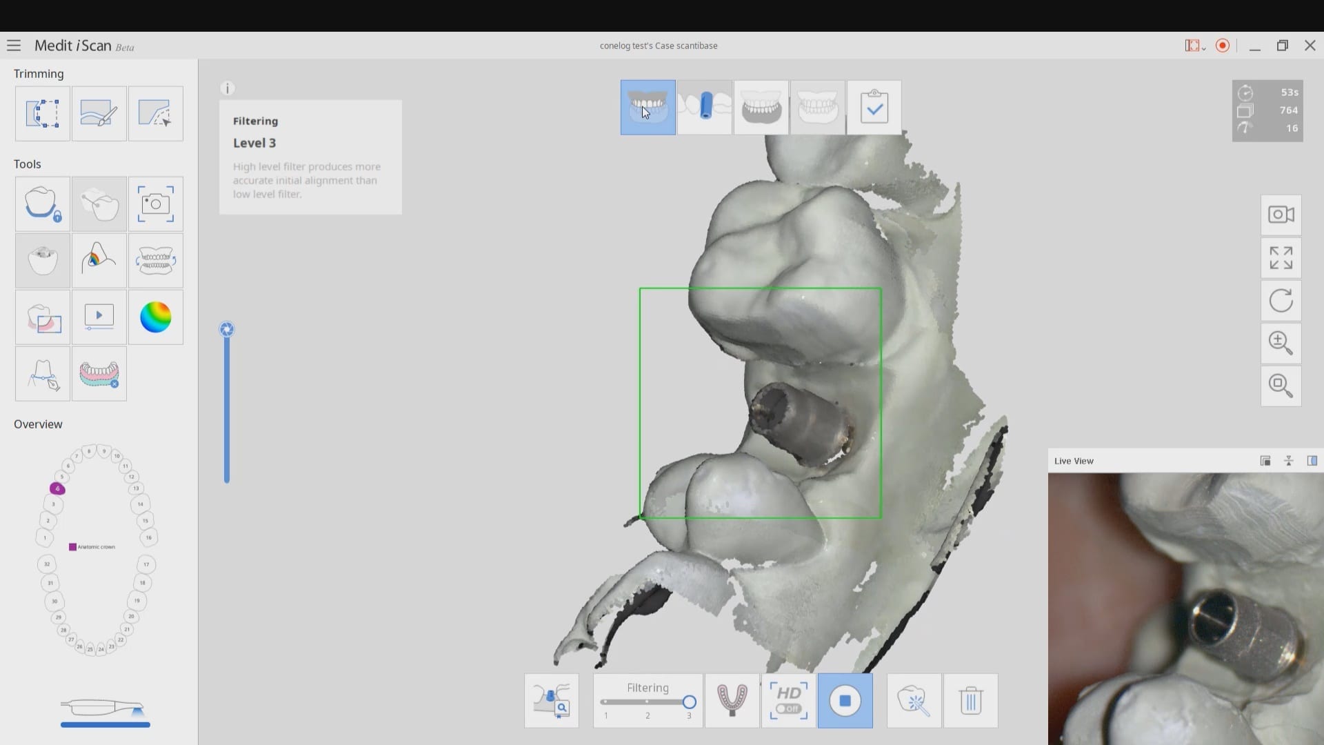
At CAD-Ray we are constantly testing milling machines that can render ceramic or metal abutment restorations. In this particular case, we are testing the conelog line of tibases and utilizing the automated identification of the scanbody with the new Medit i500 V2.1 Artificial Intelligence program. Not only does the software identify the scanbody and locate the fixture but it also imports the whole complex into the cad software where the fixture and digital tibase are already identified and aligned.
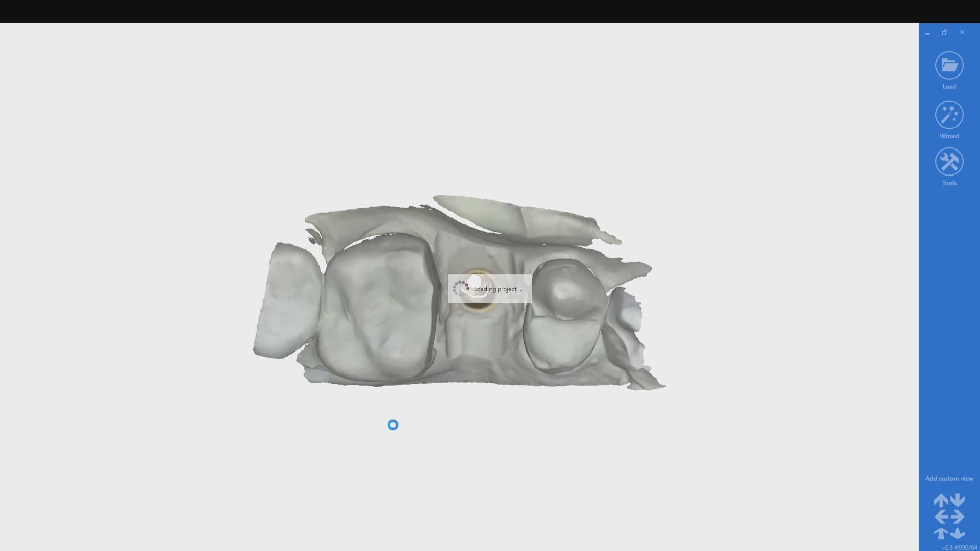
We scanned the tibase as well on the model and merged it to the digital proposal to see how closely the digital proposals matched the physical model.
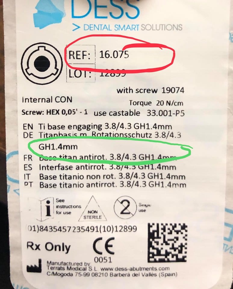

It is very important to properly identify the scanbodies and to label them accordingly. A single mis-step can result in ill fitting restorations and cause disappointment. If the nomenclature or the math doesn’t add up, it is always a good idea to contact the manufacturer of the scanbody to verify your findings.
In the first set of videos, we demonstrate how the scanbody is imaged with the Medit i500. For this particular demonstration, we placed a tibase on a conelog 4.3 mm diameter fixture and then a peek scanbody on top of it. Indexing and making sure it is seated is of paramount importance. Once the software identifies the complex it can automatically import it into exocad software so you can proceed with the design.
This test case is milled for record keeping and FDA compliance as we are distributors of multiple scanners and milling machines. We are only concerned about the fit of the restoration. After the design was completed it was then imported into milbox CAM software, nested, and the sprue was configured for the mill.
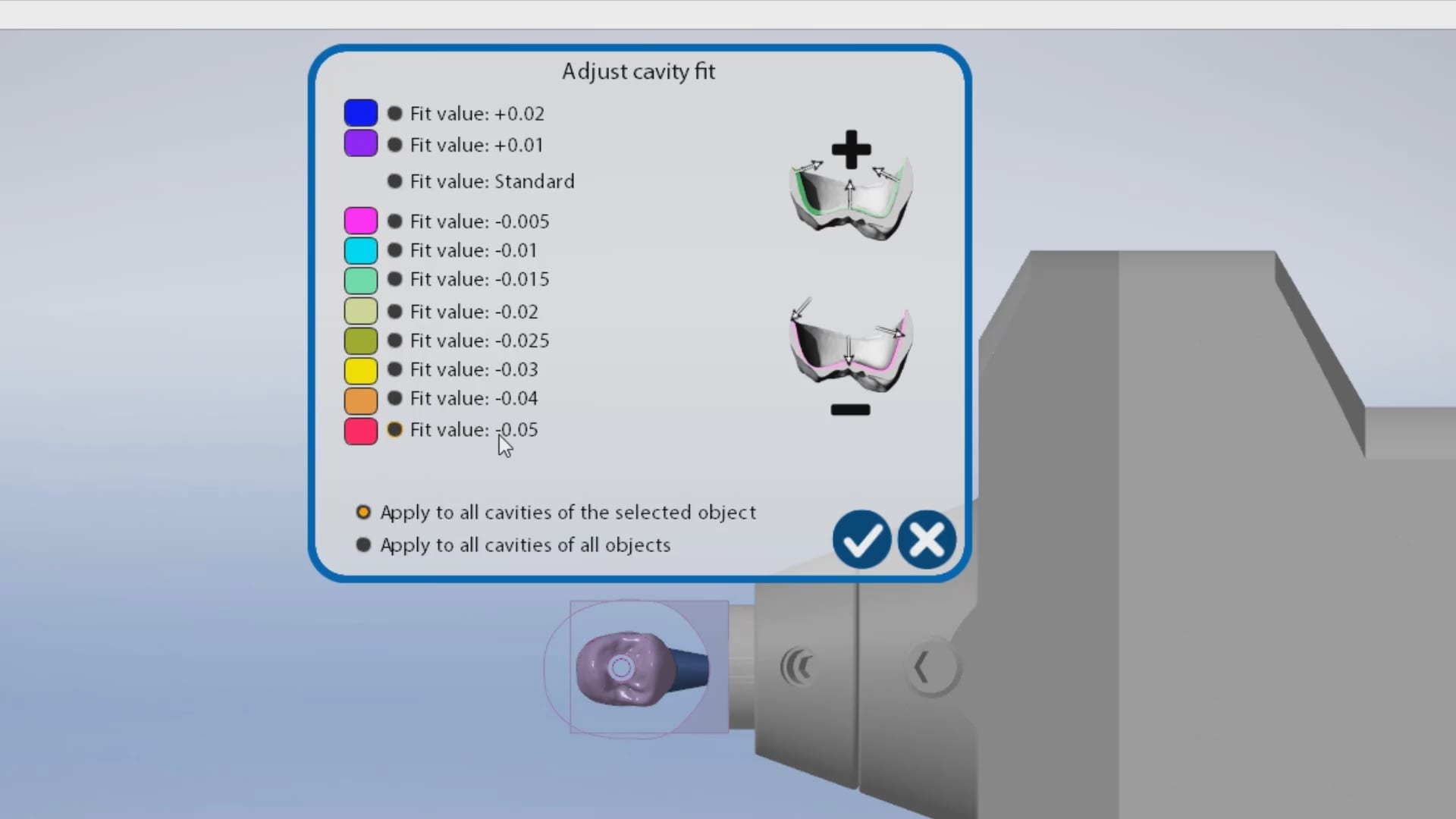
The first produced restoration did not seat completely and the internal was relieved in an analog manner. It did finally seat but by then, it lost its anti-rotation mechanism. The case was then reloaded in millbox and the internal relief was increased by – 0.05 mm. That simple adjustment allowed for proper seating without any analog adjustments. You can also appreciate some residual material that may keep you from seating. Both the software and the carbon marks left on the intaglio of the restoration can be clear indications of what needs to be adjusted.

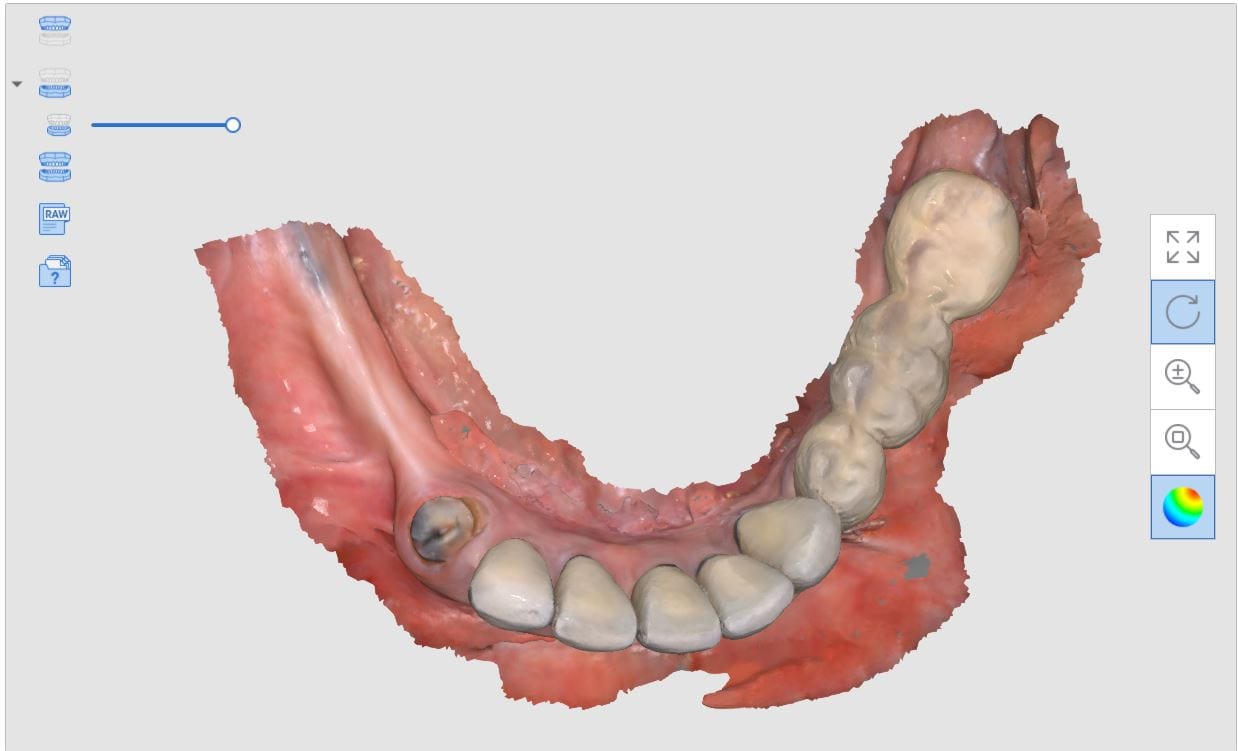
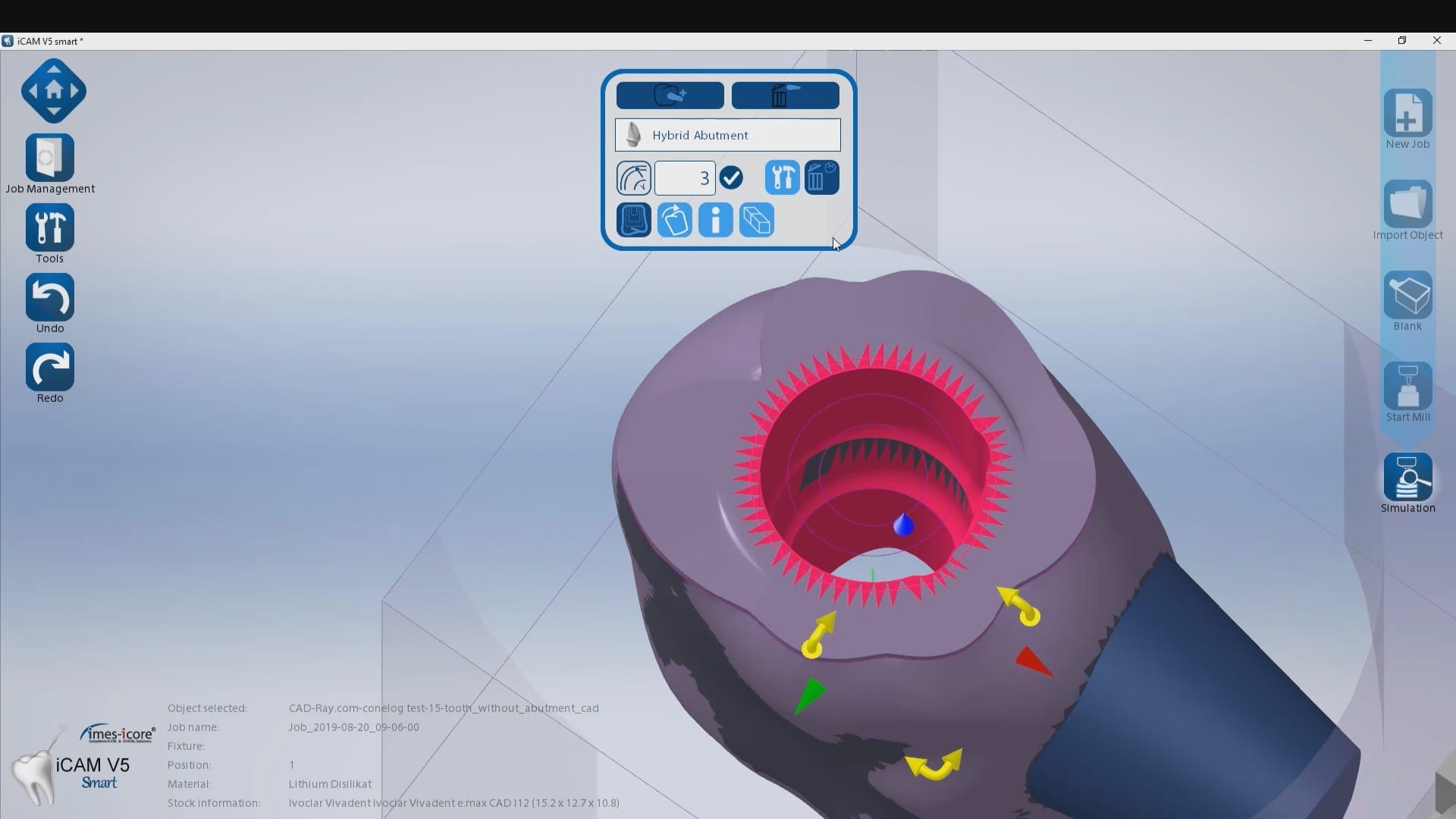
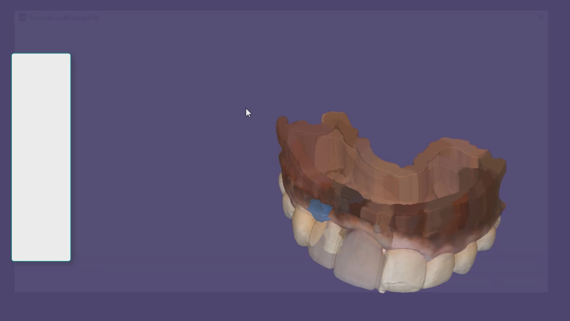
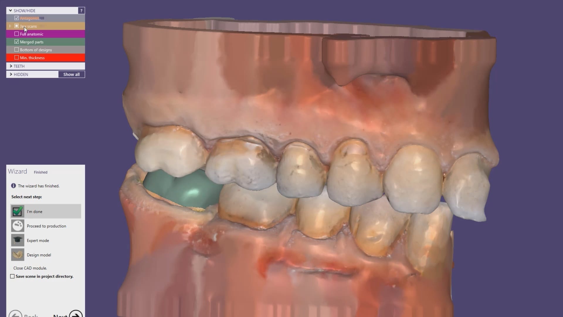
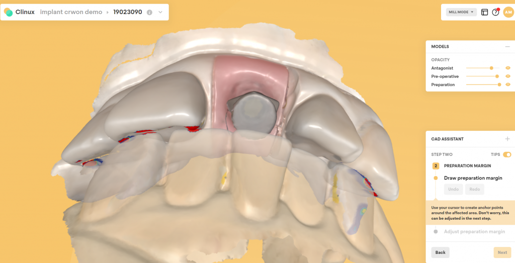
 A very common source of frustration for most dentists or those who are new to designing implant crowns is the emergence profile of the abutment or crown. Most of the time, the shape of the tissue dictates the digital design and this article showcases how we used the medit i500 for the intra-oral scan of the patient and then used exocad to design the restorations. Our advanced users can appreciate how we bring the arch model in twice- once as the maxillary model and once as the gingiva model. We then digital sculpt the tissue to create the proper profile yet we still have the original model to reflect back to asses the changes.
Download to ImplantCrownShaping.ZIP to design along
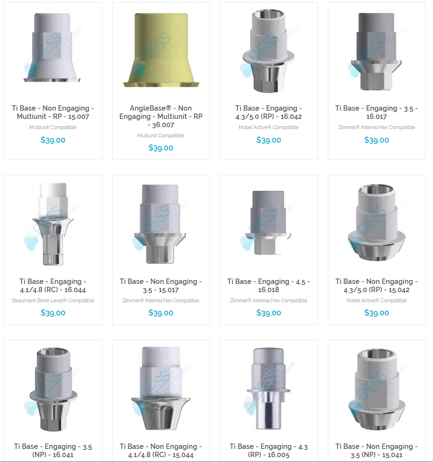
DESS Library Information for Nobe Active Compatible Components
NobelActiveCompatibleComponents-DESSUSA2019-2NobelActiveCompatibleComponents-DESSUSA2019-2

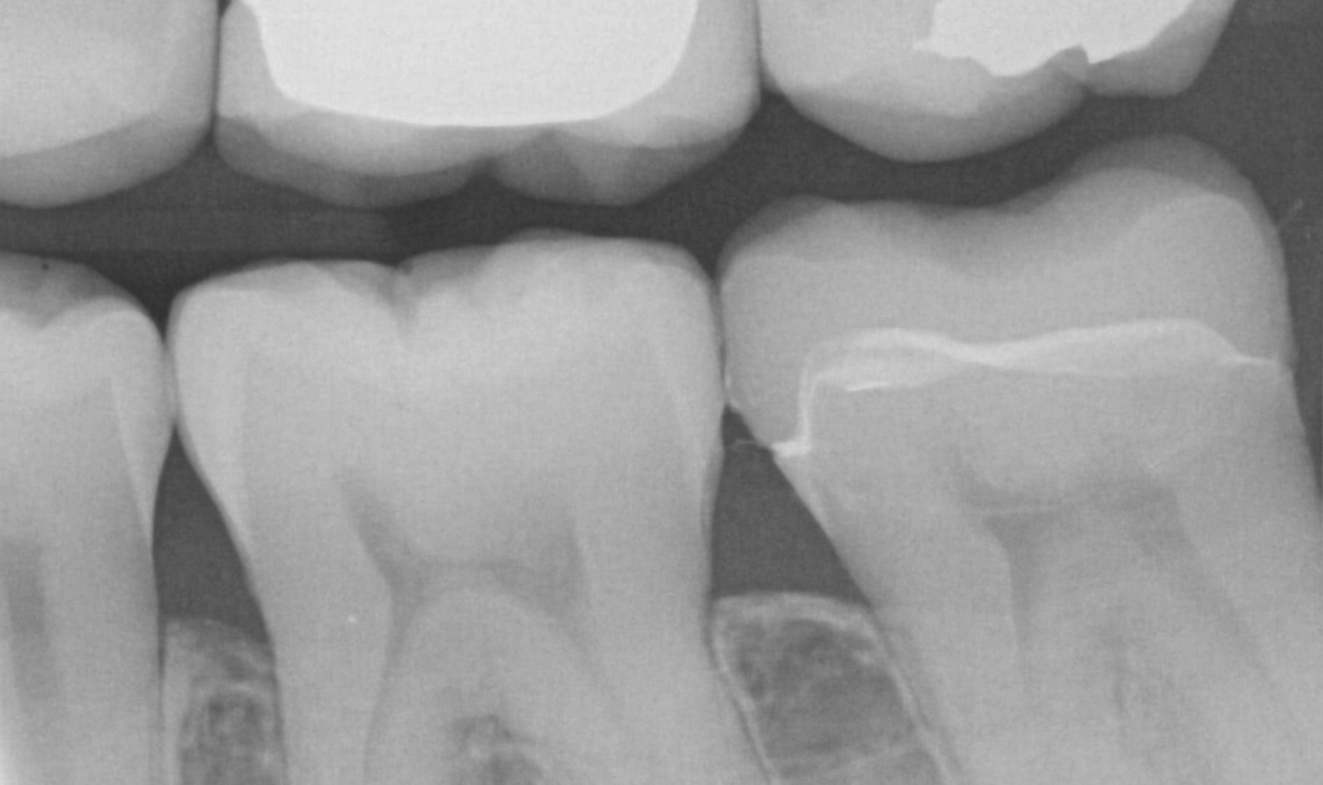
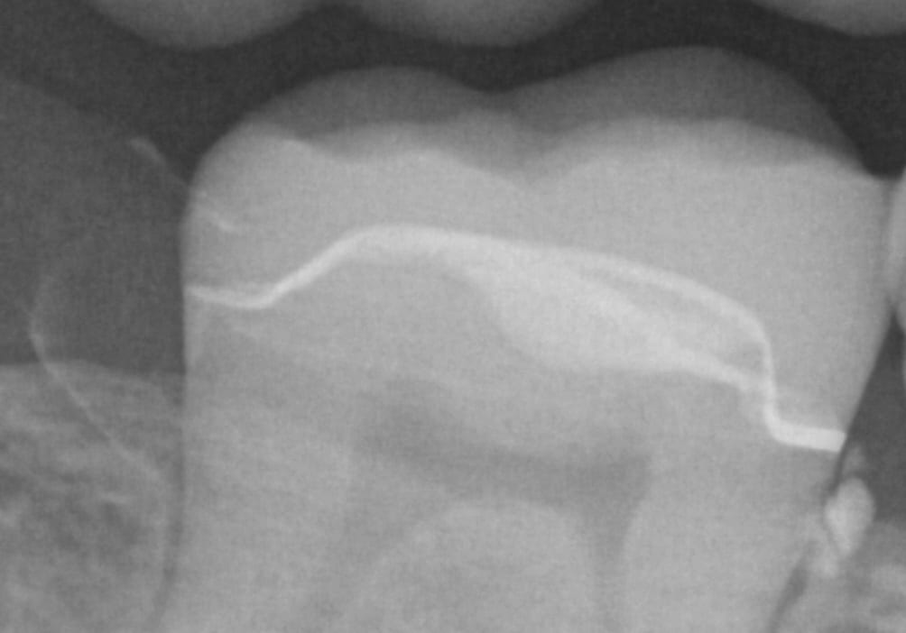
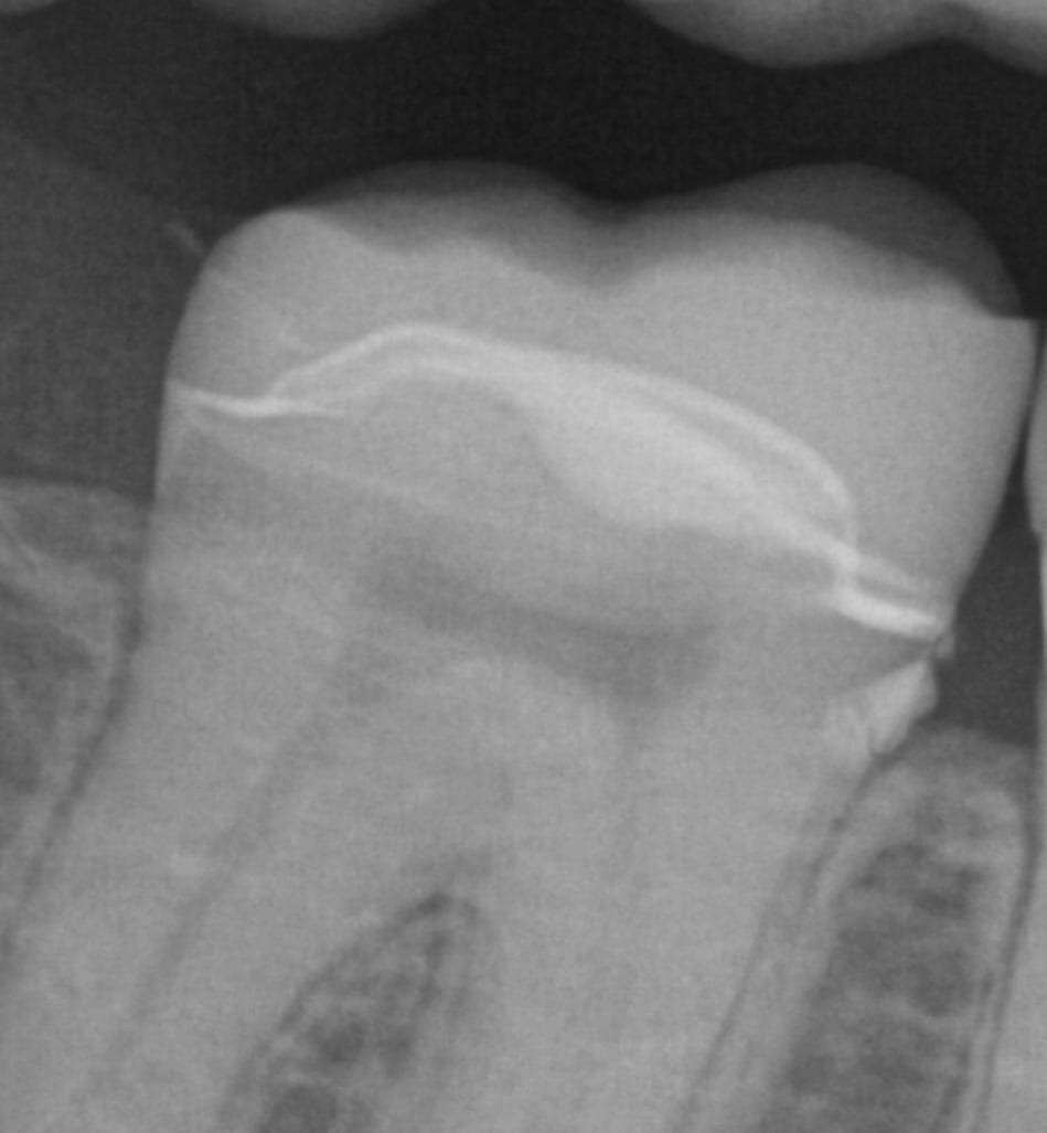
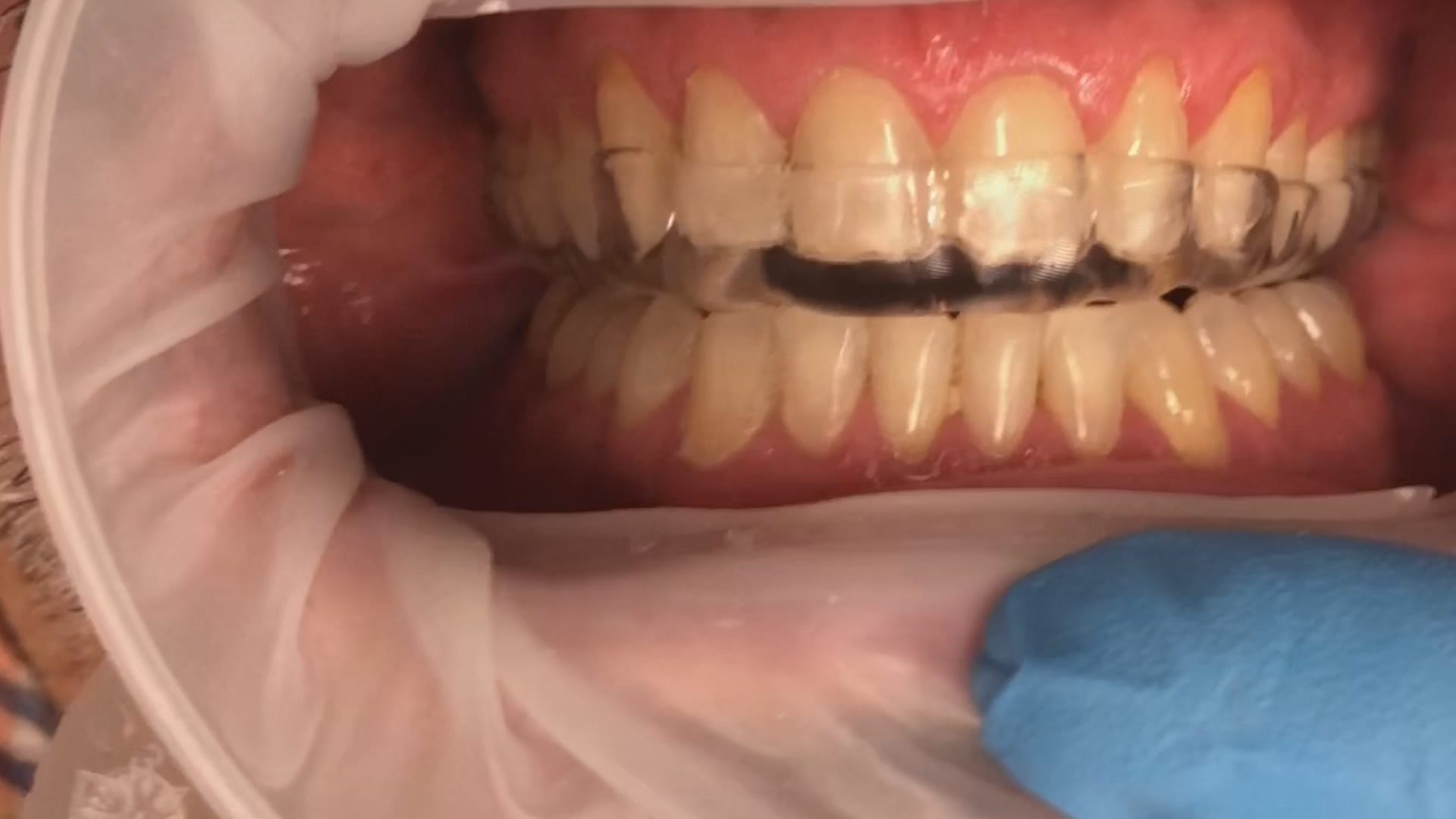
Few things in dentistry that can be as frustrating as seating a second molar restoration, whether you are doing same day dentistry or having a lab made prosthesis delivered. Here is a protocol we recommend that you follow to dramatically reduce surprises and post op adjustments. In this particular clinical case a zirconia crown debonded and we elected to fabricate an in-office emax restoration. The sequence is as follows:
Immediate post op x-rays were taken to verify seat and aid in resin cement removal. The excess cement was removed after the x-rays were taken

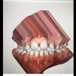
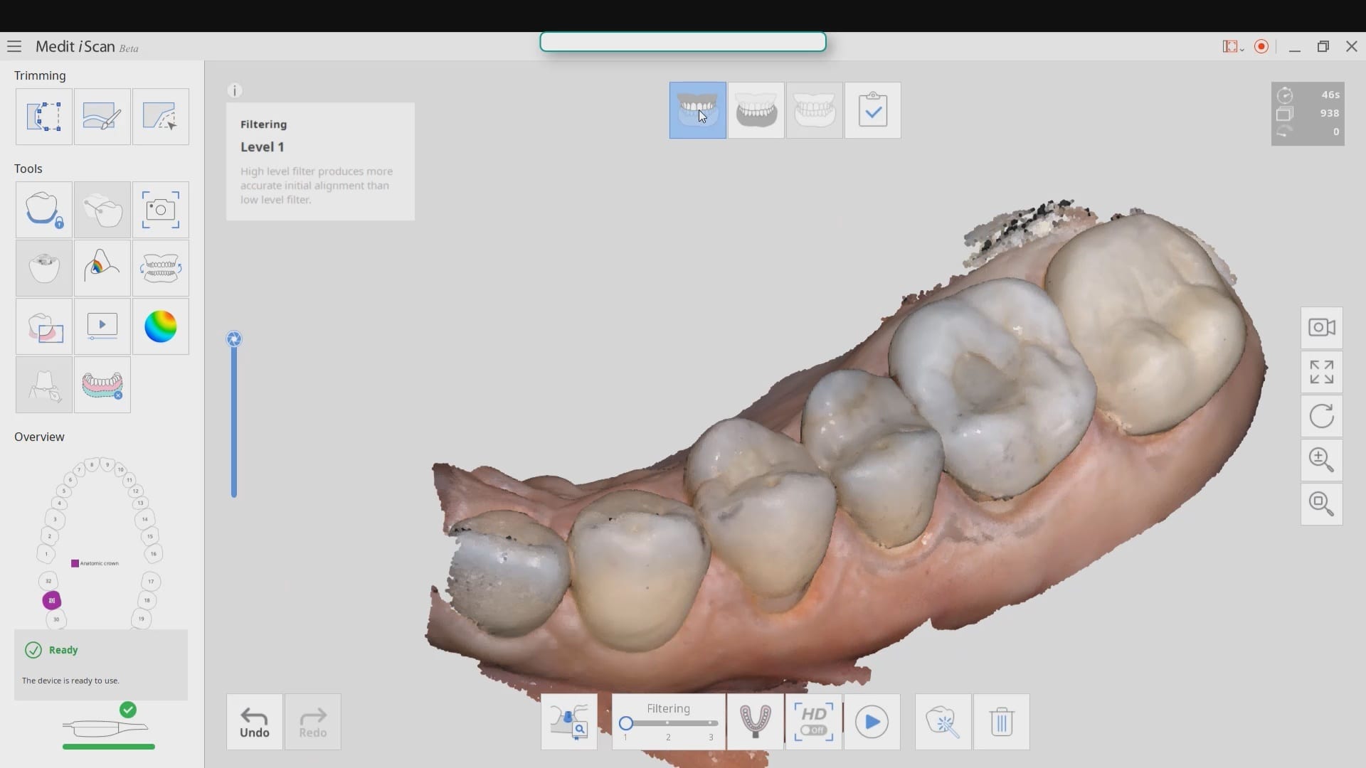
A common request when processing models is to create a plan that matches the occlusal plane of the arches. To keep it simple the algorithms of the Medit iScan will create a plane from the lowest data point on one side of the model to the highest point on the model on the contralateral side. You can control this plane by using the edit tool in the arches and crop out data so that you help the software to find this plane more easily. The more discrepancy there is between these data points will render drastically different planes than the occlusal scheme as seen in the attached photo. Besides, the less data you have to process, the faster the models will be rendered.

We got a bat signal from a group of doctors who were having trouble with ill fitting restorations to tibases. This can suck up a lot of time and energy to pinpoint the exact source of the issue, and you basically have to go through a pilot’s checklist before take off. Here’s a list you can use for yourself to determine what the cause of the issue, after you understand what the issue really is.
We took the case file from our users and directly imported their design case into a few of the CAM systems we have at CAD-Ray. We used Celtra Duo burner blocks to verify the fit. The screw-mentable restorations were binding on the walls of the tibase so it took a few adjustments to seat it completely. The good part is that the carbon on the titanium abutment leaves metal marks on the internal intaglio, so it is easy to know where to adjust
The restoration still needed some adjustments so we played around with some of the spacer settings, screw access holes, and other parameters to get it to seat all the way.
Even with these adjustments of the parameters a little analog milling helped get the restoration seated. The CAM software can give you plenty of hints on where it will bind. We recommend that you don’t change your spacer settings and understand that you will likely bind on the walls of the tibase and/or restorations as it is difficult for any machine to mill out all the detail you need to have NO adjustments. The good news is that the indexing and anti-rotation mechanism work properly.
In conclusion, it is physically impossible to mill the intaglio of a ceramic restoration to perfectly retrofit most tibases as they have too much detail that even 5 axis milling machines cannot reach. The choices are to increase the space between the walls of the tibase and the restoration providing enough relief to allow you to seat the restoration, but that comes at the risk of losing your antirotation mechanism. Alternatively you can mill them out knowing full well that they will bind and using the sophisticated CAM to pinpoint the areas that need adjustment.

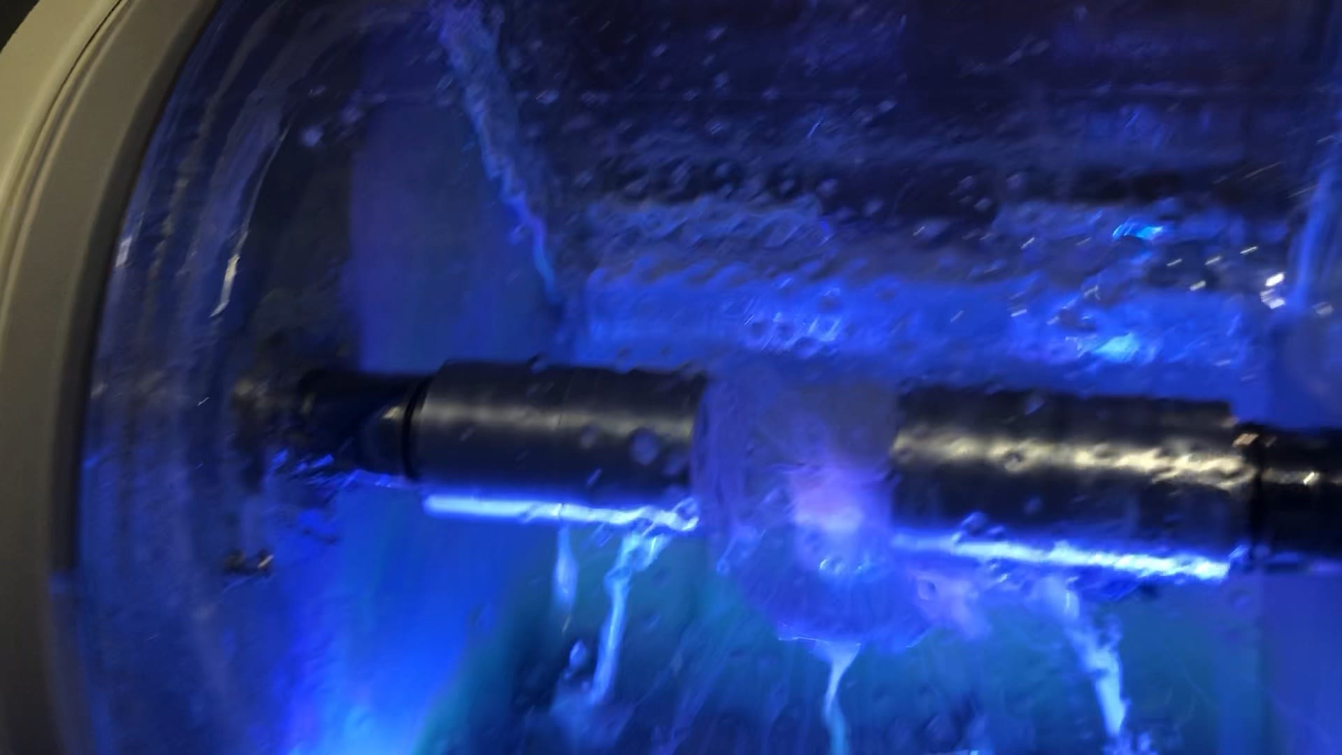
With the Meditlink software you can design a case and then export the designs and take them to any milling machine of your choice. In this demonstration, we use the CORiTEC ONE to mill out the metal abutment in 45 minutes. This procedure is not intended to be a single appointment visit so timing is not critical and you don’t place undue wear and tear on the milling machine.
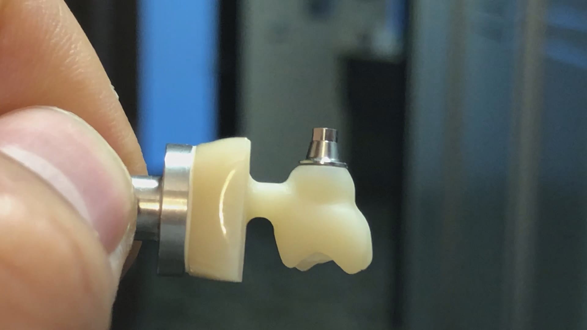
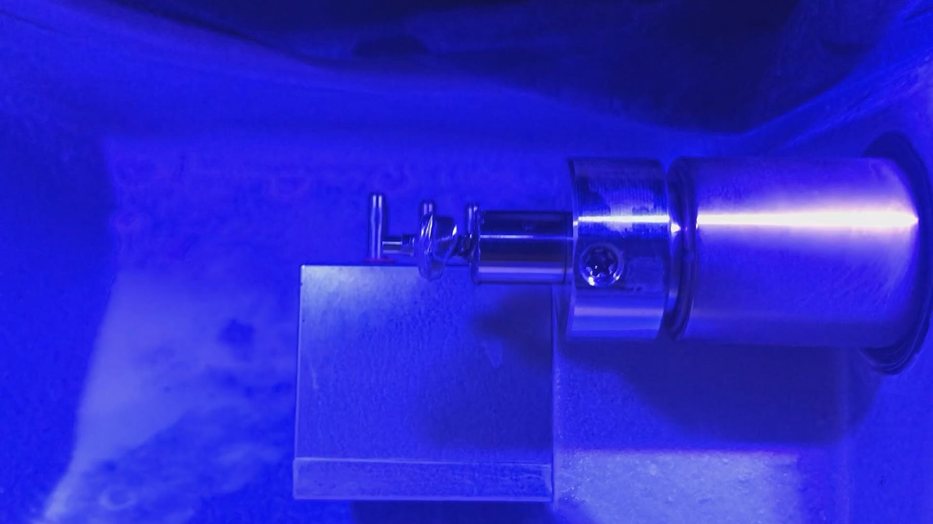
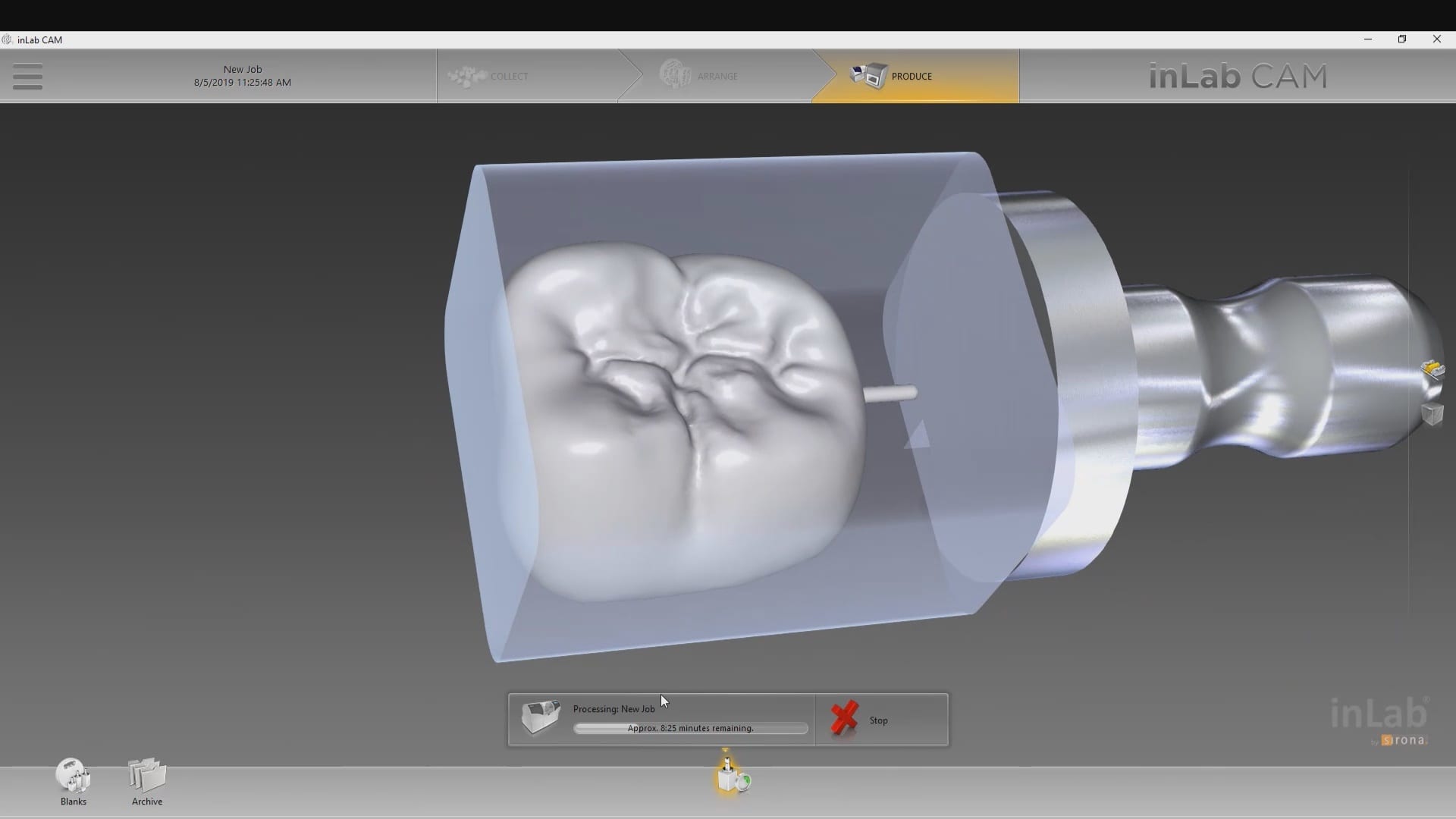
The crowns were milled with two different milling machines. A Celtra Duo block was used and milled with the CEREC MCXL and retrofitted to the abutment to verify the fit and accuracy. The same crown stl was milled out of Vita material in the imes icore machine. The whole point of the demonstration is that you can take scans from any intra-oral scan, take it to CAD software (in this case exocad) and then export the case and take it to any printer or milling machine of your choice. You must make sure critical information is accurately transferred from your CAD software to your CAM software, which is generally the construction / project file that accompanies the STL files of the prosthetic components


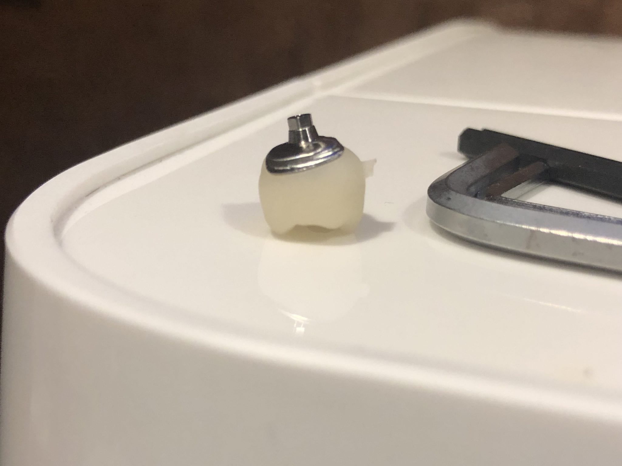
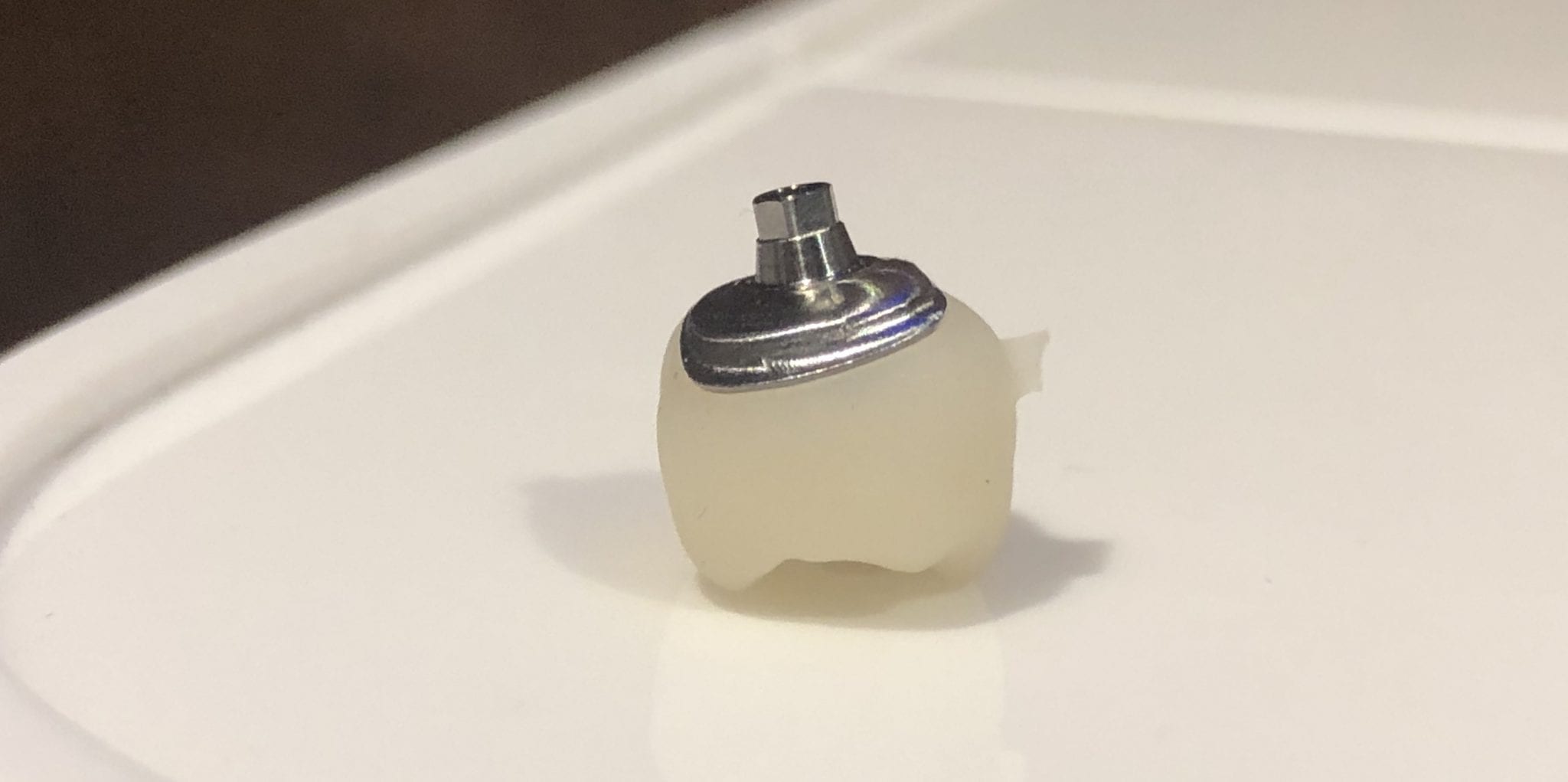
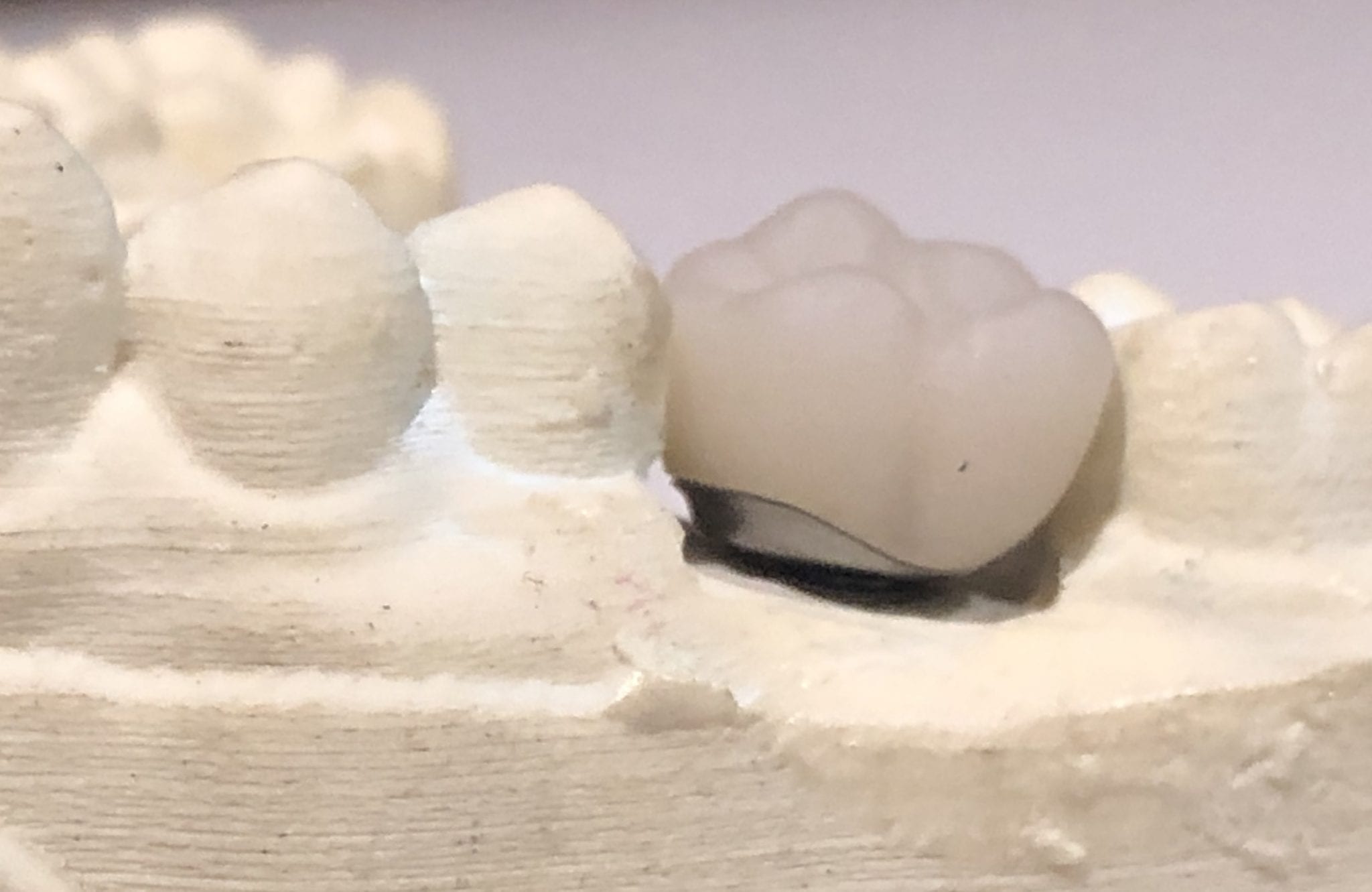
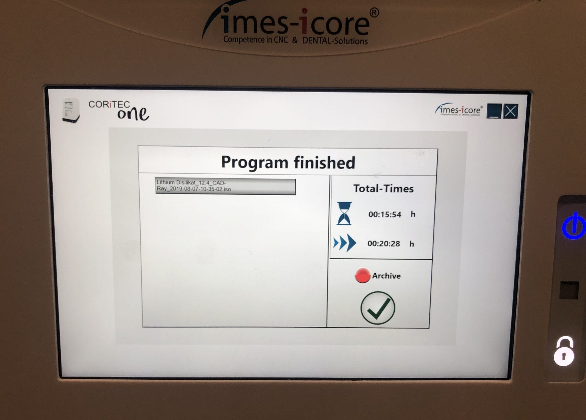
The same crown was milled out of Vita’s Suprinity material in 20 minutes with the imes-icore CORiTEC ONE. Take note of the internal adaptation of the metal abutment and the restoration and how when it is flipped upside down, the restoration does not fall out easily!

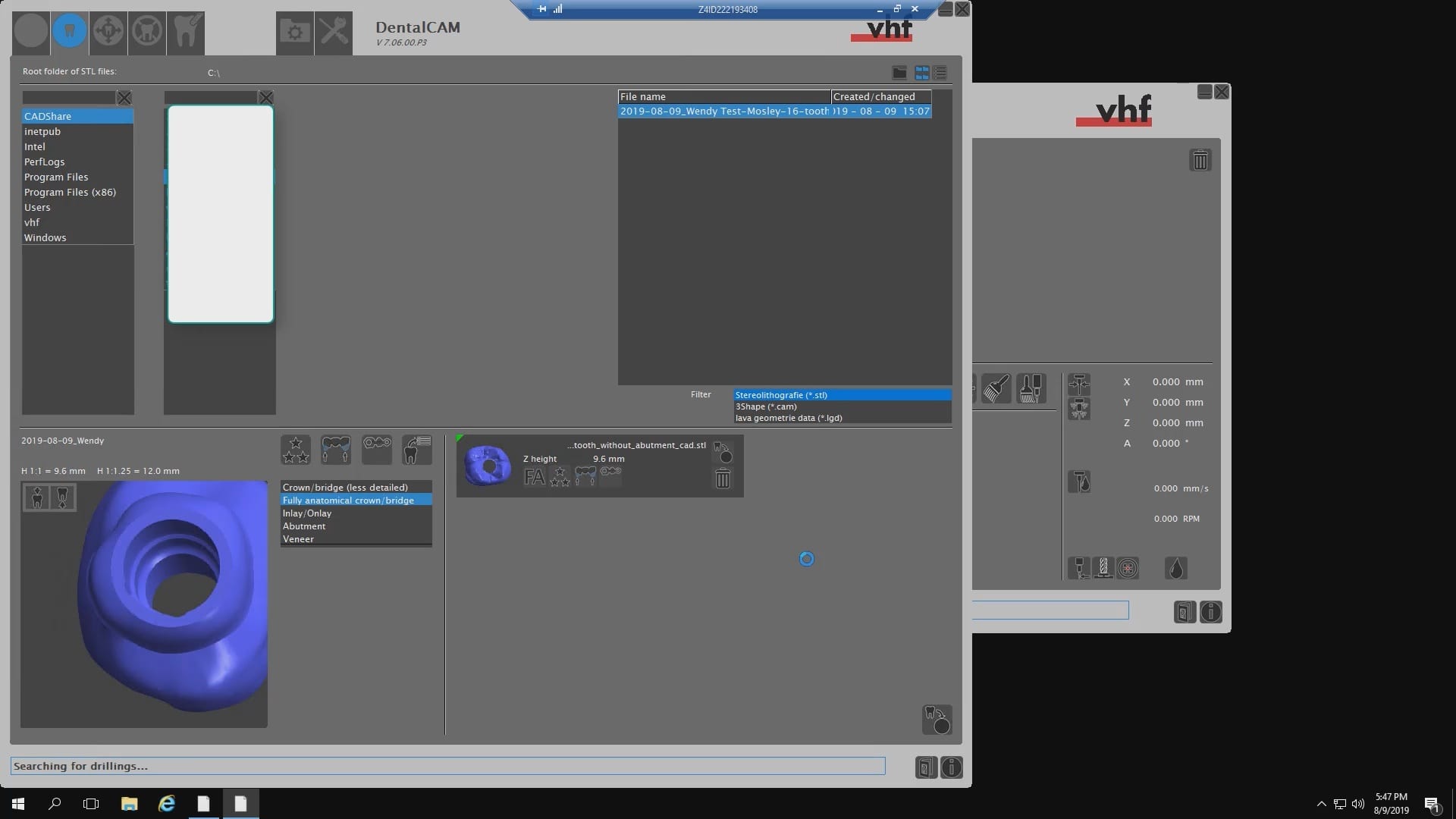
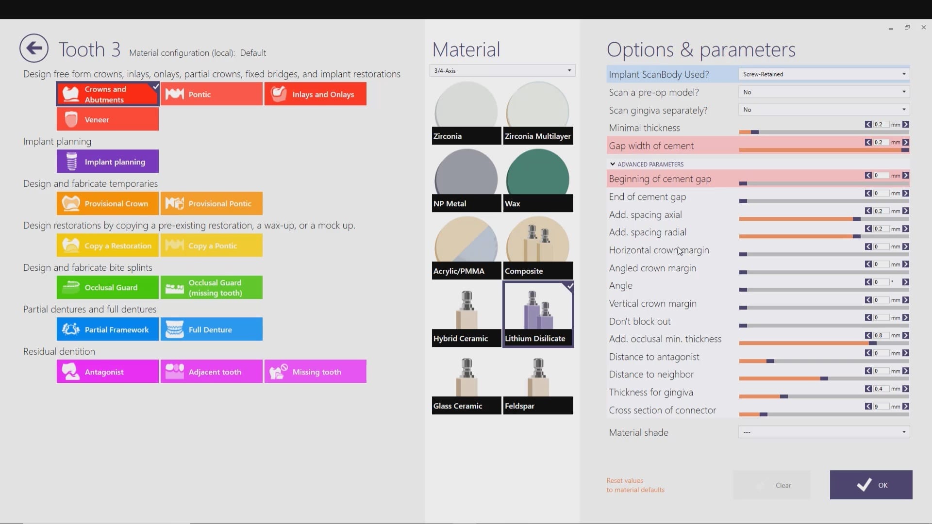
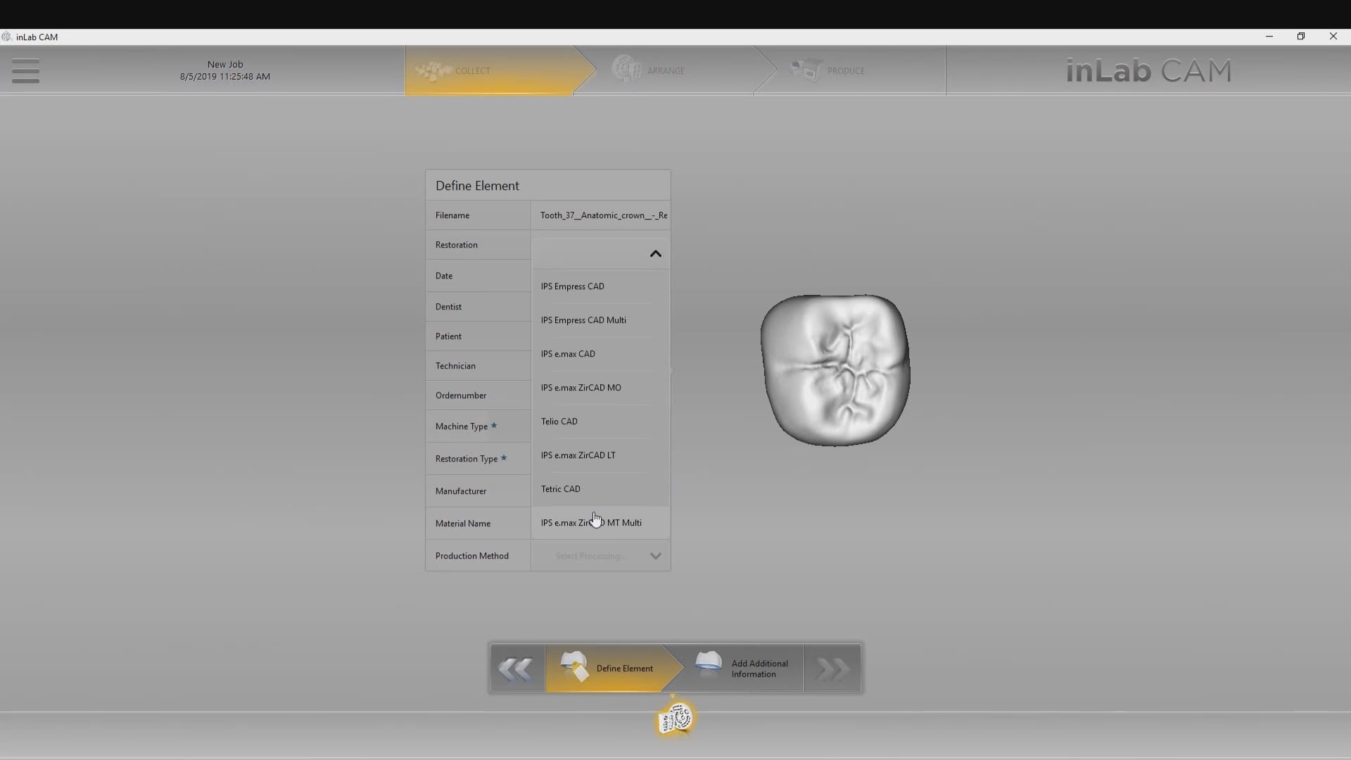
When imaging and designing a restoration in exocad, with models captured by the Medit i500 intra-oral scanner, you will produce an stl file of the restoration along with the construction file.
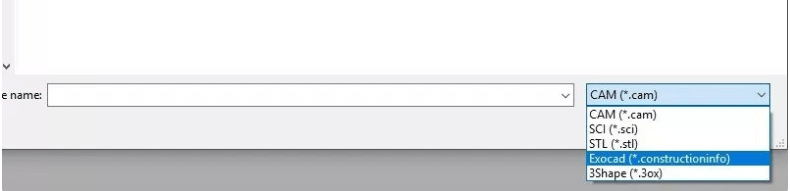
The stl file alone carries enough information for most CAM software to instantly mill the restoration. The CEREC cam software gives you the ability to either import the project file or the stl file.
In this demonstration we showcase how you have to redraw the margins in the CEREC inlab software so you can mill the restoration when you only import the stl file.
Alternatively, if you imported the construction file, you could have skipped the margination step.
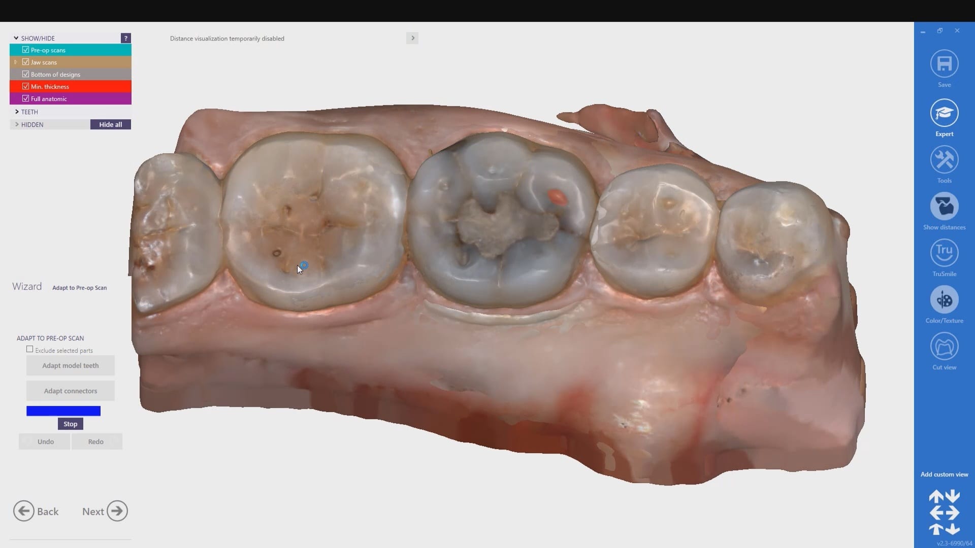
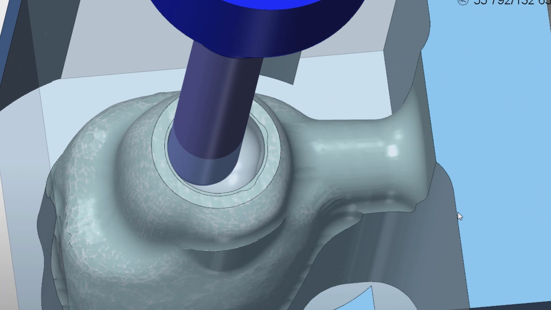
Our advanced users can appreciate “the lip” at the margin of the restoration. This is a function of the minimum parameter thickness in exocad.
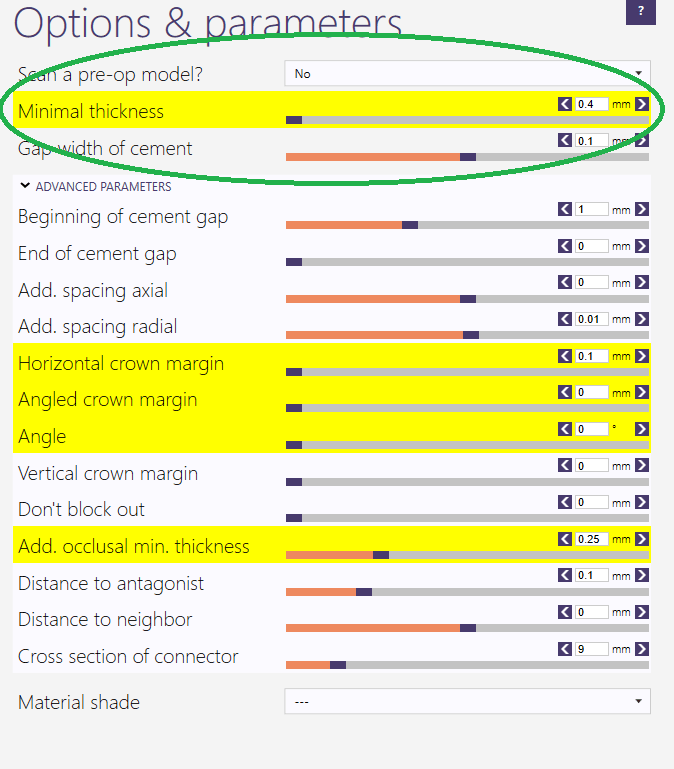
Most people set this setting to 0.4 mm or less which adds material to the margins so they are protected during the milling process. This thickness is invisible to the naked eye and produce desirable results with lithium dissilicate


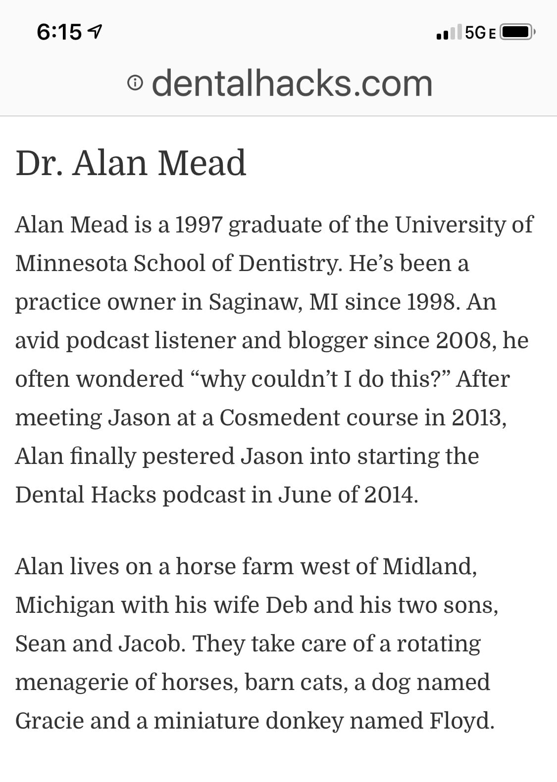
We’re so stoked to hear this podcast from Dr Alan Mead of Dental Hacks fame on CAD-Ray.com and the Medit i500
Here’s the link

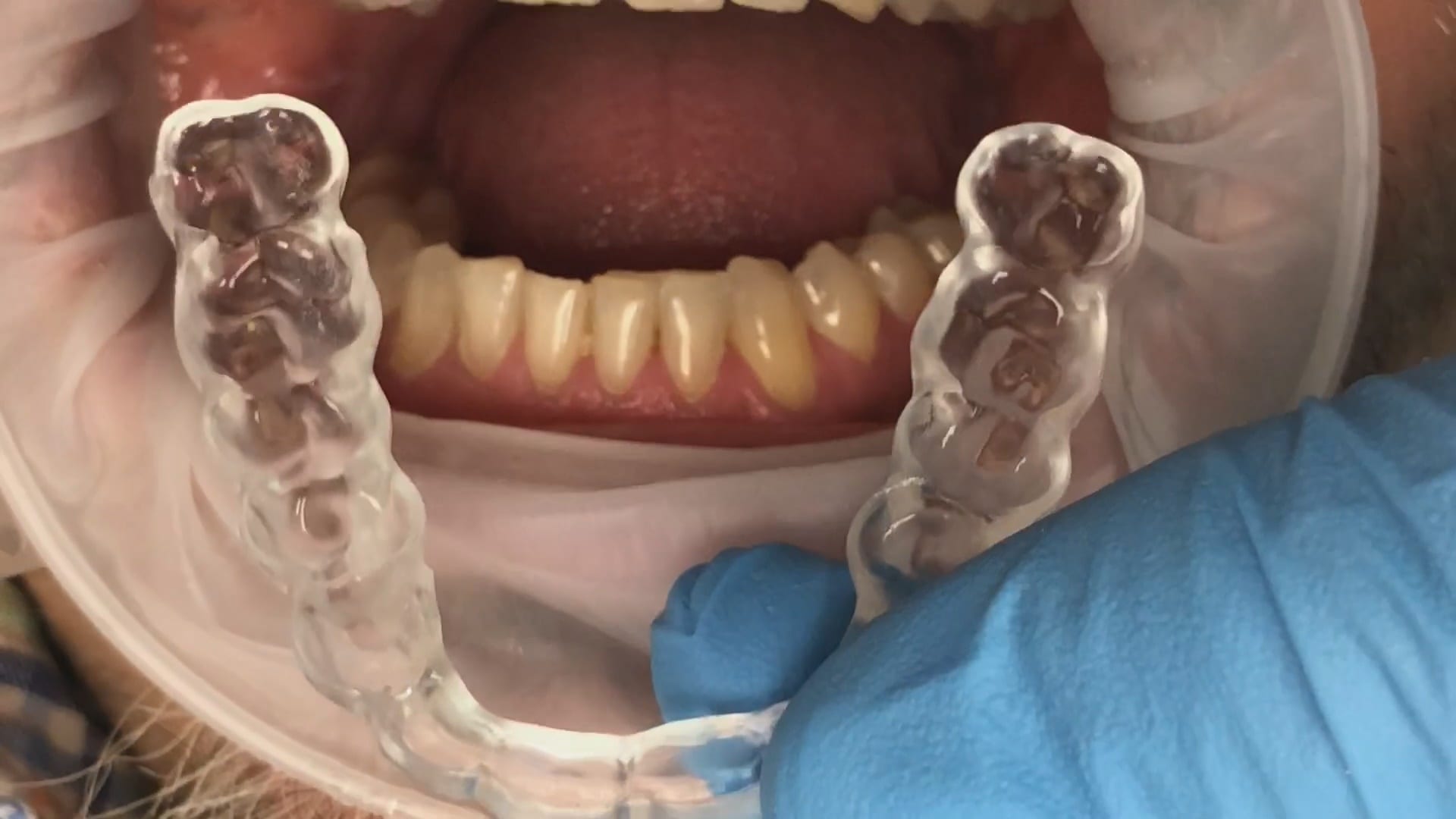
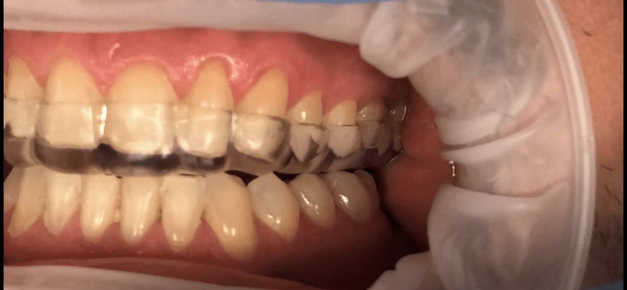
This is the occlusal appliance that was milled and delivered from this patient’s scan approximately 7 days ago. The appliance did not need a single adjustment neither on the occlusal surface, nor in the intaglio.
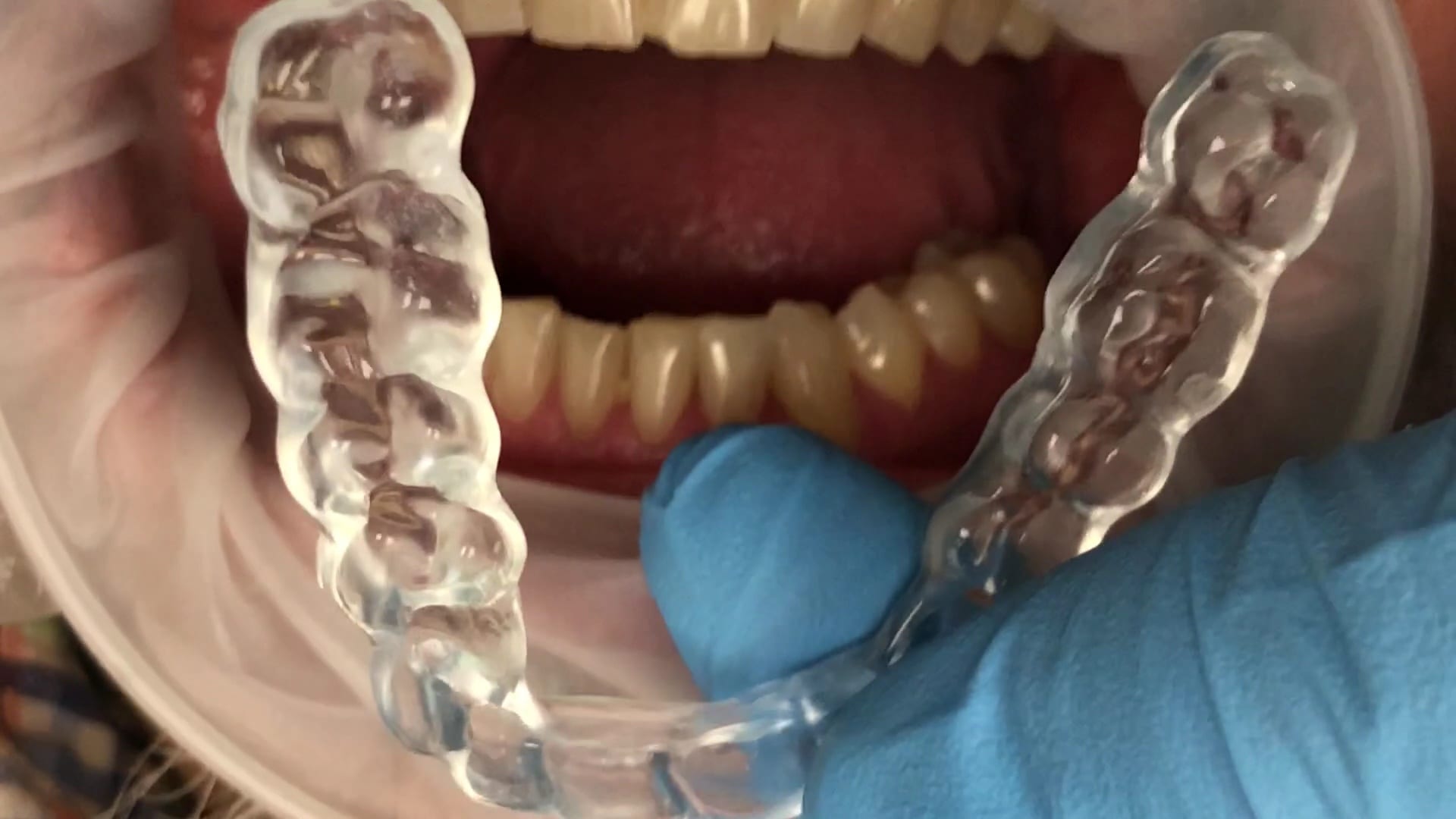

One of the biggest challenges of capturing a bite for an occlusal appliance is to properly tripod the upper arch to the lower arch. With PVS impressions we just send the impressions along with the patient’s bite registration in maximum intercuspation.
A unique advantage we have with digital impressions is that we can capture someone with an open bite while using their own mouth as the articulator. Moreover, with the following technique, you can rest assured you have little adjustments to make to the occlusal guard after it has been fabricated.
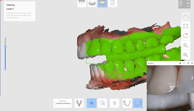
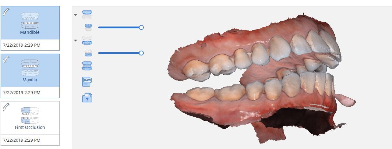
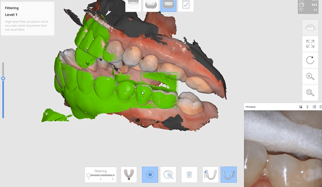
Now as we continue to image in the same catalog box, we can gauge if we are on track as the bite model turns green. Notice how when we move from the upper arch to the lower arch, across an open bite, and we maintain a green active box and green model formation, we can rest assured that our case is mounted correctly.

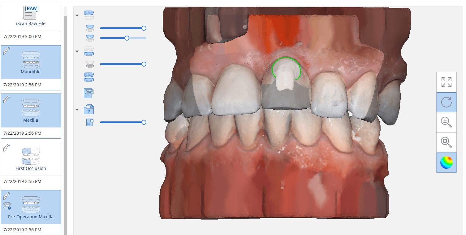
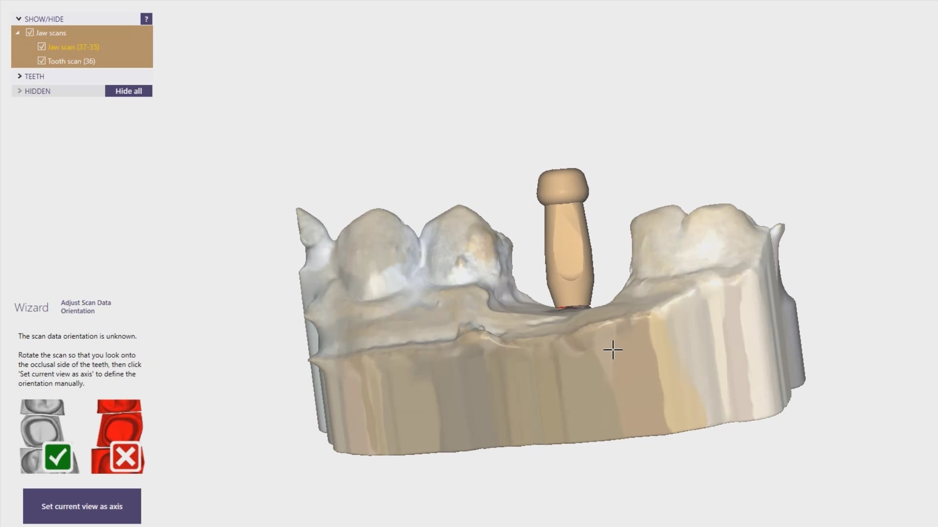
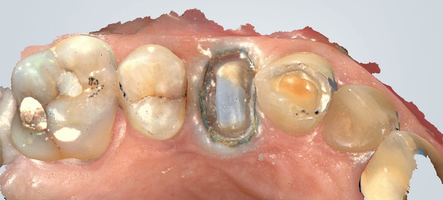
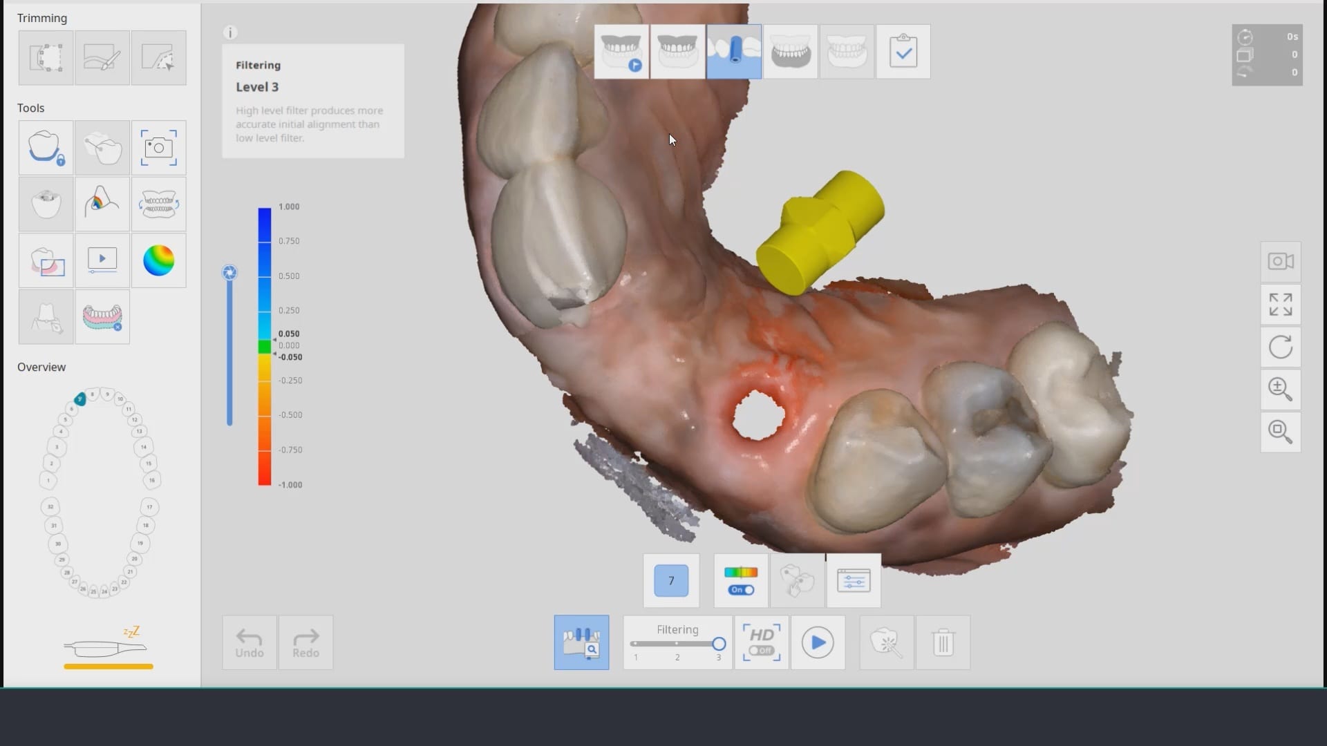
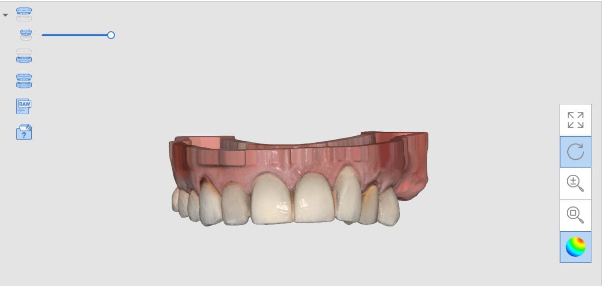
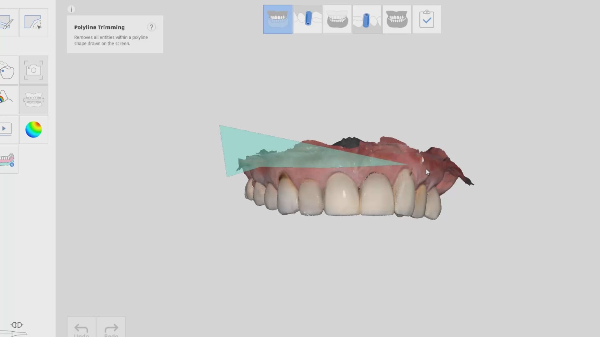
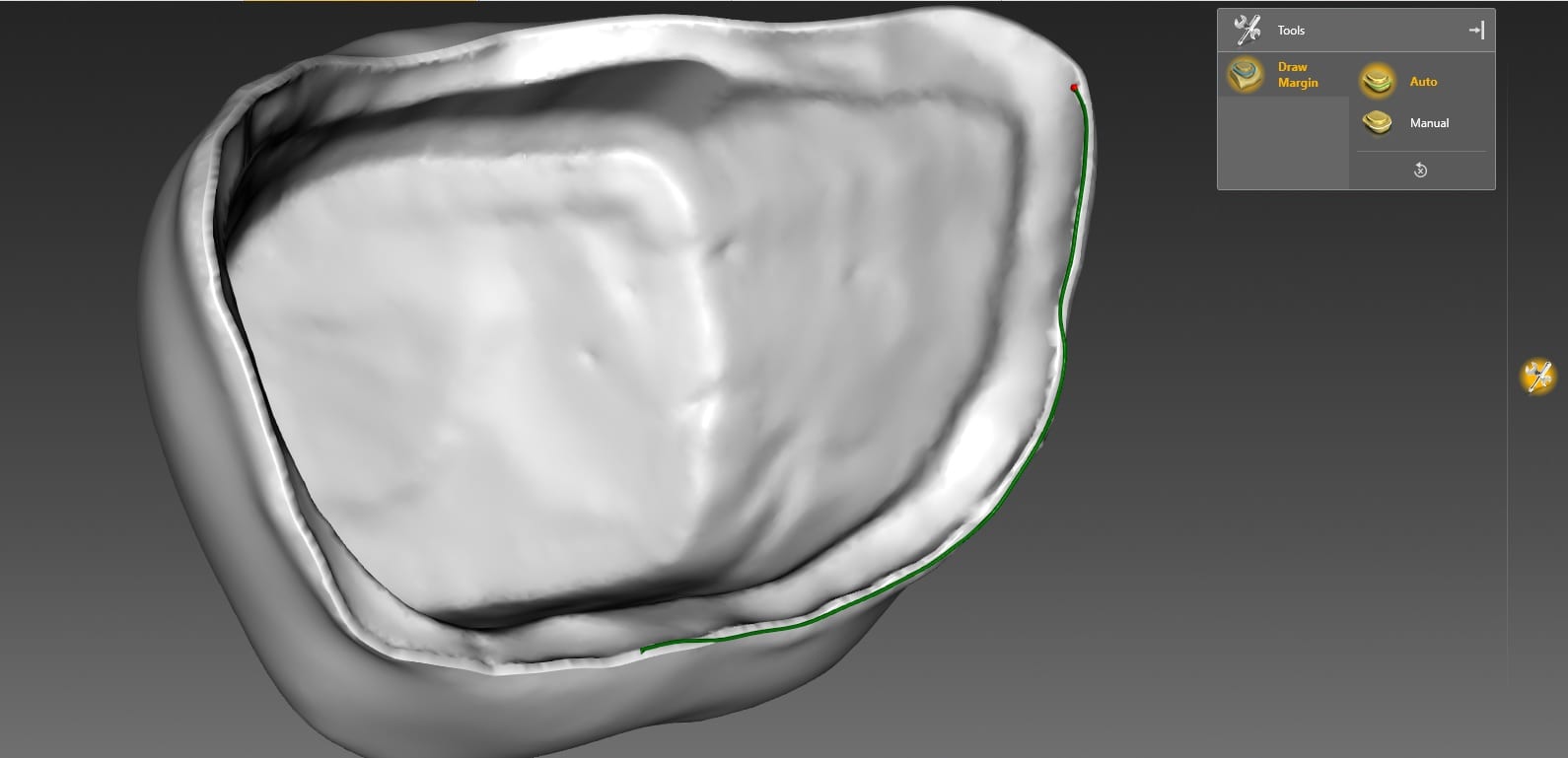
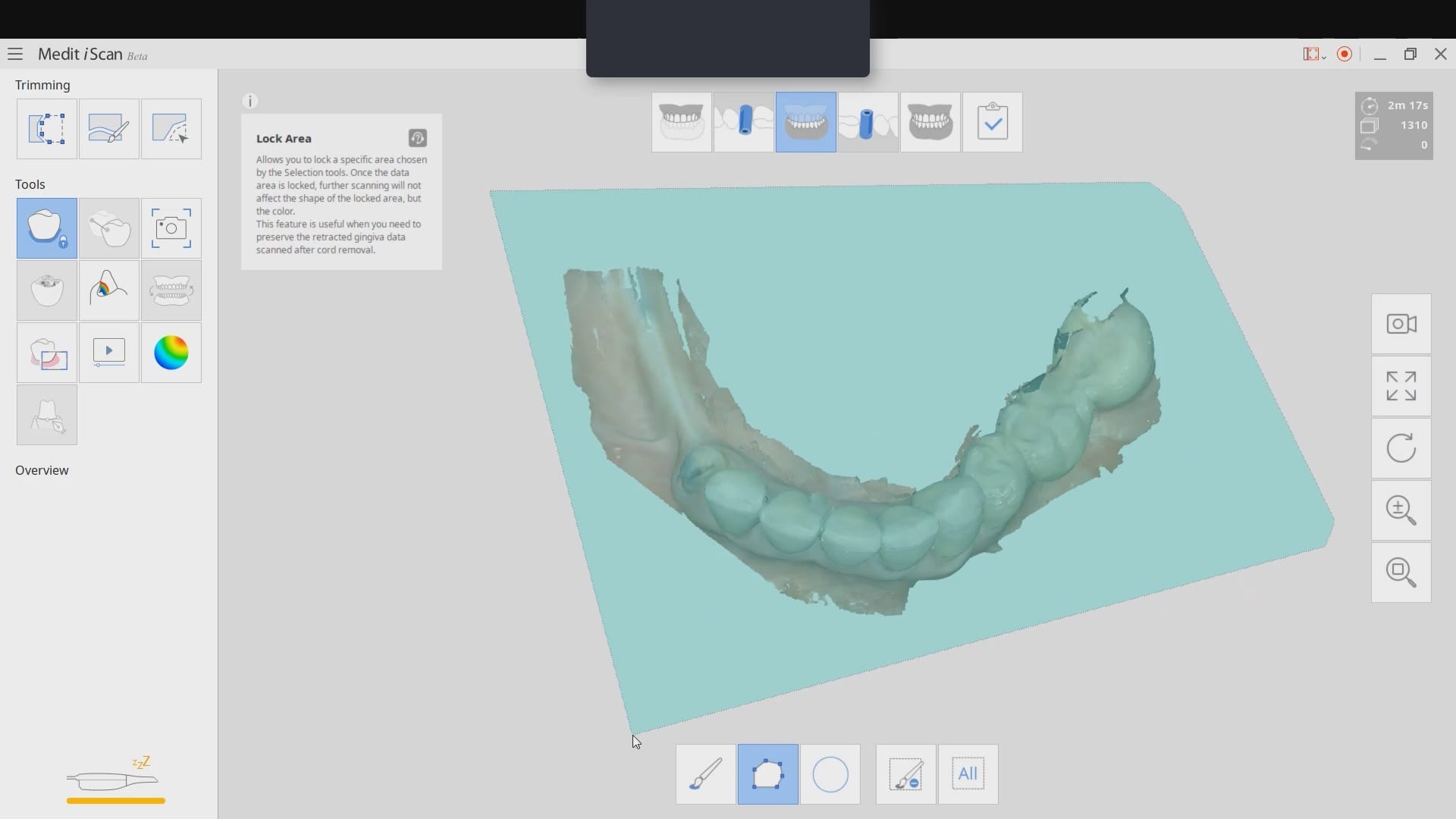
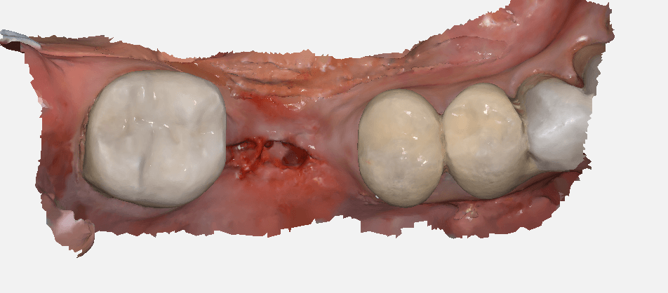
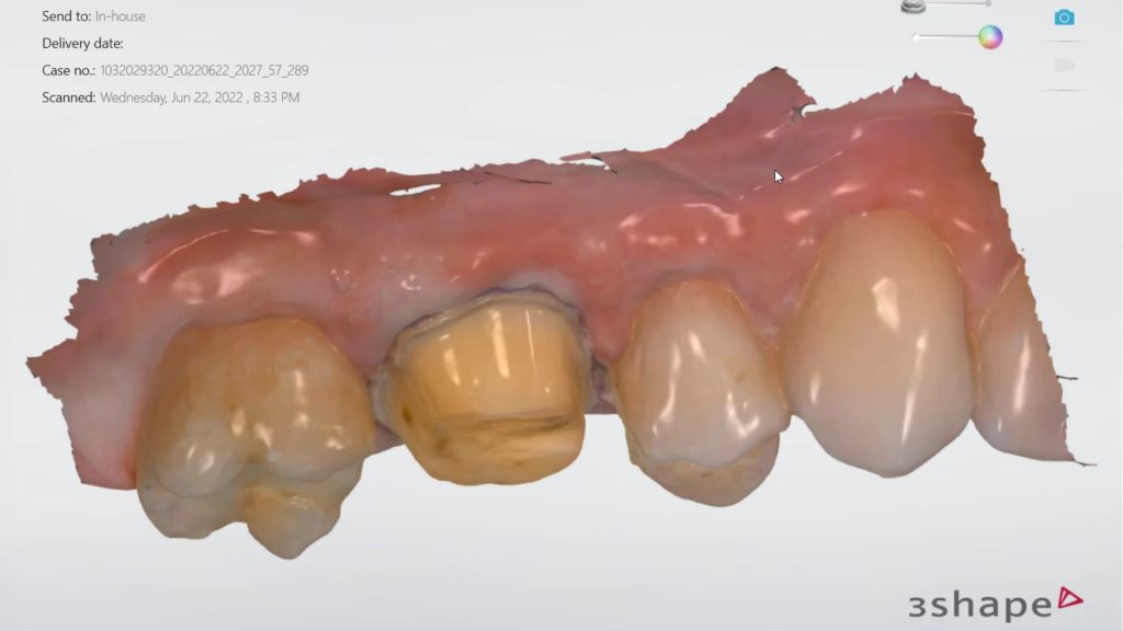
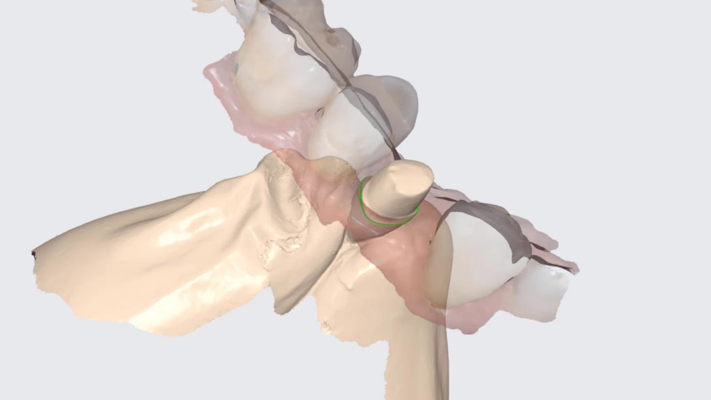
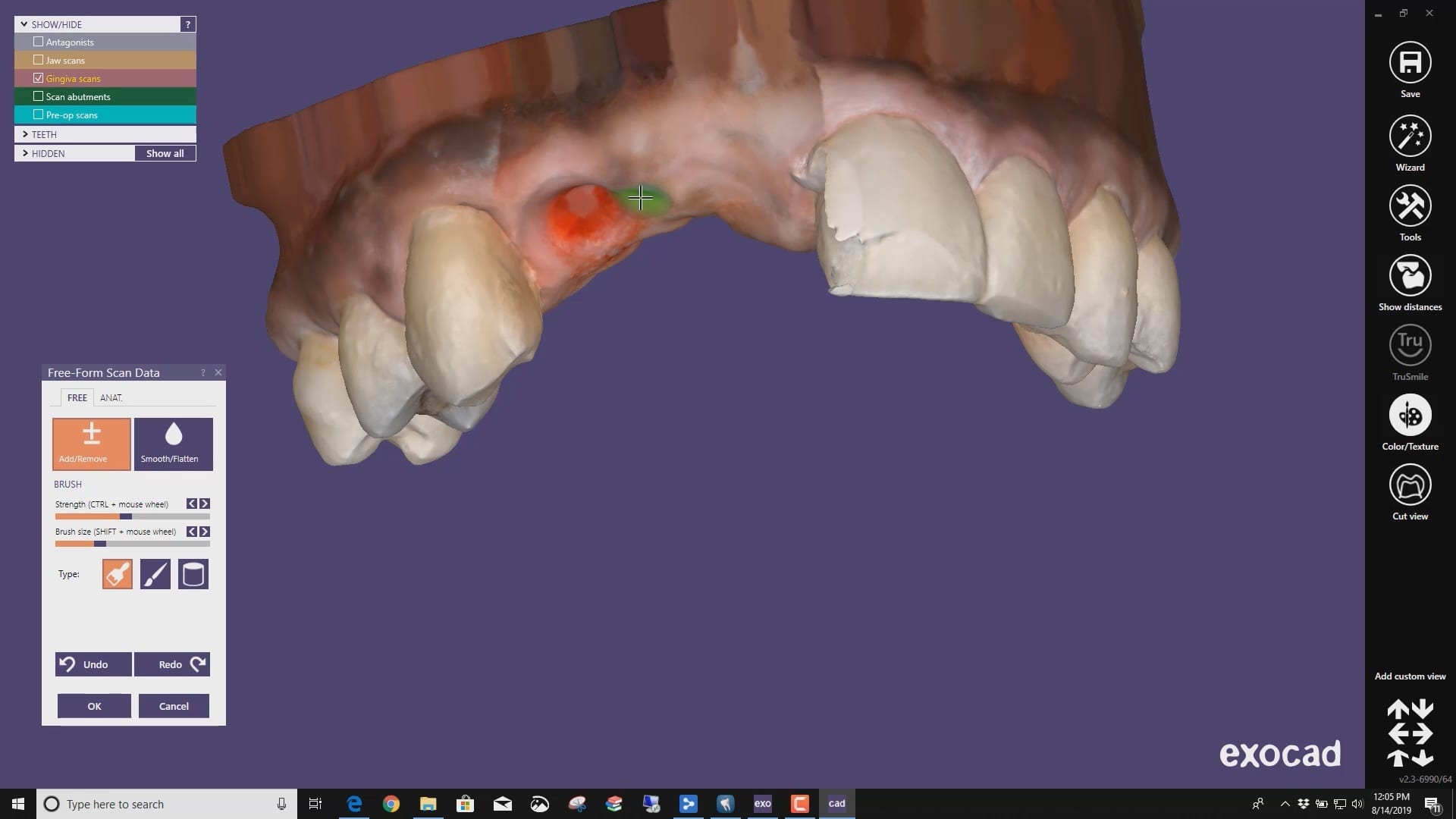
The new Medit i500 software will feature the ability to mark margins in the imaging step before you import the case into a CAD software or send it to the lab. In this article we showcase a case where a 12 year old implant crown needed replacement. The pre-op images were captured, along with the opposing and the bite.

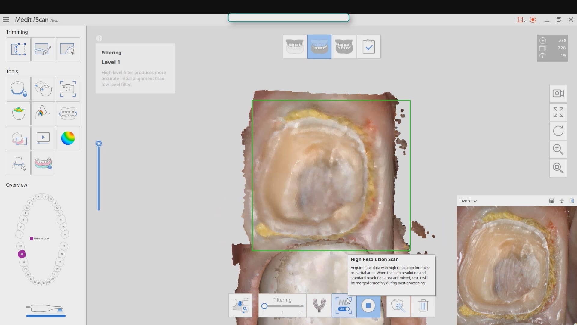
After the area was anesthetized and the crown was removed, expasyl was used to achieve hemostasis and tissue retraction. The margins of the abutment were imaged. Note how we used a feature in the Medit scanner to change the scan light from blue to white, which allows you to pick up red (blood and tissue) that is normally difficult to capture.
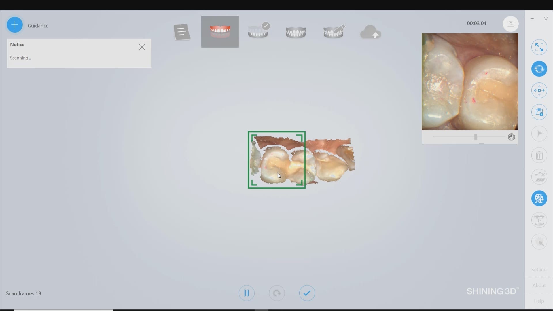
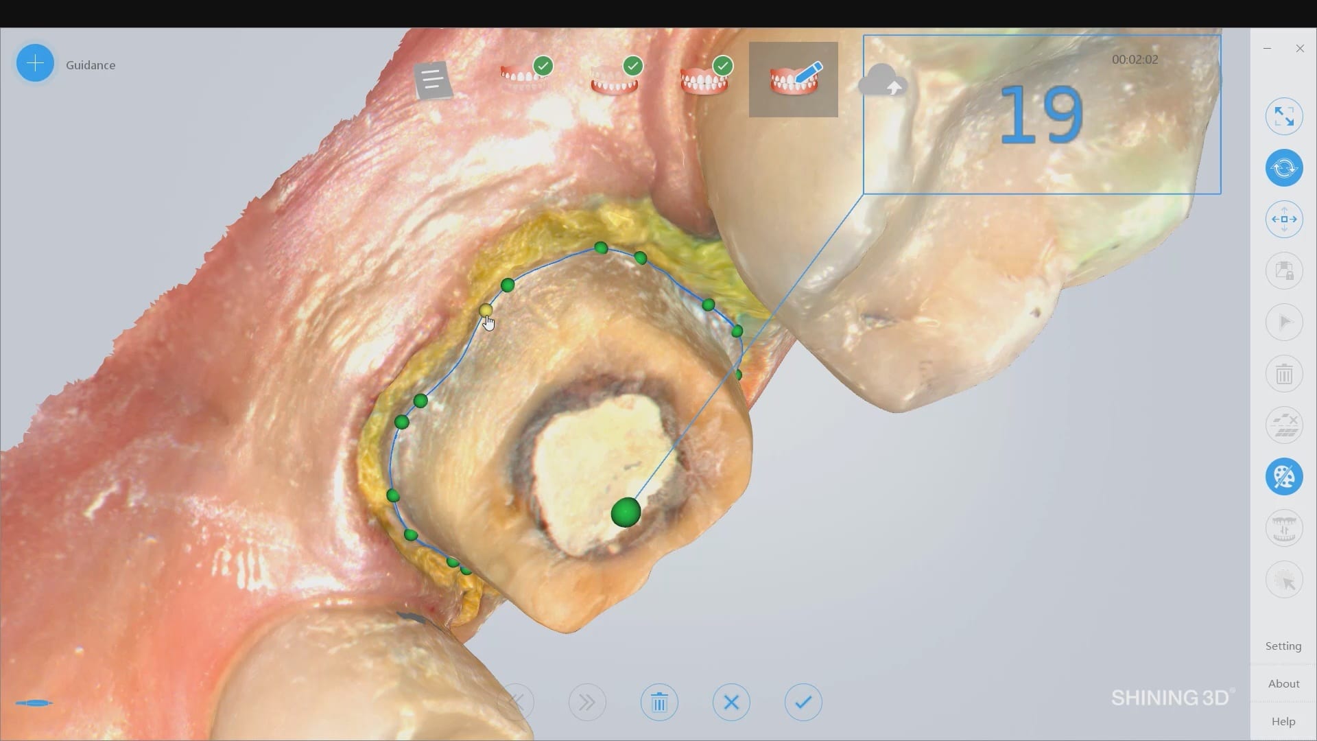
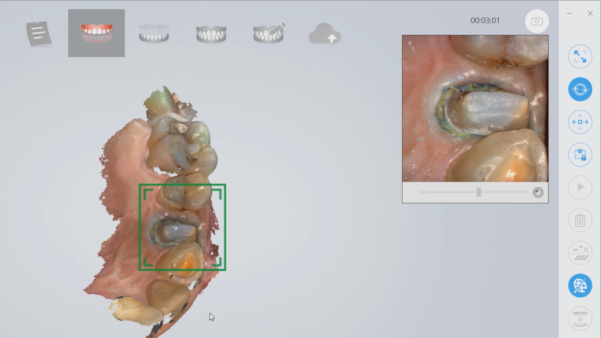
Once the margins were captured, we activated the margination tool. You highlight the area you want to address and the meshwork is calculated and processed locally, where you can then designate your margins that are exported to CAD software along with the jaw model, the opposing, the pre-op and the bite.
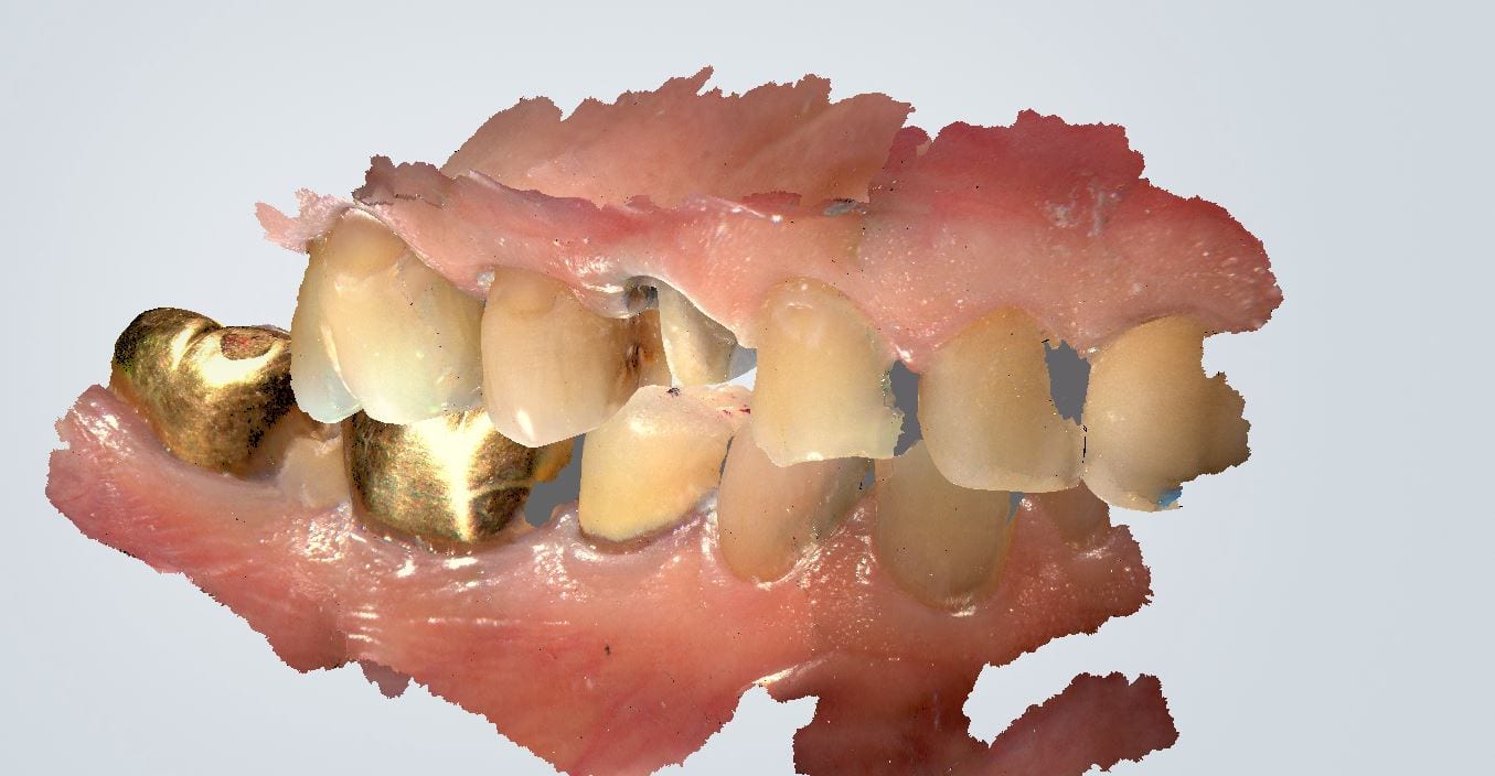
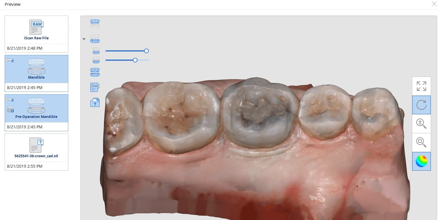
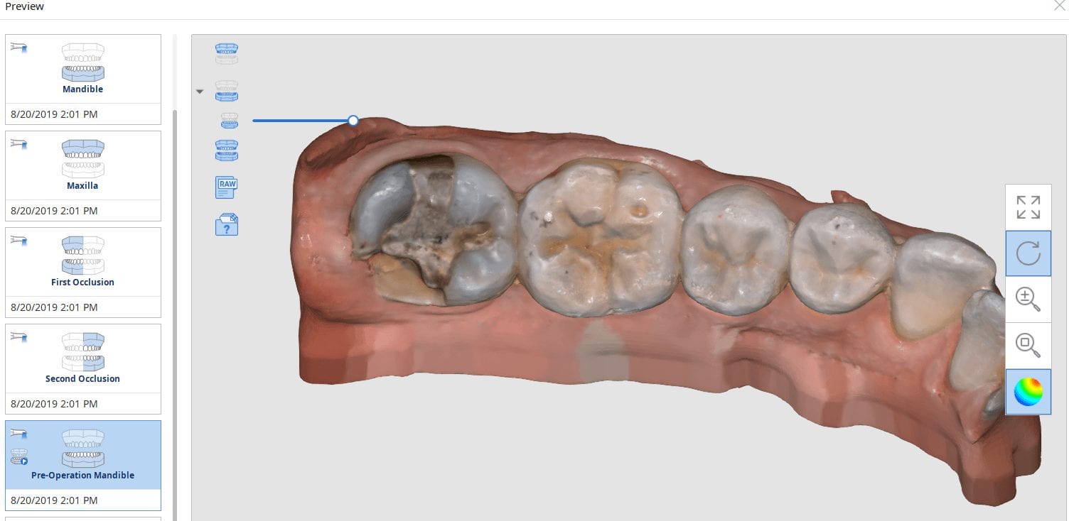
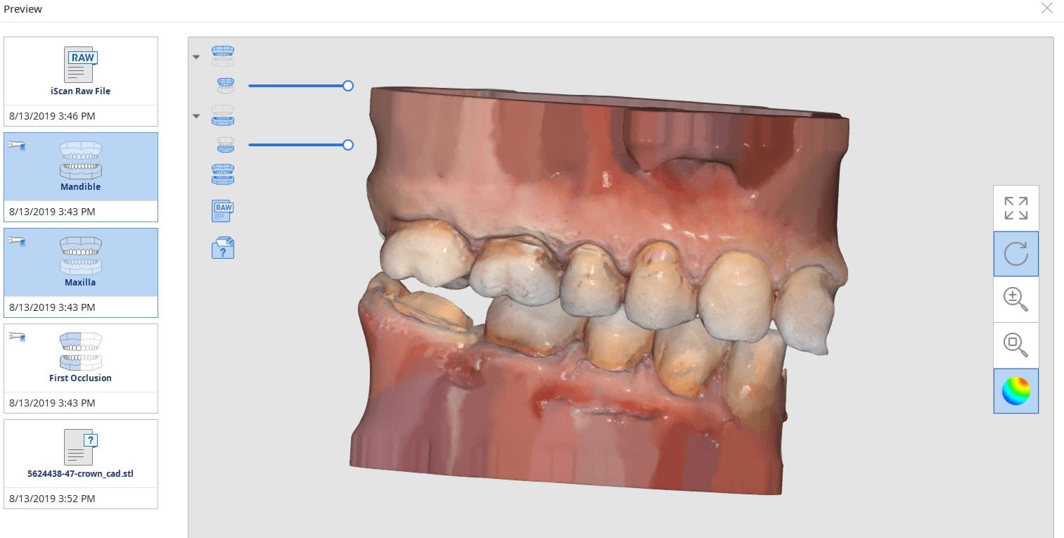
This is a preview of the models that you can export and send to a lab or take directly to design software for chairside milling.
Alternatively, the traditional way would be to not place the margins in the native Medit software and to place it in the CAD software itself. As you can see both options are very viable and you do not lose any resolution of the scanned data between the imaging program or the design software.


A lot of our users are migrating to SSD Drives which greatly speeds up processing and graphics rendering in intense software applications. When you are capturing scans with the Medit i500 you can quickly fill up your hard drive with law videos (which is technically a series of thousands of images) and when you process the case, the data is converted into small 30-50 MB size digital models
In previous versions of the software that data was only stored on your local machine, which meant you could not log into another computer to add or edit your live video images. You now can sync the data through the cloud so you can access it anywhere, or you can delete the raw footage from the preview screen. In previous versions you would have to search hidden folders to find this data, but now it is readily available and you can dump the data with one click. You do not delete your models in this situation.

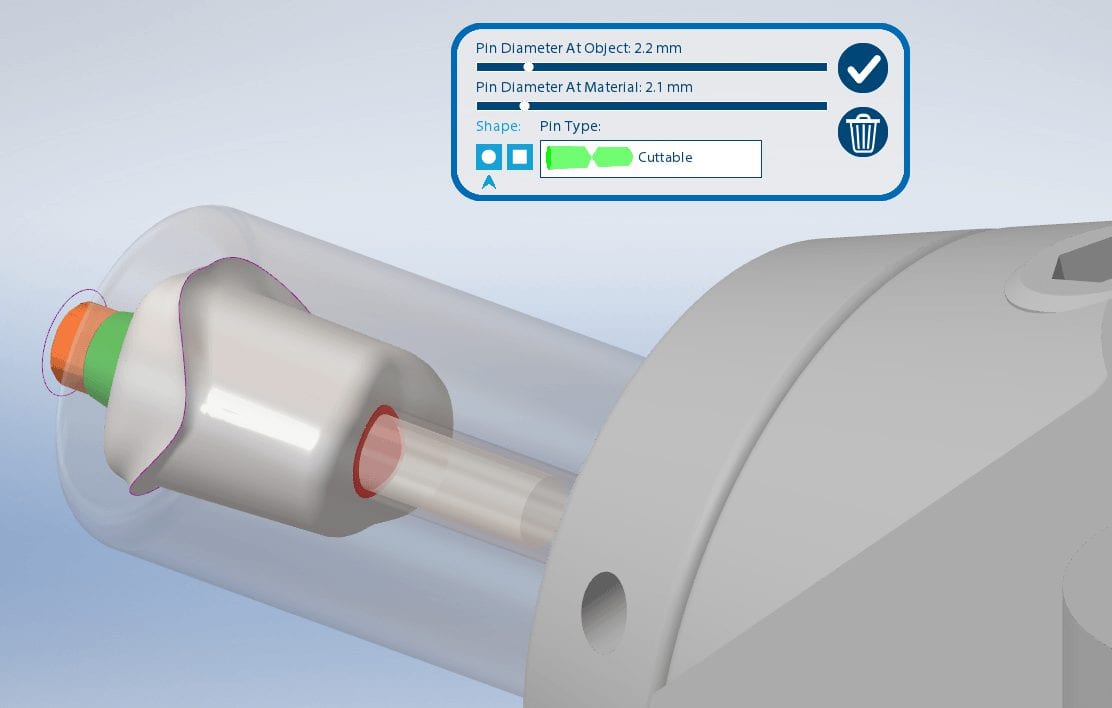

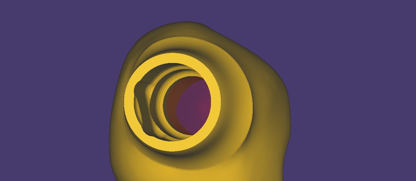
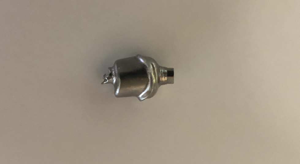
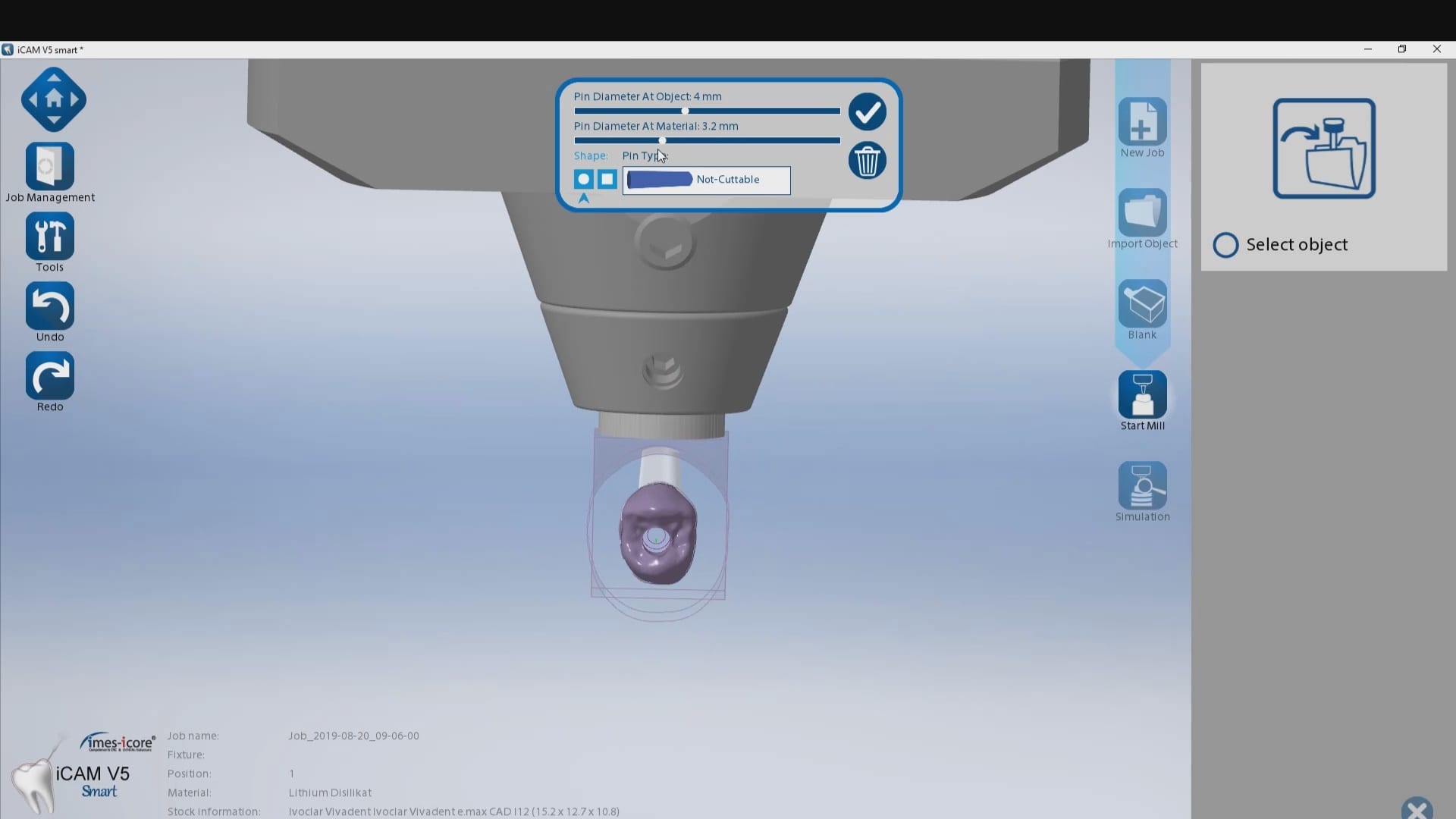
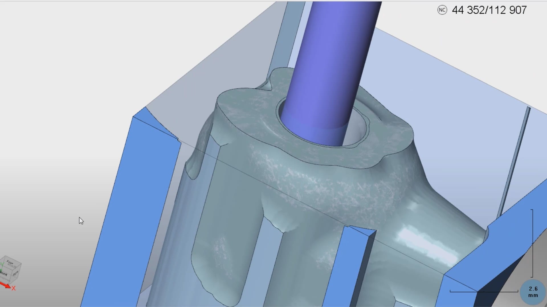
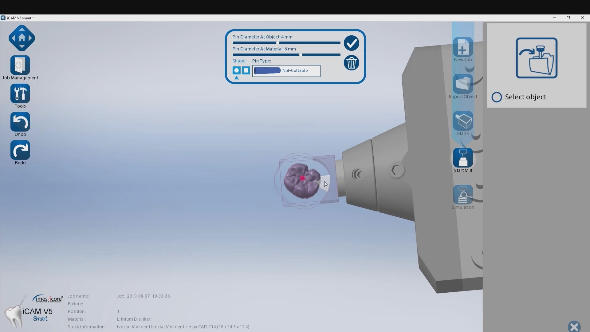
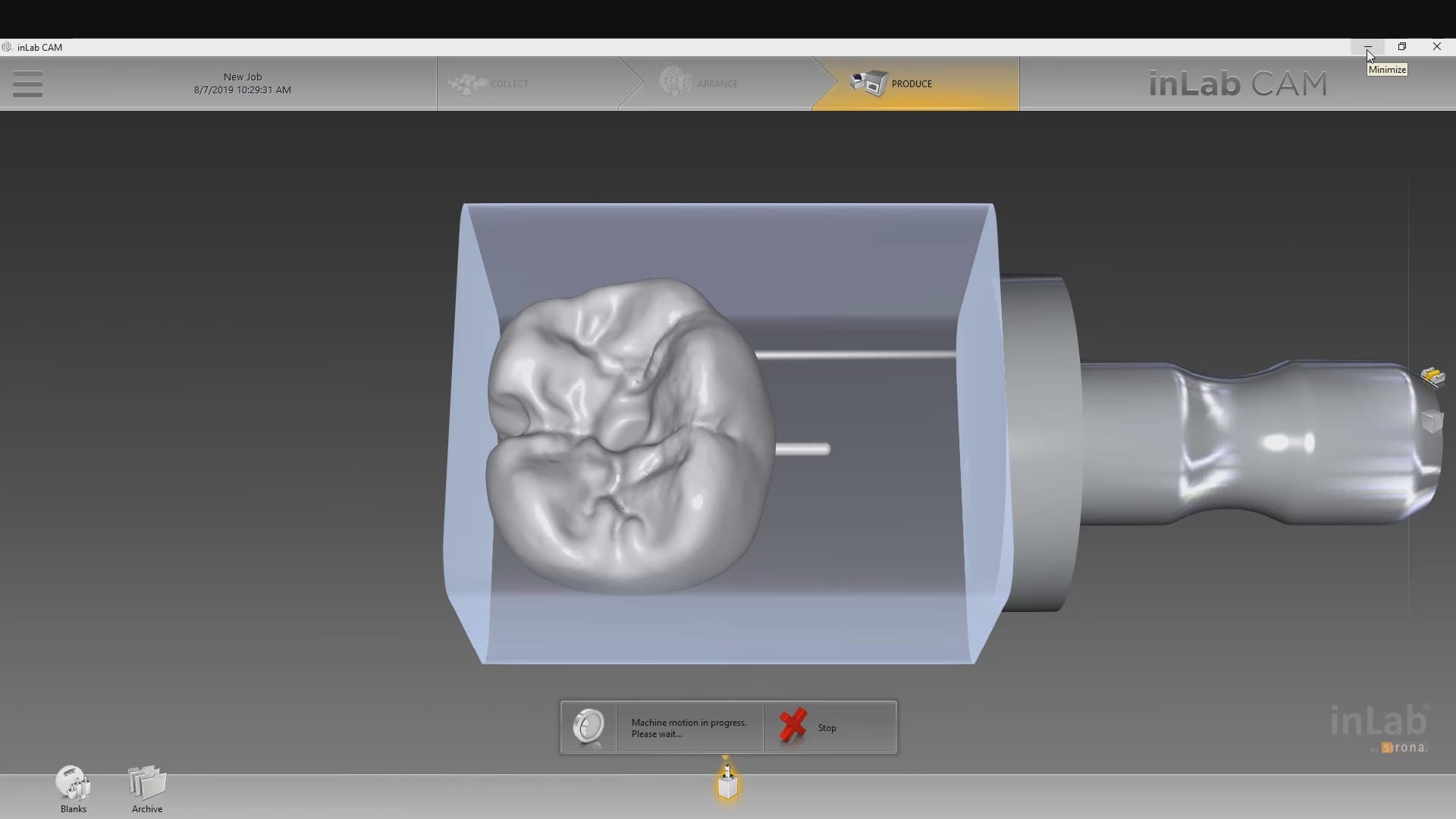
Titanium blanks are the hottest topic in digital dentistry in 2019. A lot of new milling machines can mill emax, zirconia, and custom metal abutments.
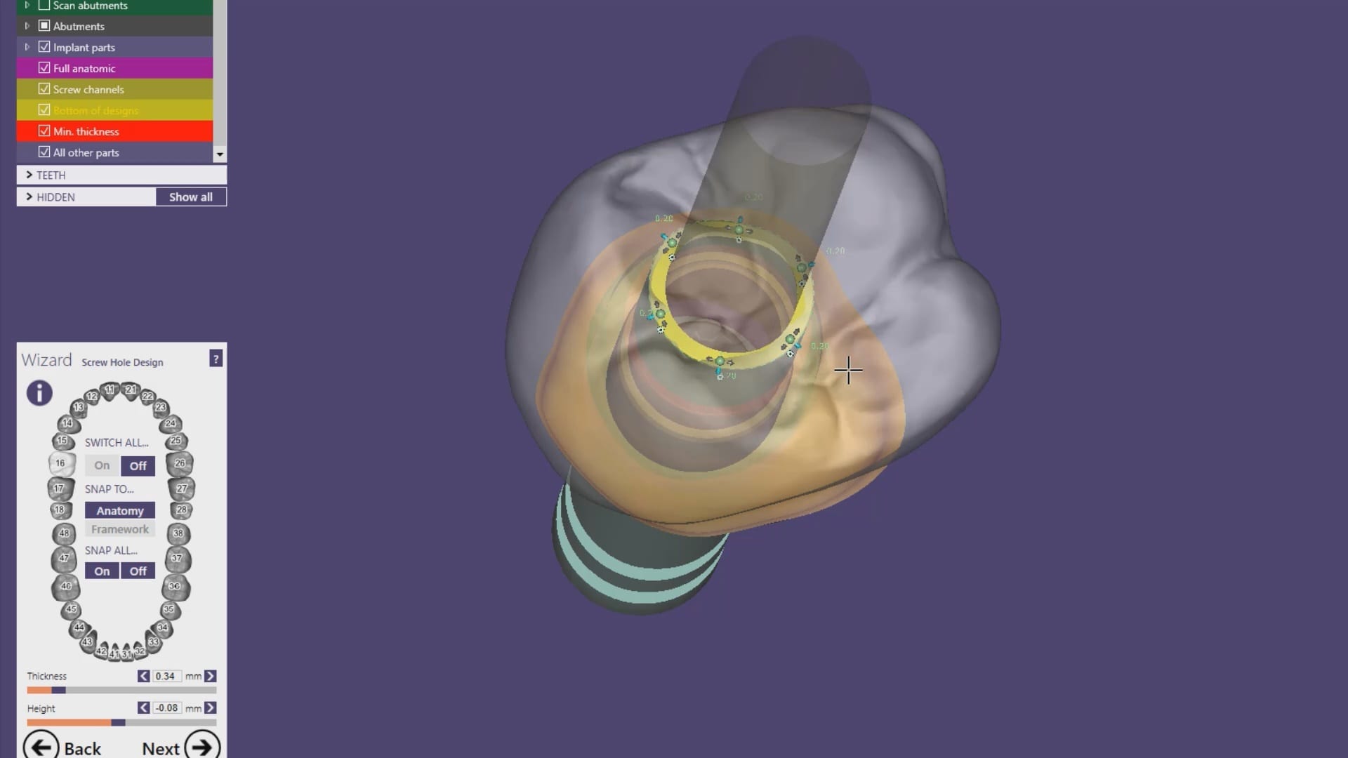
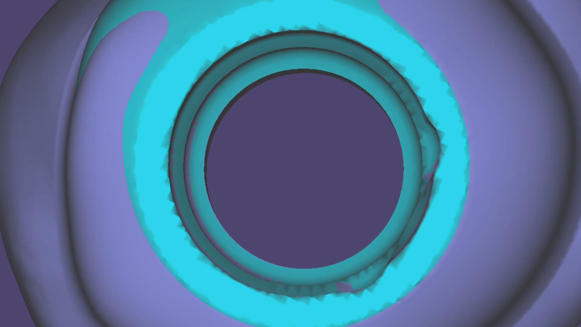
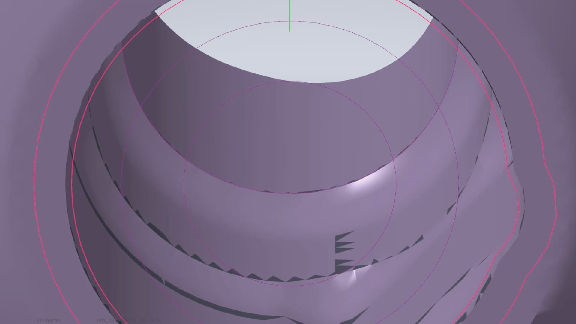
One of the parameters to keep in mind when milling them is the diameter of the screw access channel. Most CAM will carve them out but leave a lot of finishing processes remaining.

We’ve tested quite a lot of mills with the imes icore coritec one and the milbox cam software. If you set the settings to 2.5 mm’s , you can pee off the excess sprue material with just finger pressure, dramatically reducing the free hand work that you would have to do.
The pin diameter at object and at material under 2.5 mm’s will give you inconsistent results.


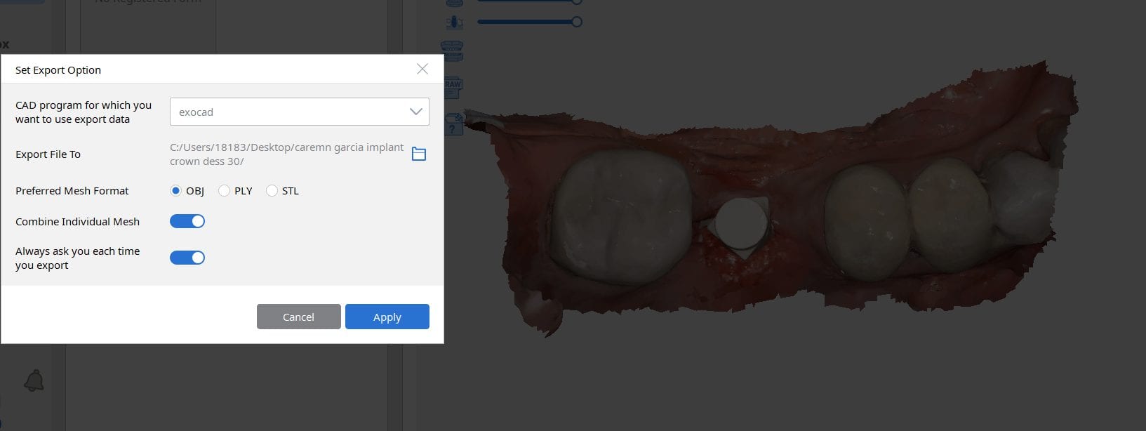
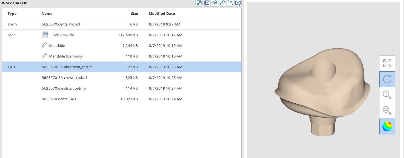
Most scanners will export the jaw model and the scanbody model separately but a new feature on the Medit upcoming software will let you export them as individual models or as a single merged model.
There are design advantages to both scenarios based on the practitioners skill level!


There are numerous ways to quickly check a model before taking it to a design software. Windows comes with at least 3 such free software. Another one to have handy is called 3dviewer.net to let you verify models really quickly


You must be logged in to post a comment.