


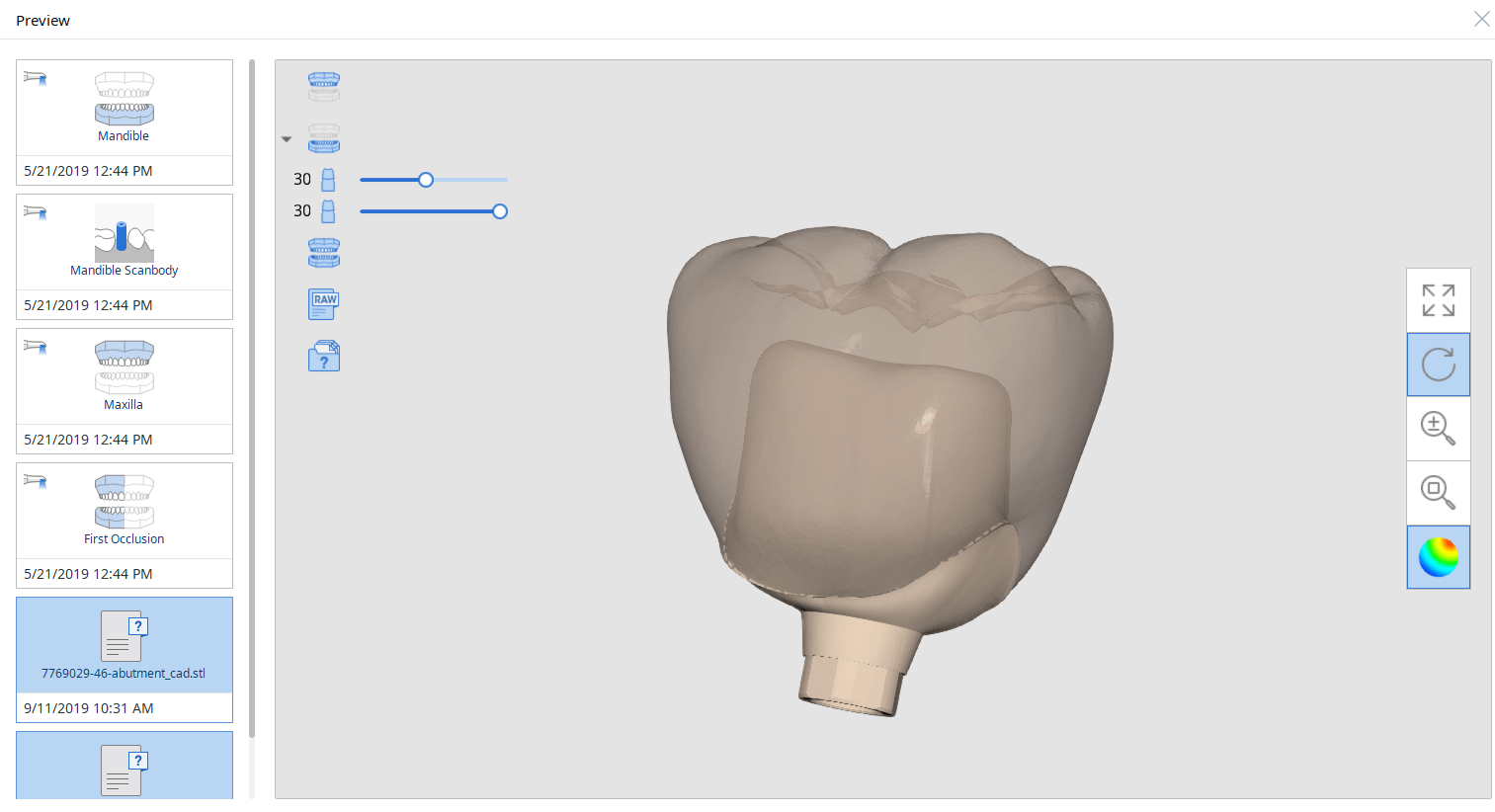
In this article we detail everything you need to capture to design and all on x type of restoration so you can quickly print a prosthesis and deliver it to your patient as quickly after surgery as possible. We think it is best to start with the end in mind and work backwards to the models you need to capture.
Models Needed to Design
These are the models you need to bring into exocad per arch. Of course, you can bring in more information into the equation if you chose to:
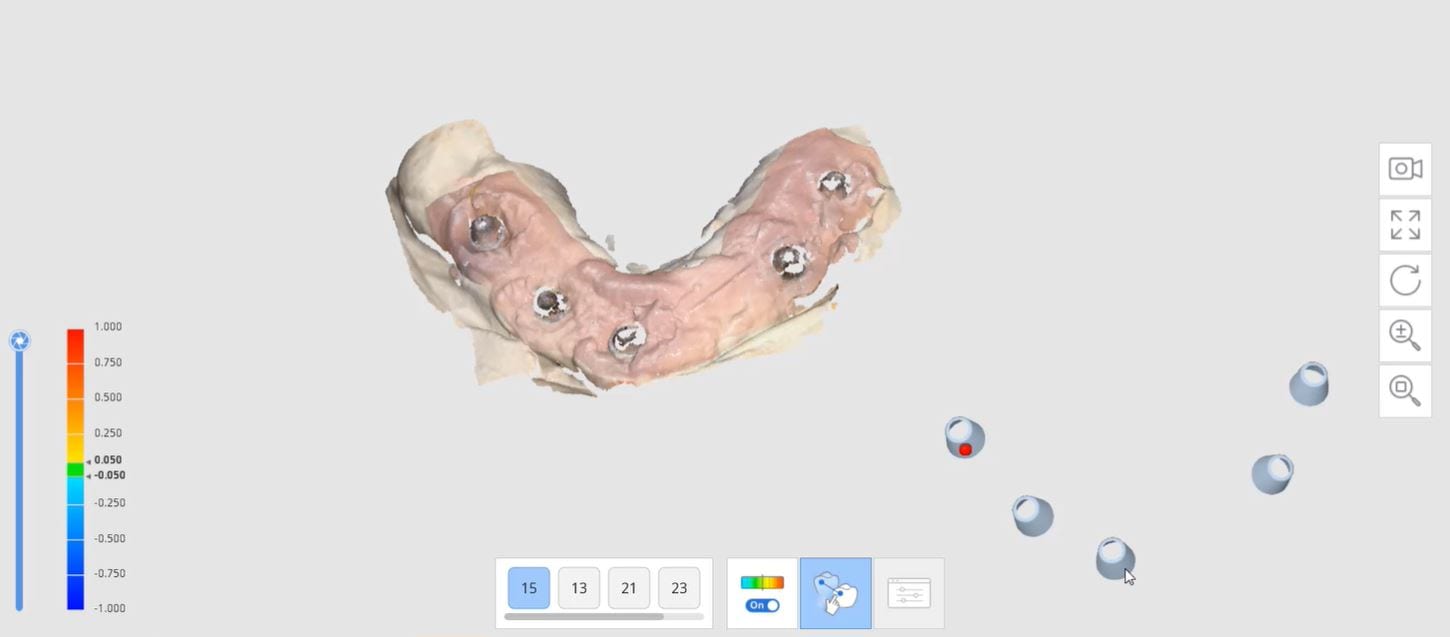
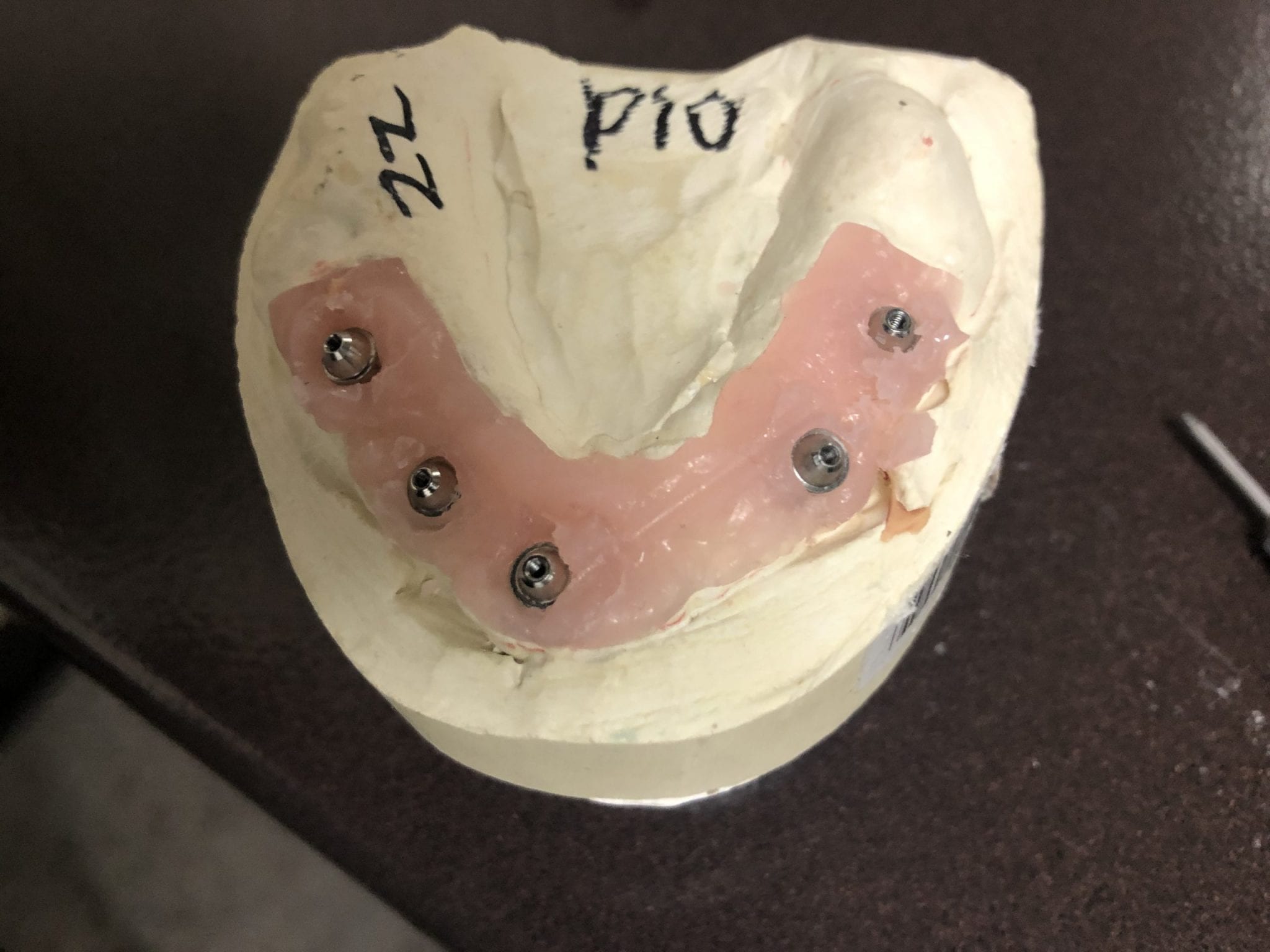
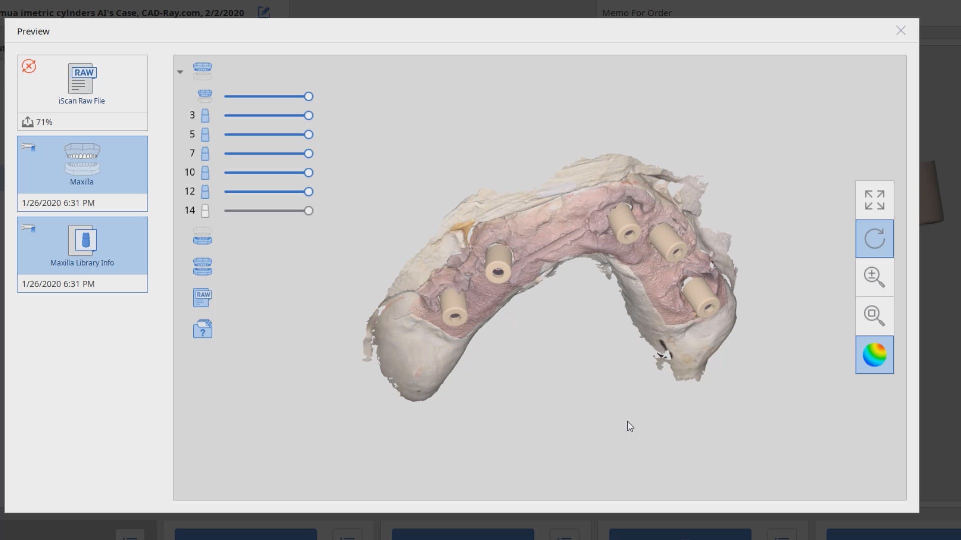
- Tissue scan (ideally when sutured and not a bloody field). This is usually captured with an intra-oral scanner. Some take an alginate of the arch and scan it with a desktop scanner.
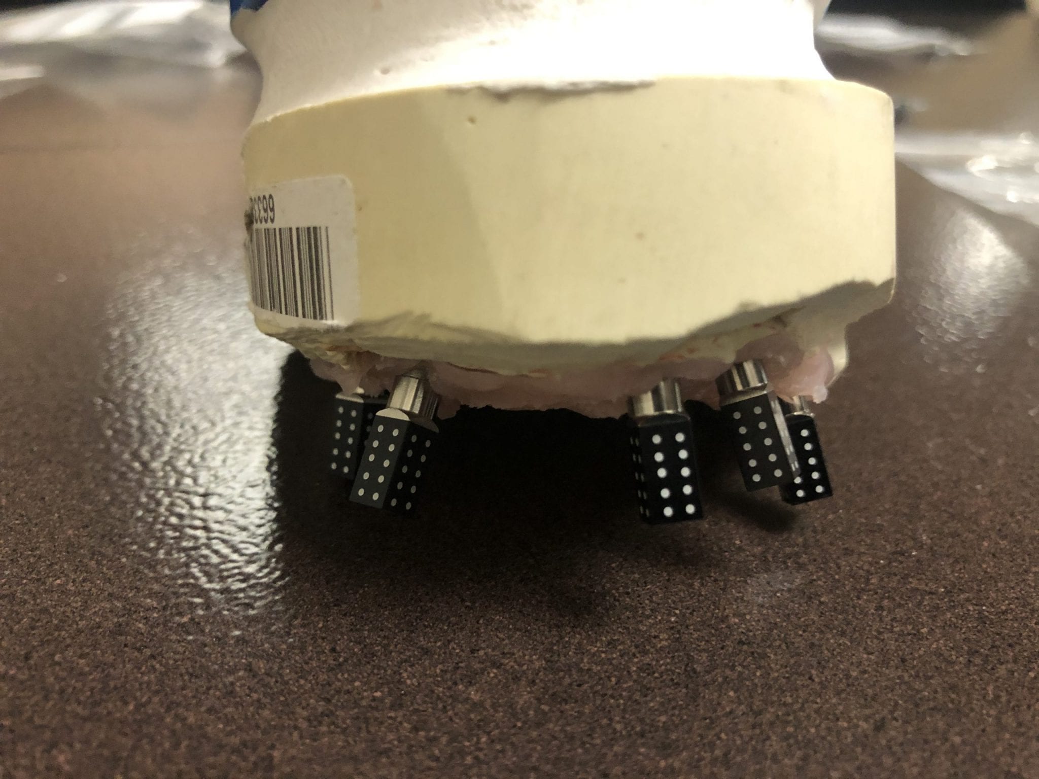
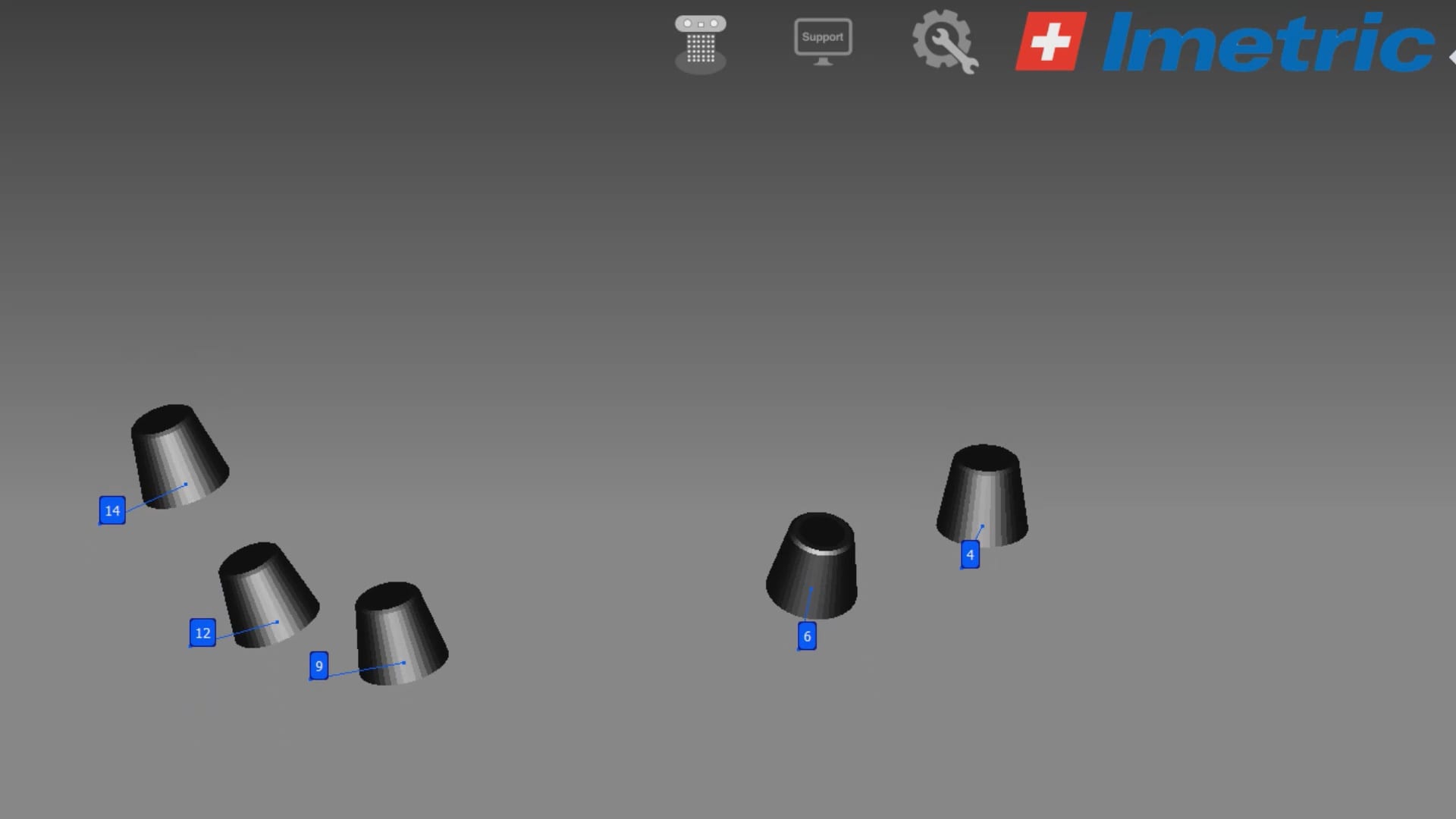
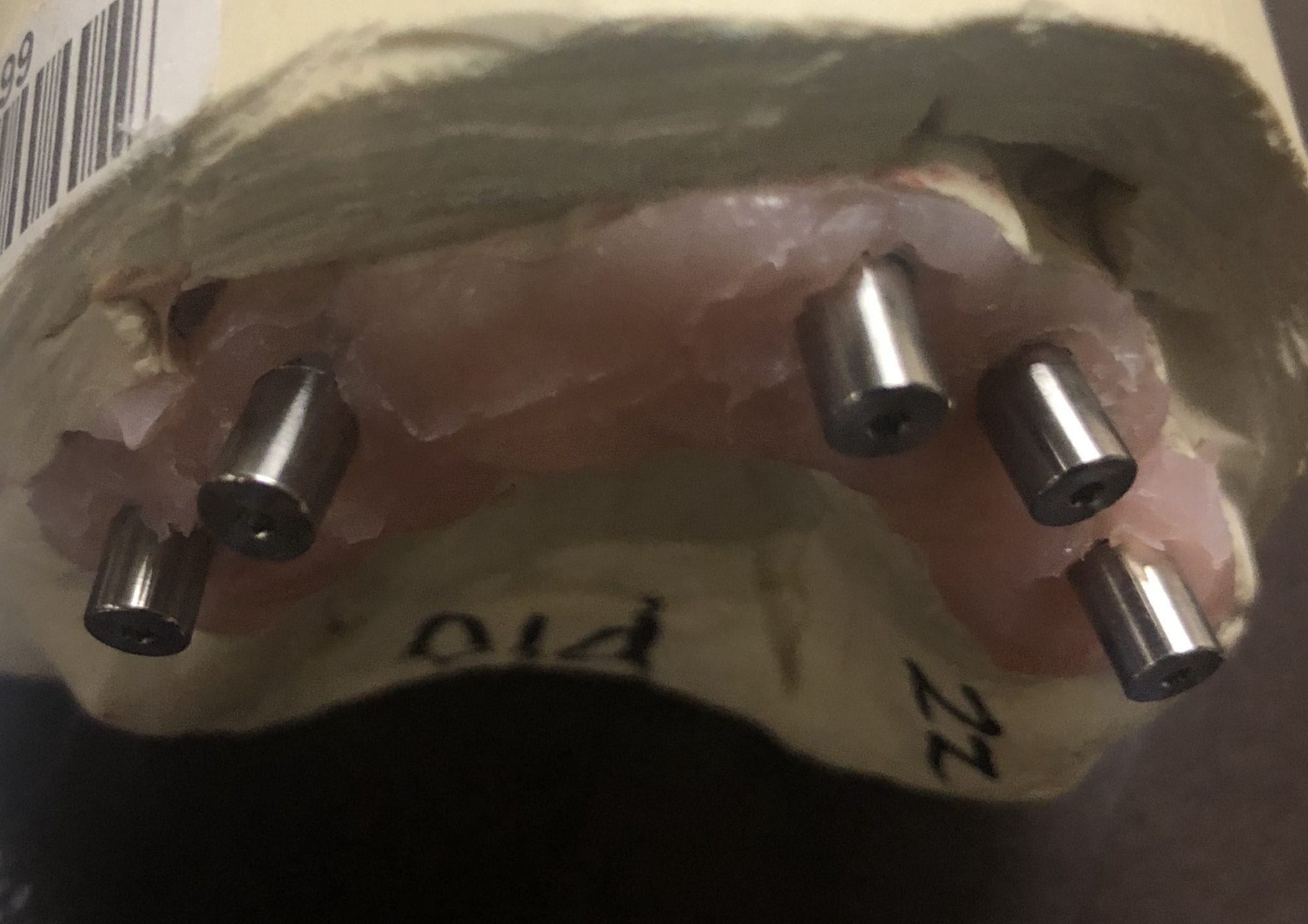
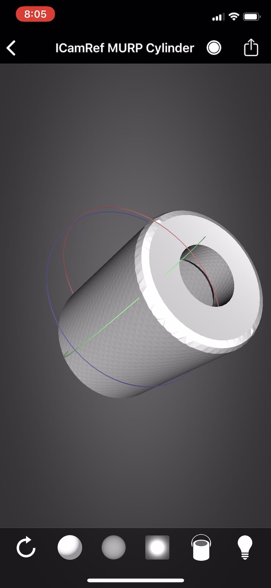
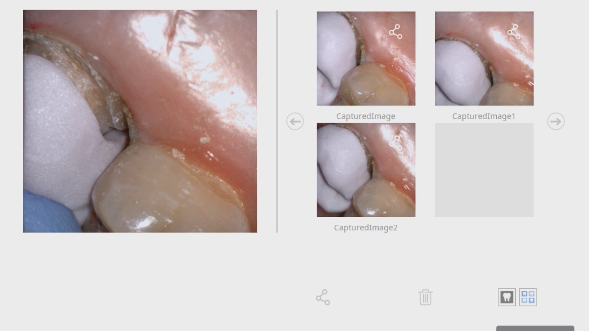
- Implant locations, which are the multi-unit abutment margins. These are captured in a variety of ways, all of which have to address the limitations of scanning edentulous flat and symmetric surfaces which introduce Veersing Errors. These options include extra-oral photogrammetry, intra-oral photogrammetry, and/or implant suprastructures that reduce or eliminate scanning errors, like the Scan Ladder, io connect from TruAbutment, etc…
- Preop Scan, or more ideally a wax up scan to the correct vertical dimension
- A designer also ideally would want the opposing model and buccal bites as well.
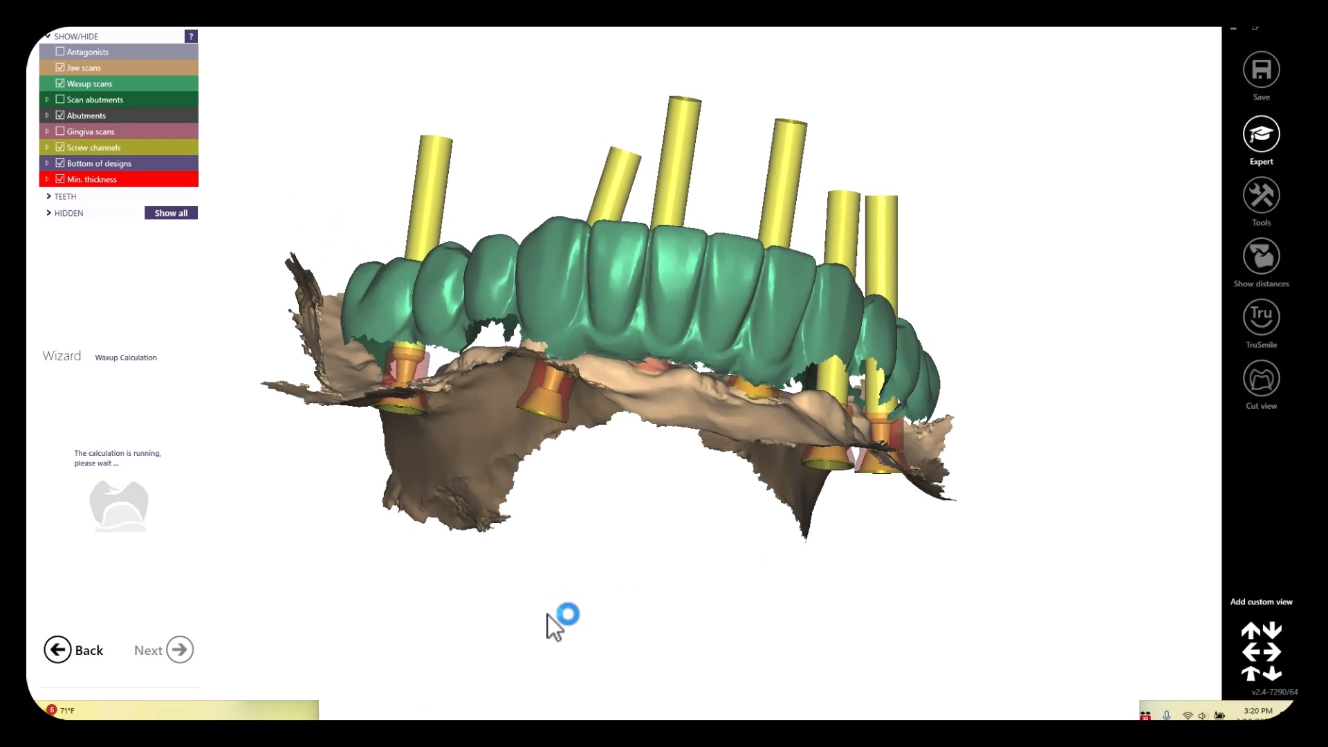
All of these models need to be properly related to each other which is an endeavor in itself. All of the models listed above are also disciplines of their own and many chapters could be devoted to each topic. Assuming you have this information imported into CAD software correctly, you can design the temps very quickly and get them into the printer for a temporary
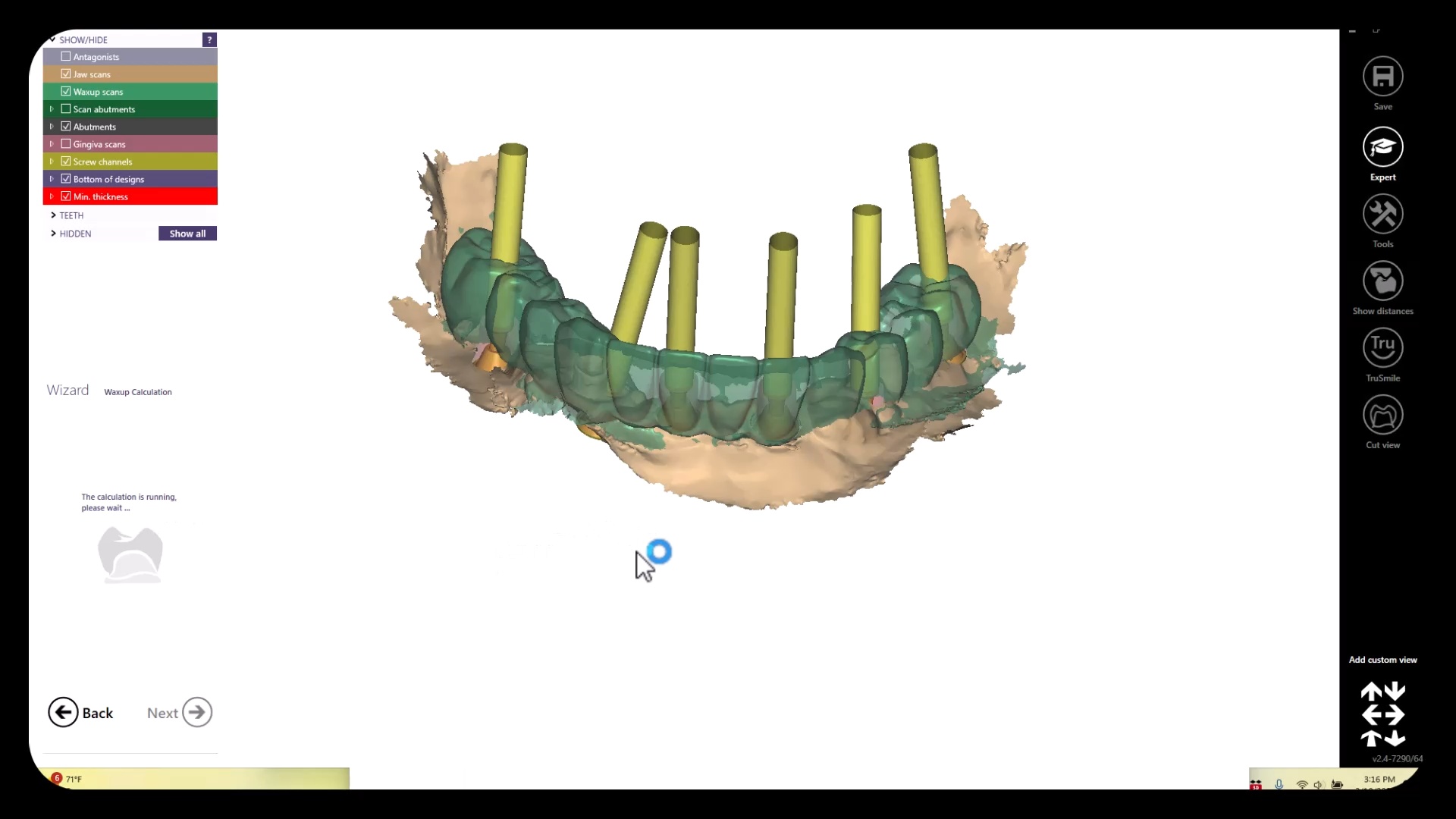
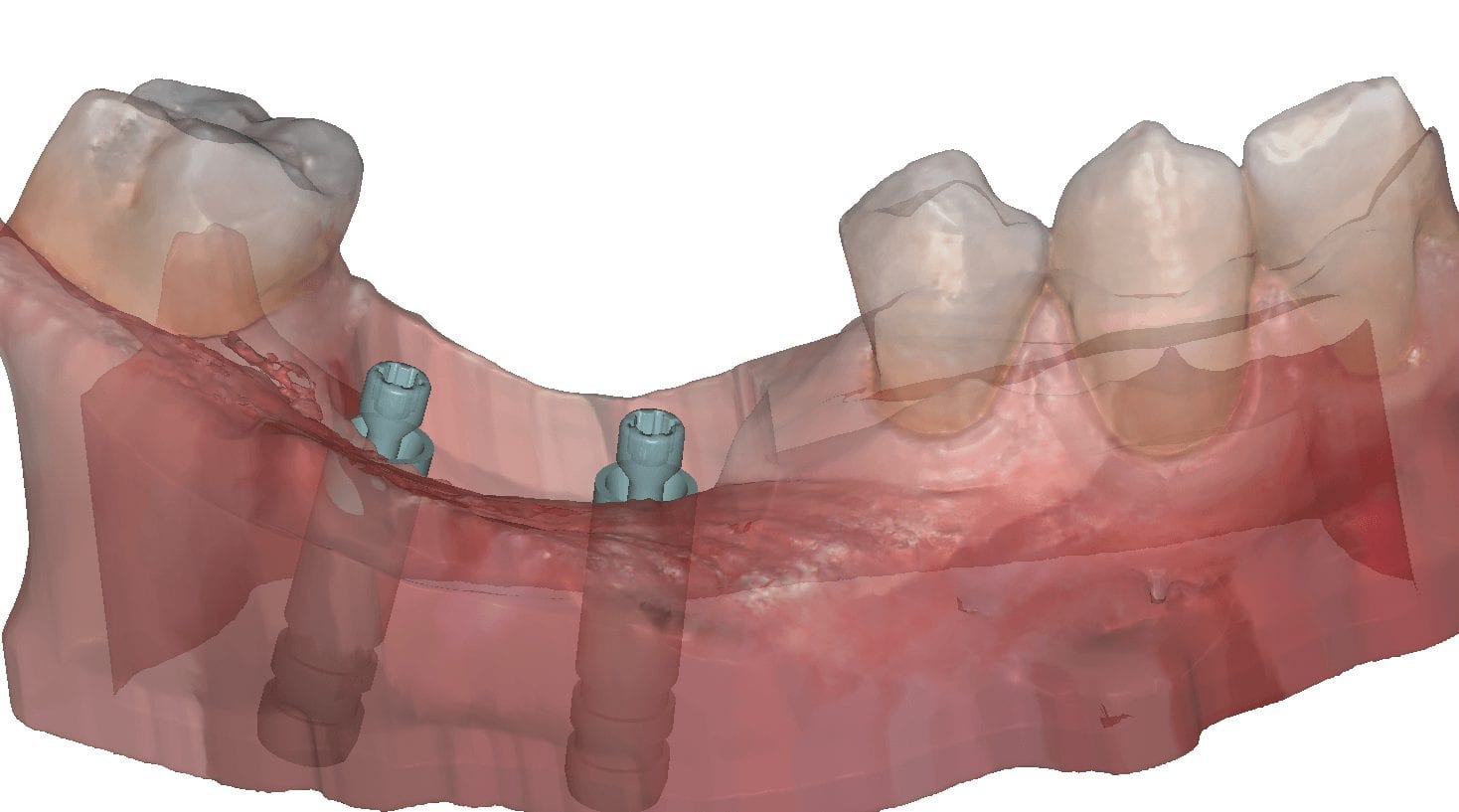
Merging Models to Each Other
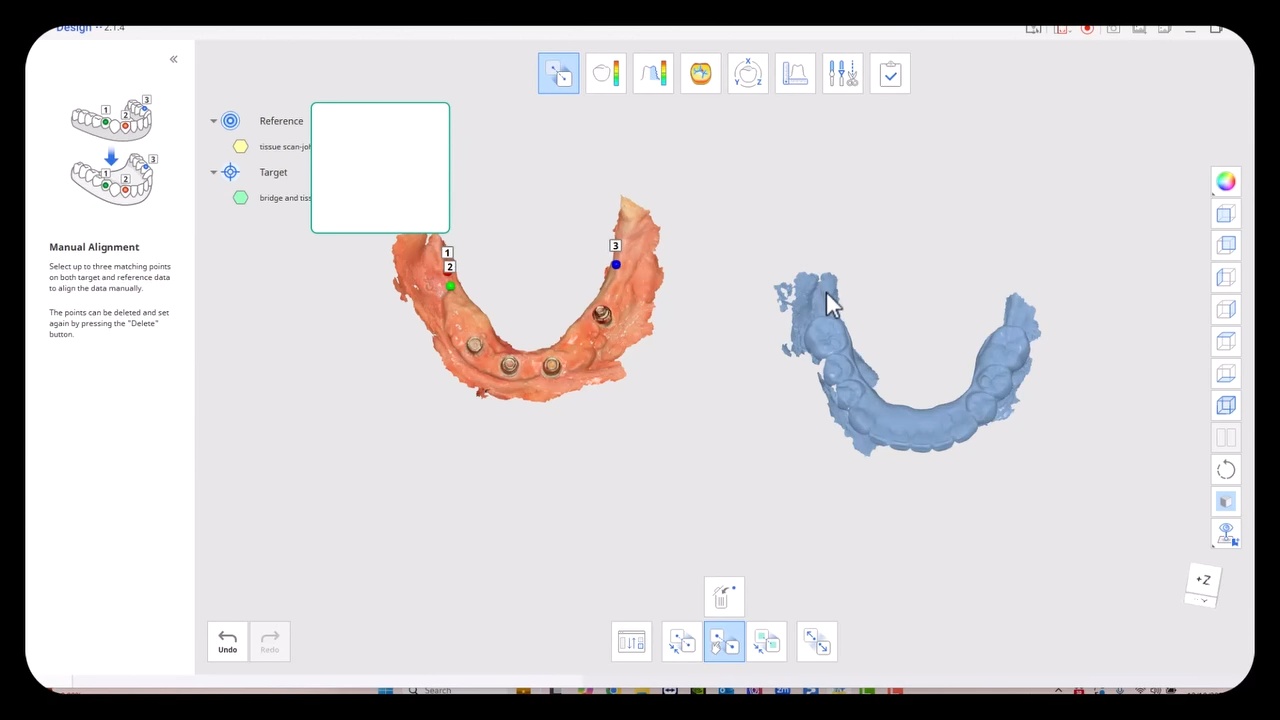
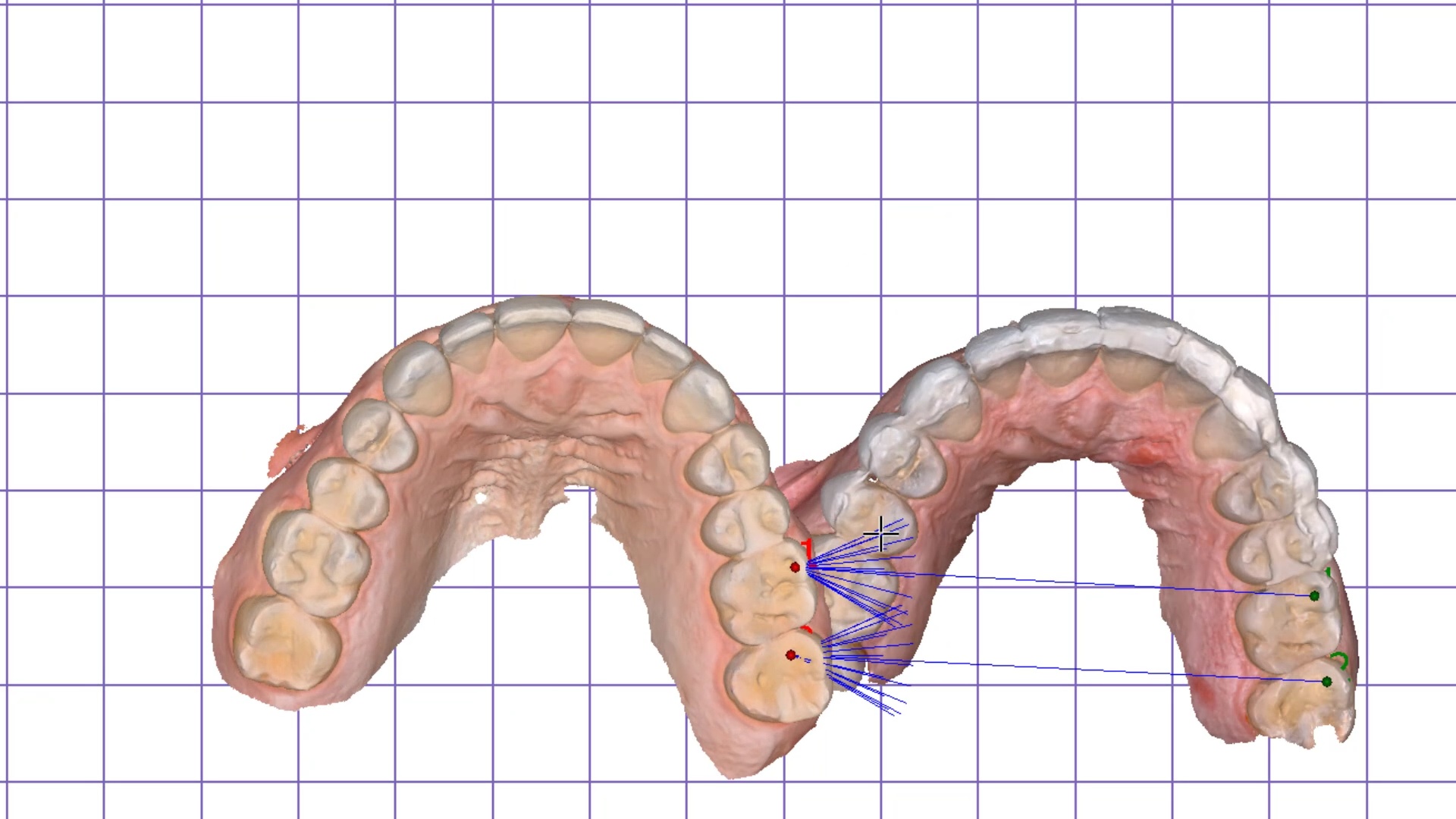
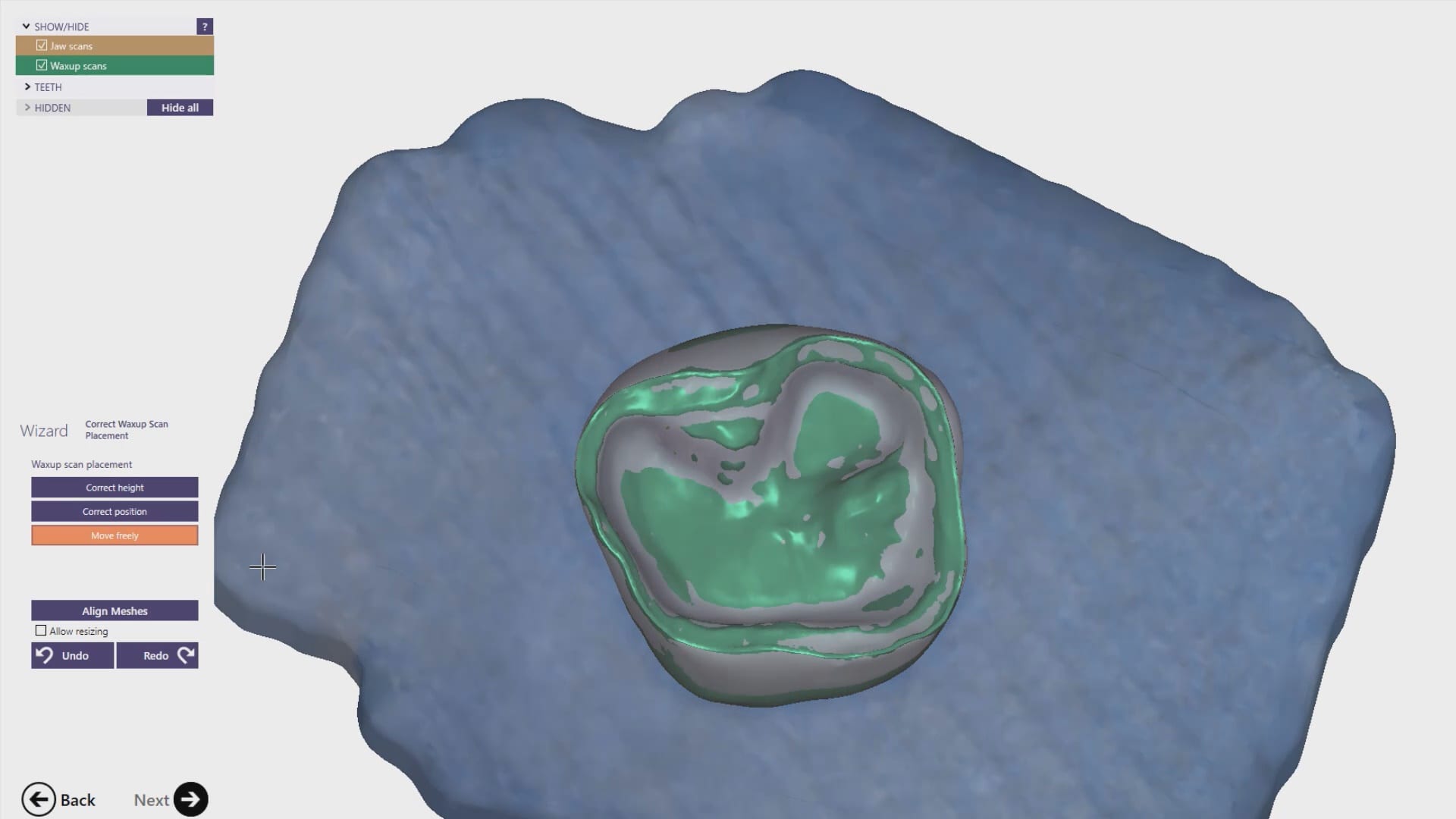
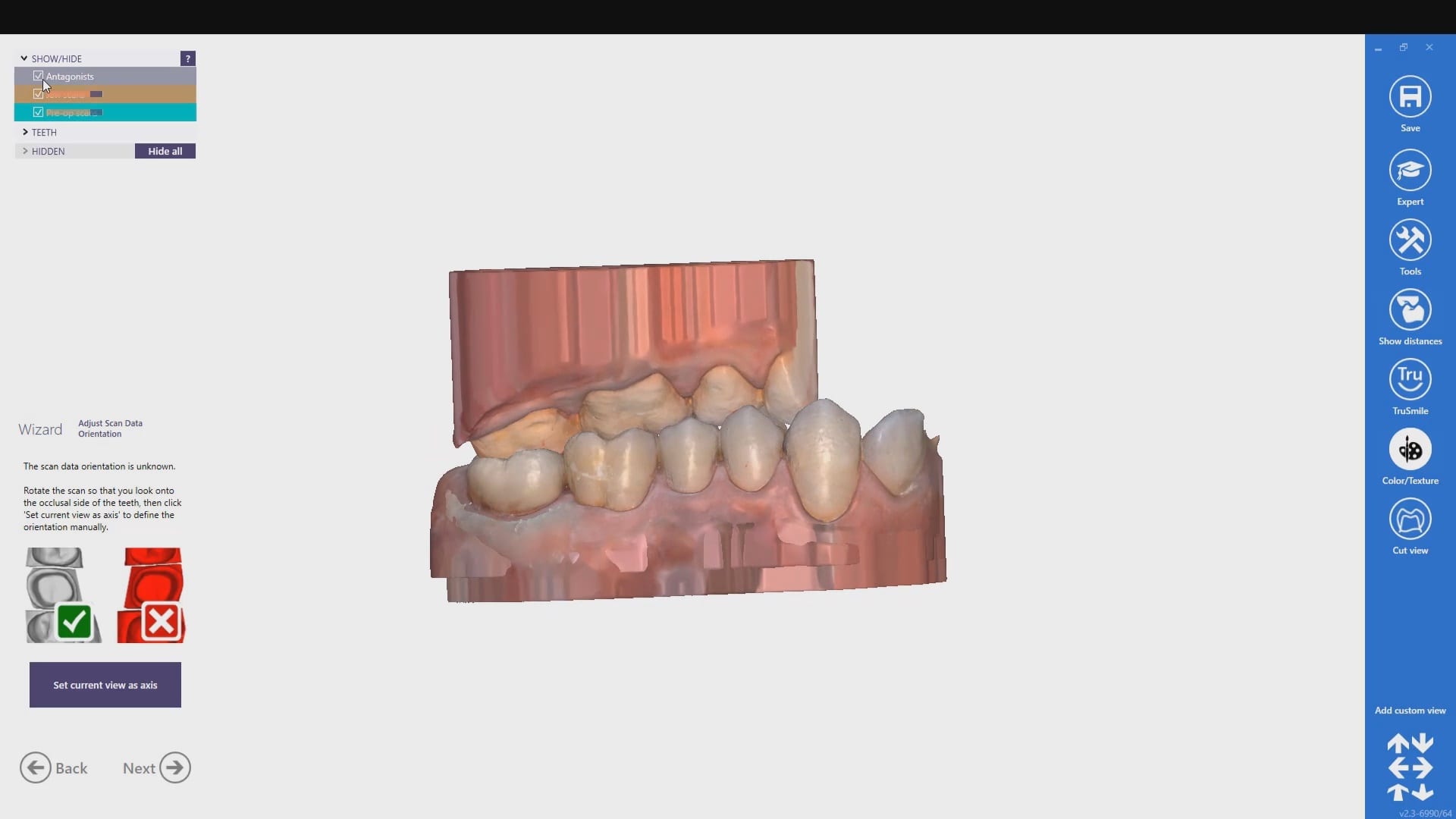
The traditional approach to these cases required a model of the arch with some suprastructure that could be used to relate it to the photogrammetry scan. This process can be quite arduous and involves lots of steps. Other current systems, like the Shining Elite allow you to merge models in the native scanning software. Alternatively, you must make sure you have common stitching abutments to related models to each other in CAD software. You can use common landmarks that are found in both models to accomplish this like in this demonstration
Managing Surgical Cases Where Stitching Landmarks are Removed to Accommodate Space for the Prosthesis
The approach to these get much more complicated when you don’t have those landmarks available to you from one model to the next, usually because the they have been surgically removed. You must:
- Capture the pre-op or wax up and relate it to the tissue scan
- capture the tissue scan and relate it to the implant location models.
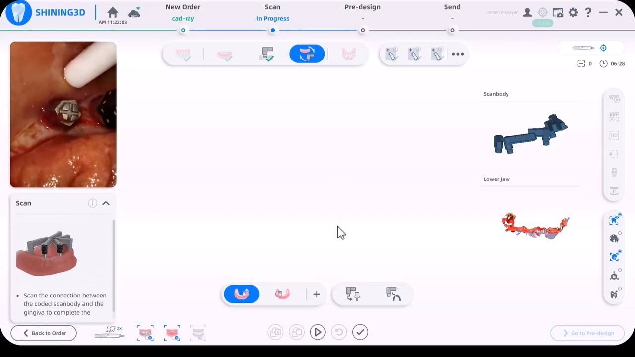
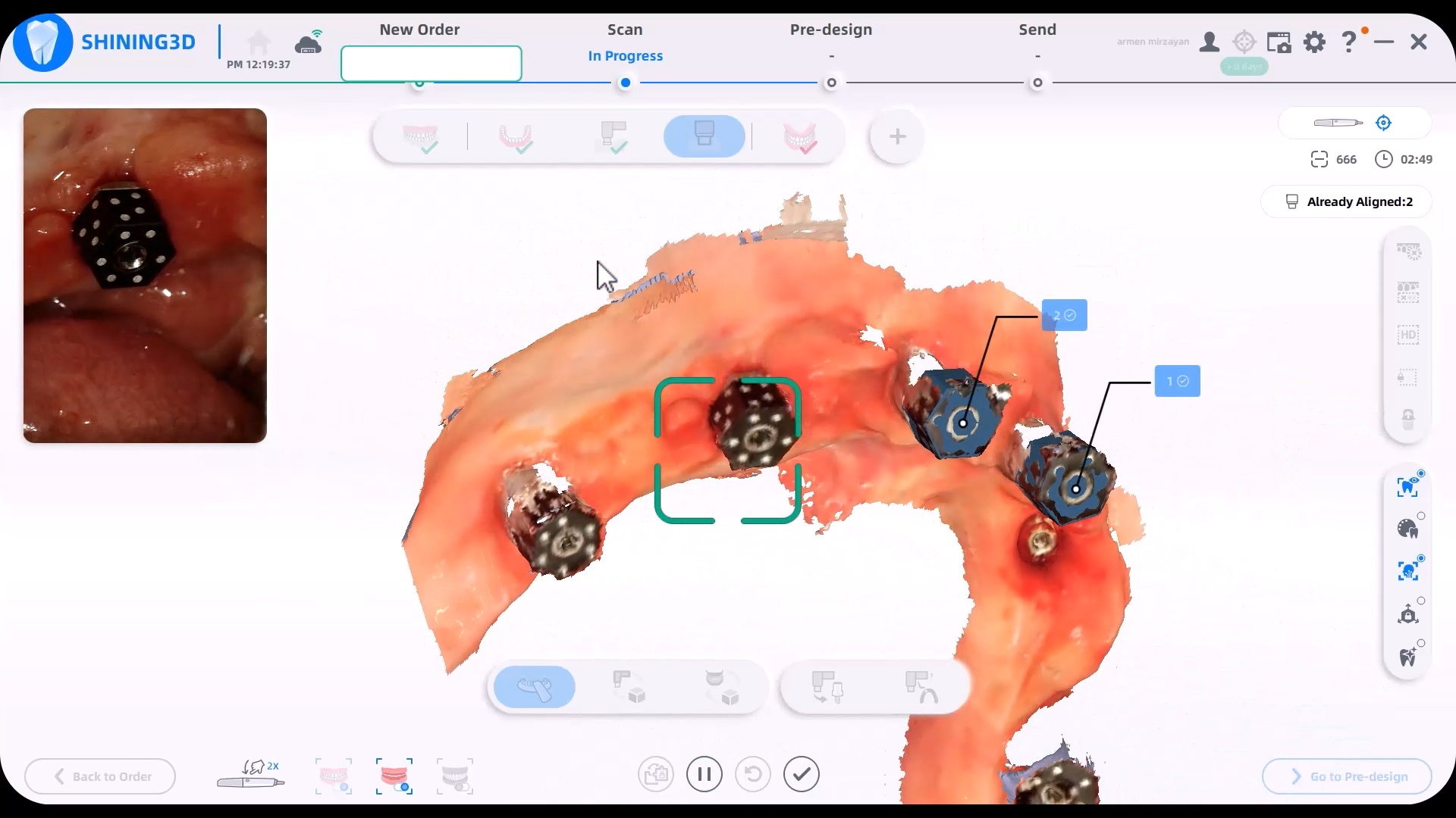
One way to do this is to place arch trackers in areas away from the crucial areas of the arch, namely the retromolar pad area on buccal to the mental foramen. The Shining Elite Scanner allows you to do this in their own native imaging software. In the first video you will see how the arch tracker allows you to relate the iPG scans with your tissue scans.
You have to leave the arch tracker in place from the very beginning to the very end. If possible, we recommend you remove them only after you have placed the temporaries as it leaves you a back up in case something goes awry in the process. You will use it to relate the preop to the tissue to the iPG models.
Scanbody vs Scancap for the Shining Elite Device
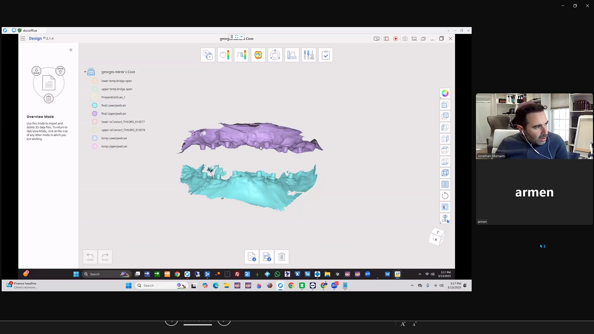
Alternate methods include using proprietary material from sources that are very well versed in this matter, like Jonathan Abeneim’s Excel Protocol, which he highlights in this webinar. He used his THS caps to not only related these models to each other but also perfectly mount your models to the opposing arch

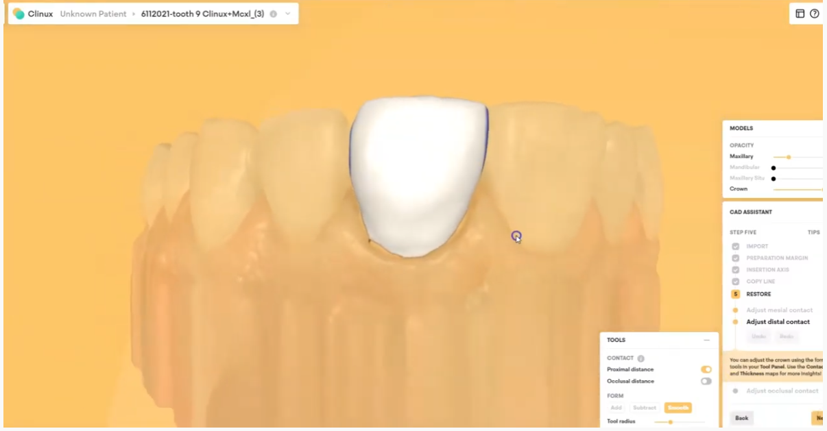


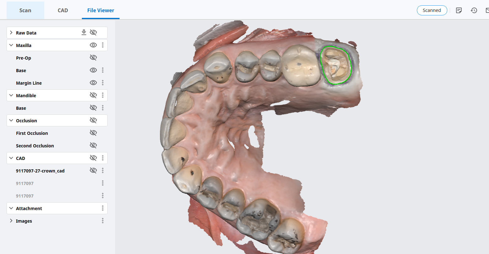
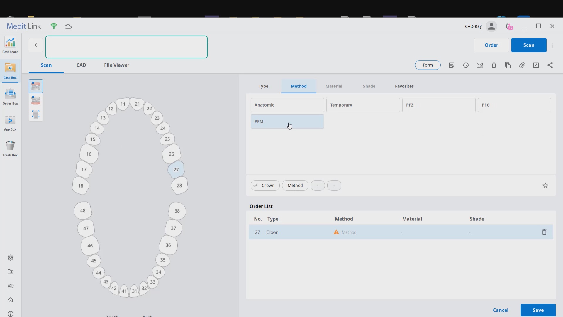
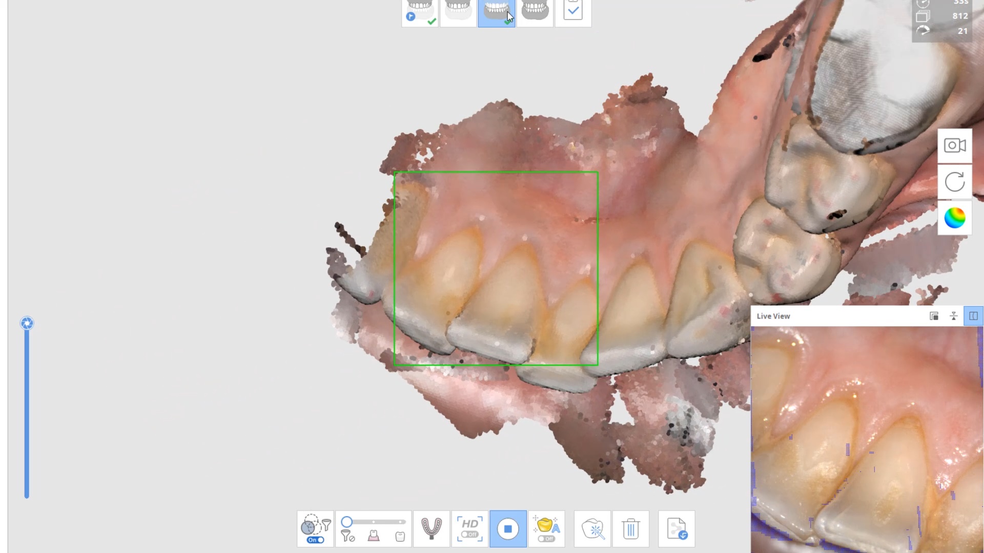
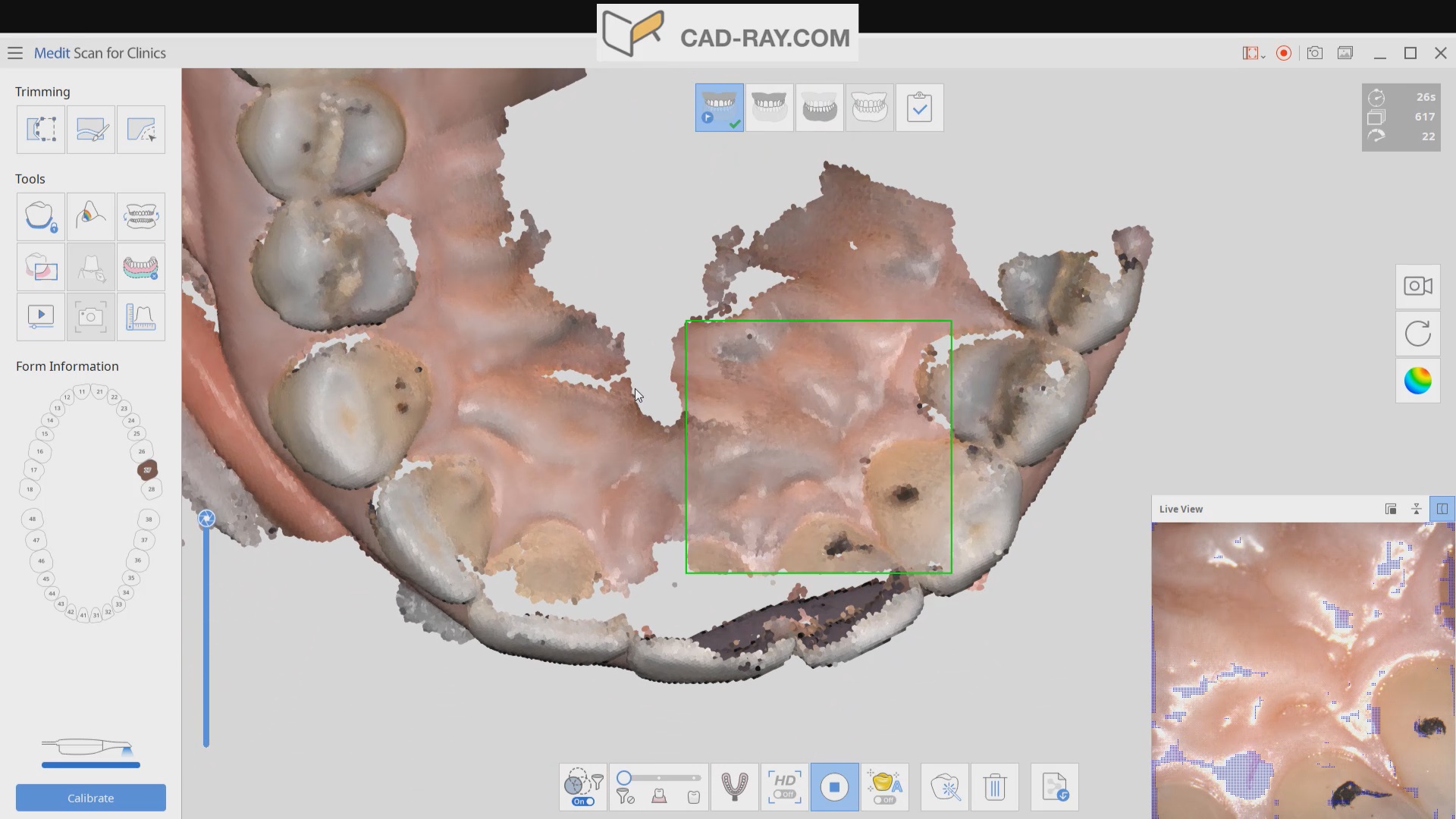
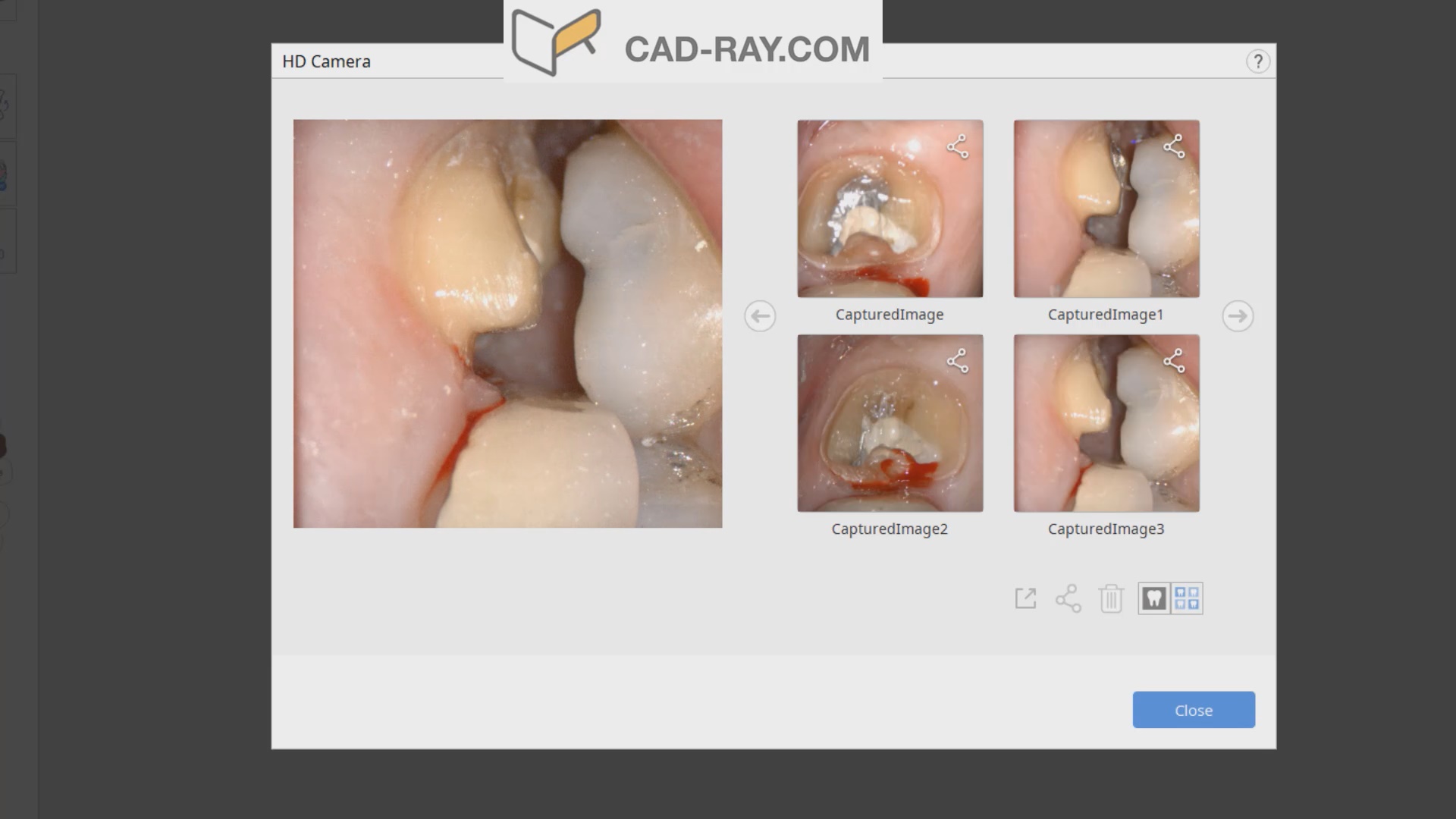
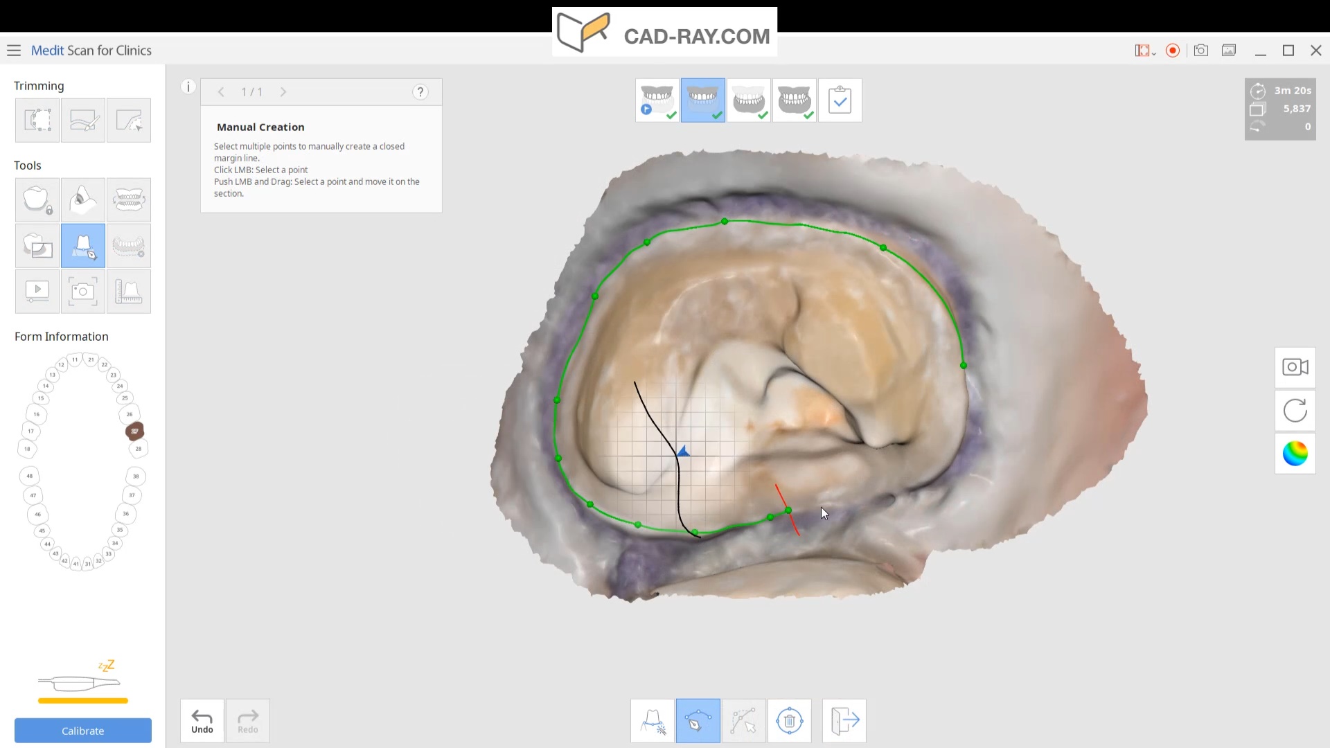
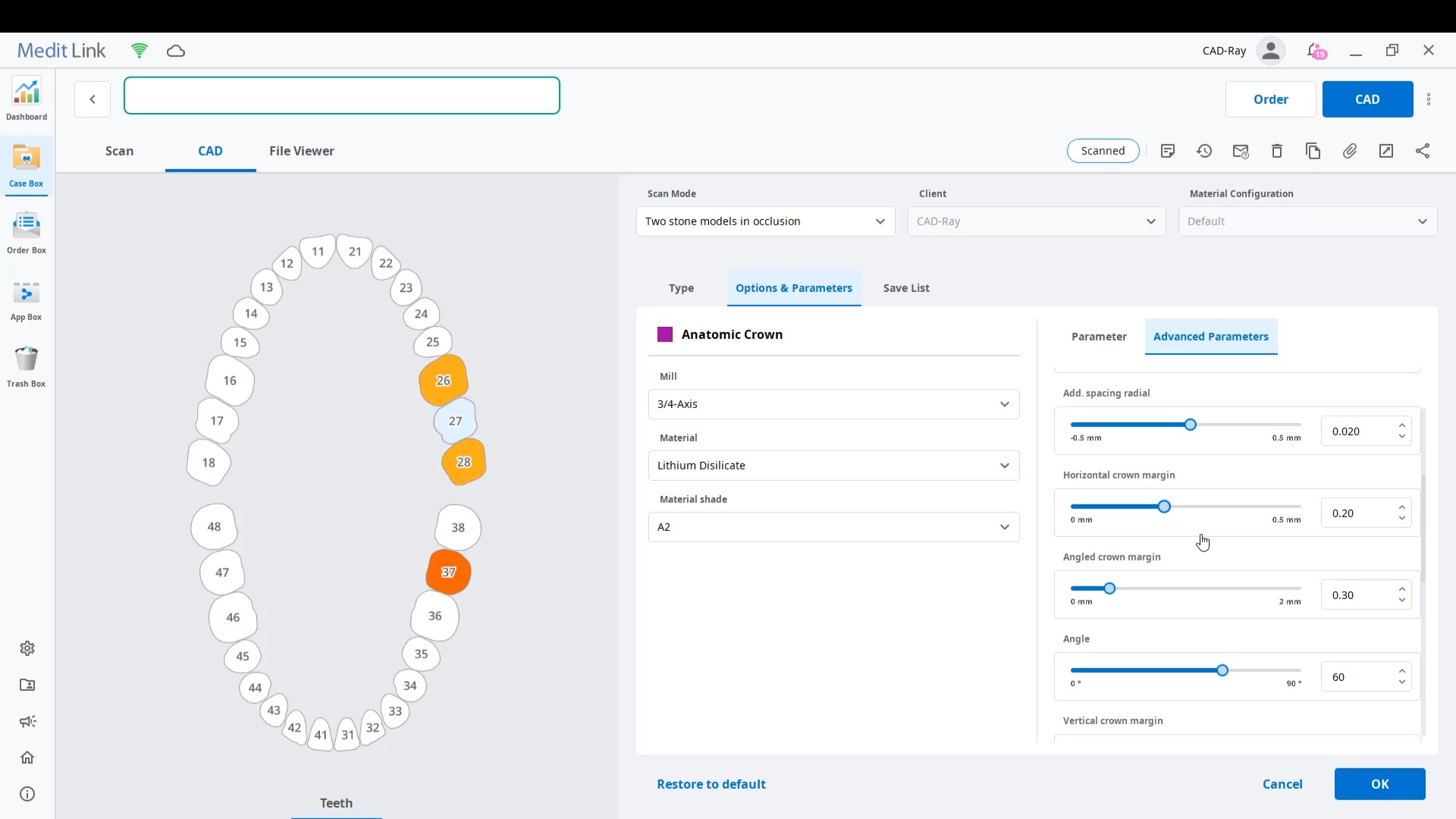
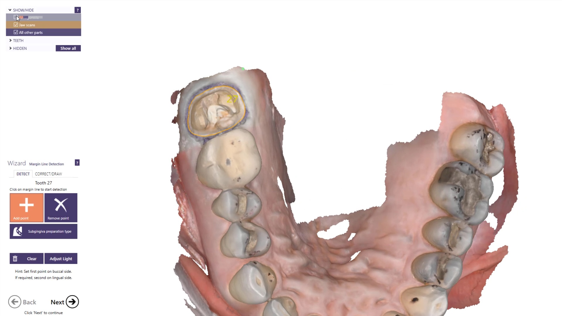

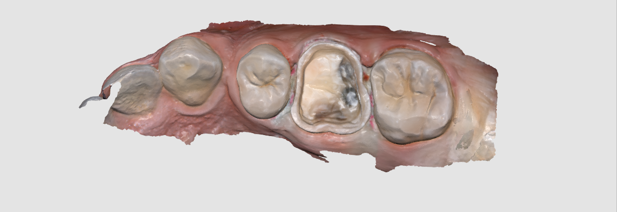
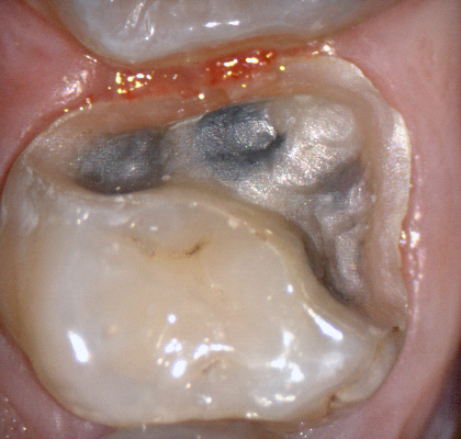
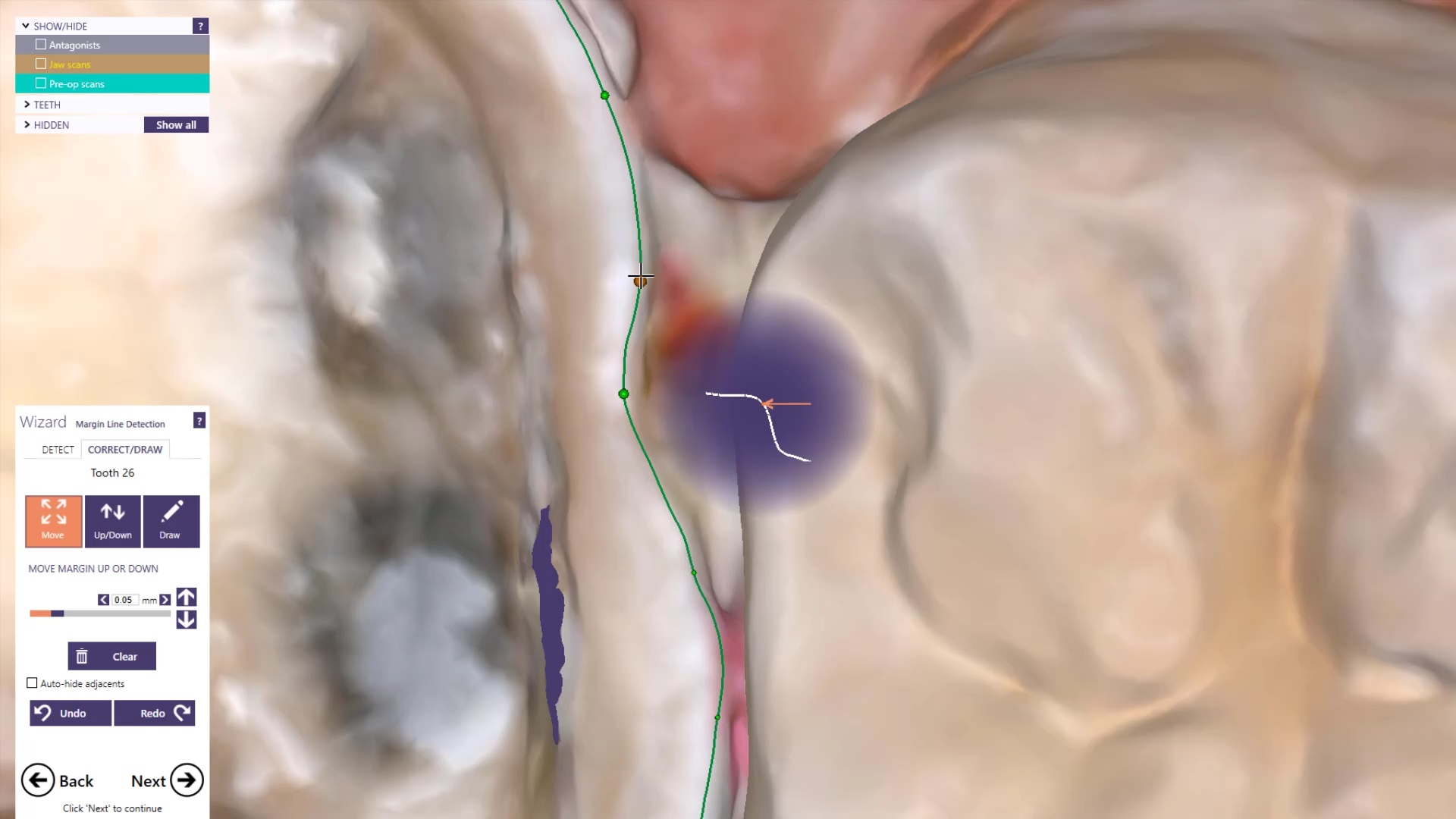

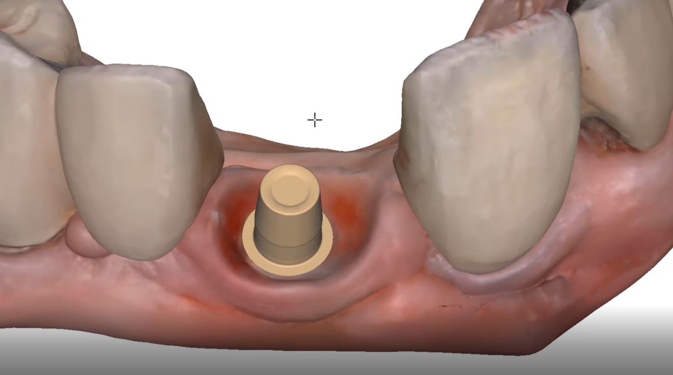
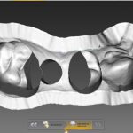


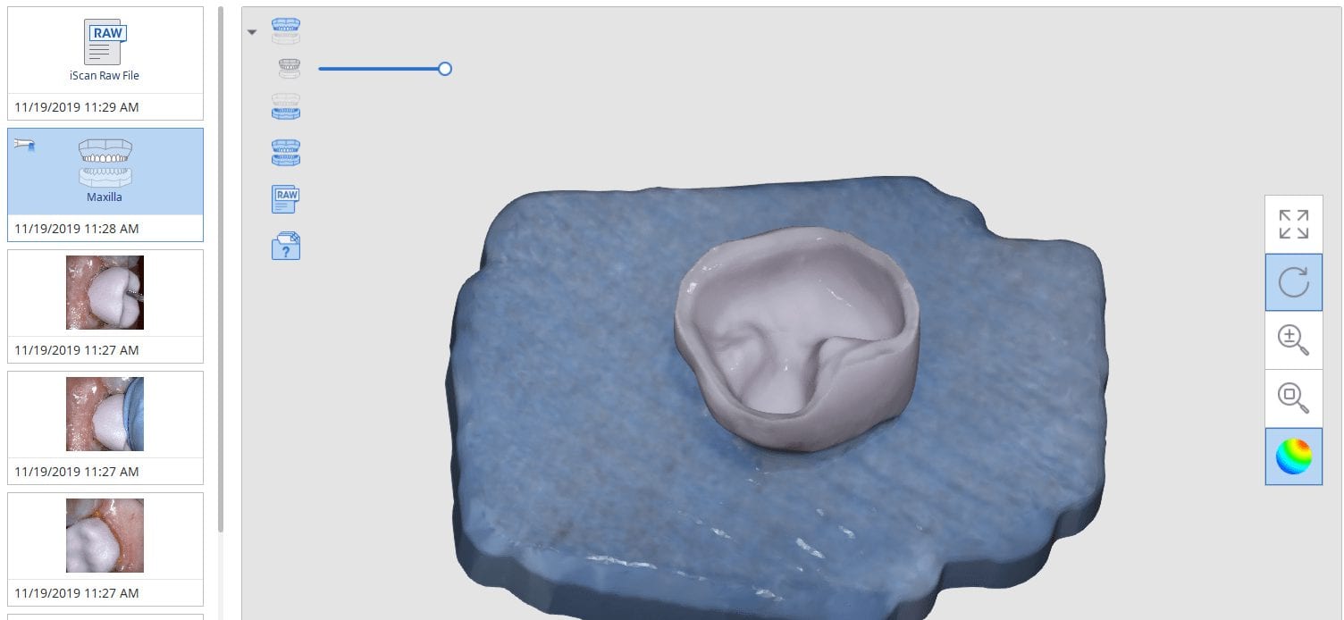


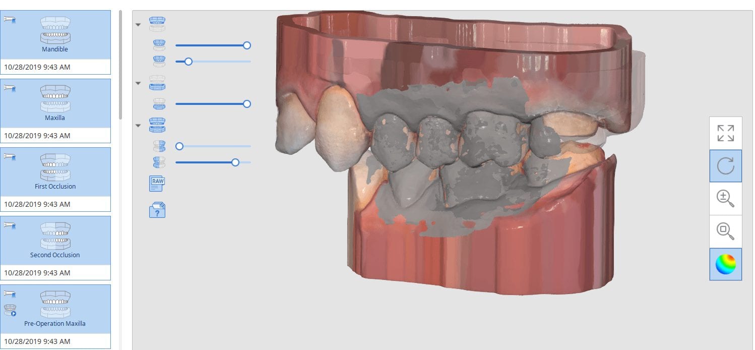
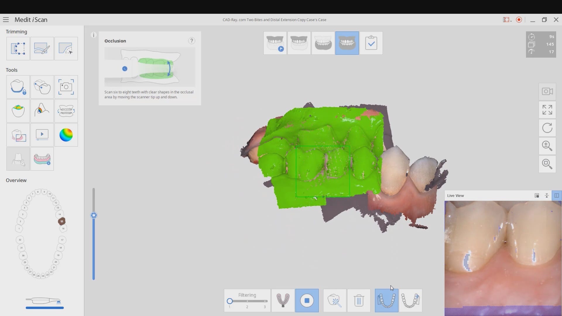

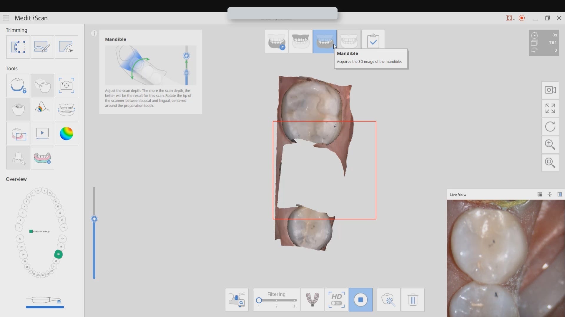
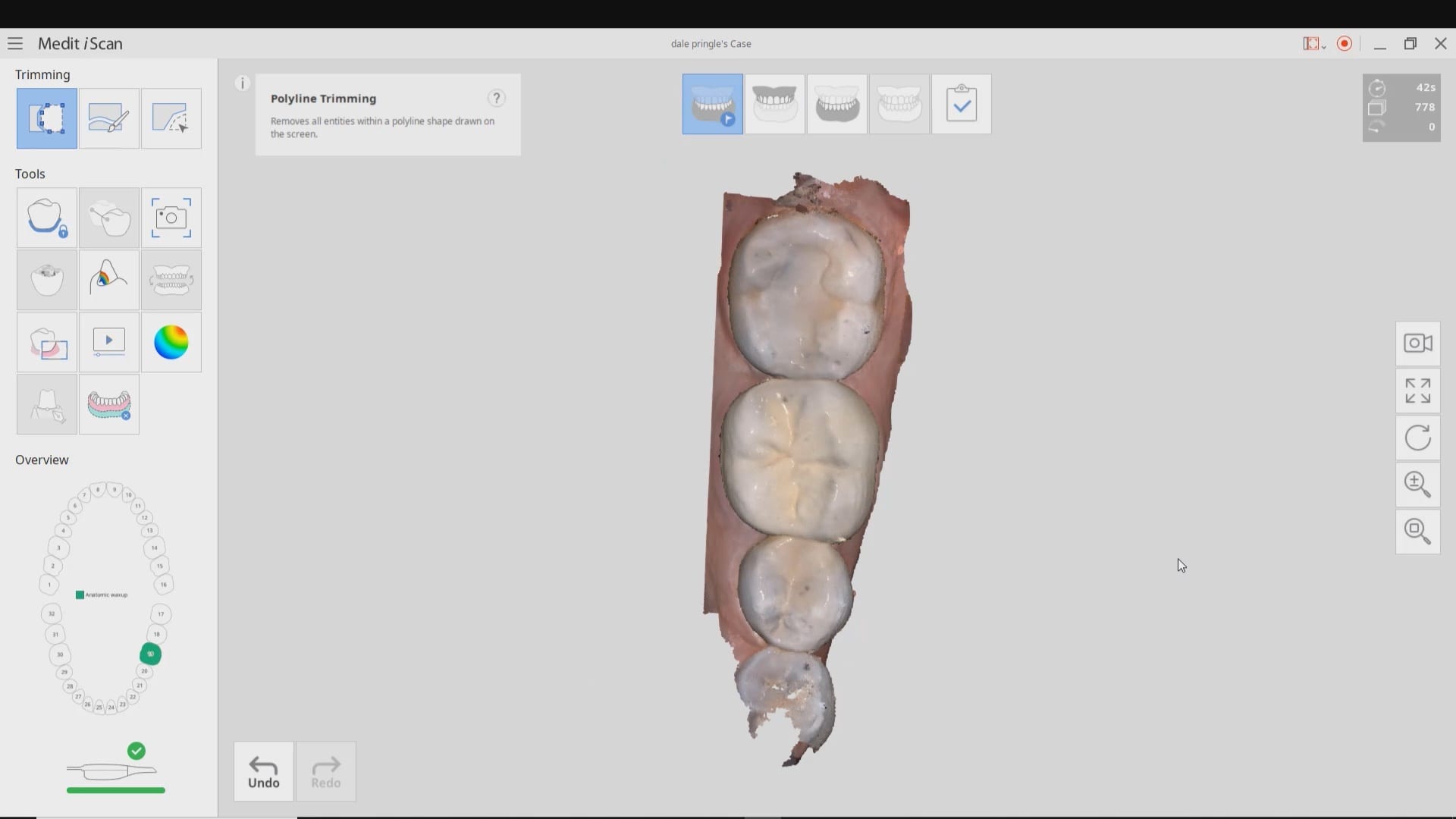

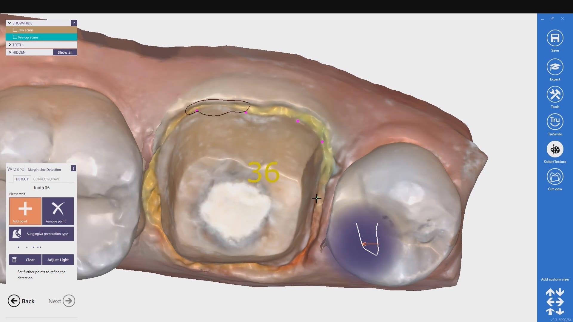

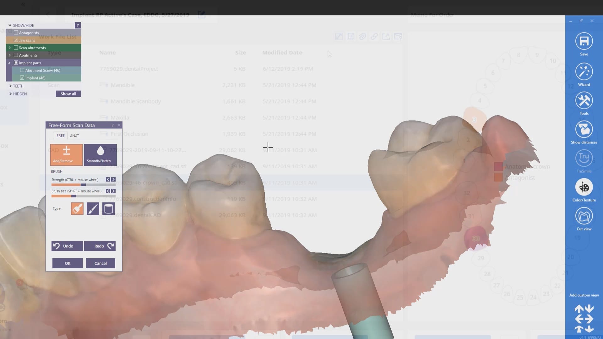
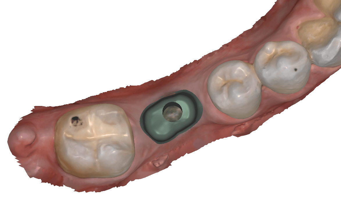

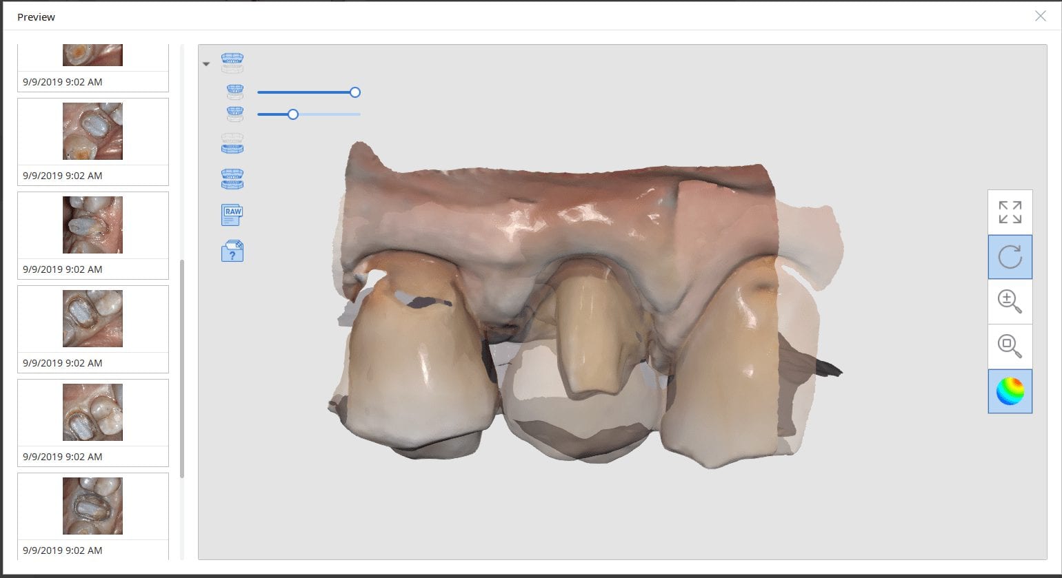
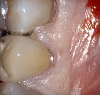
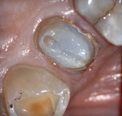
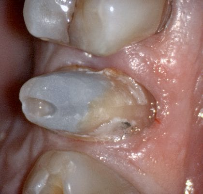
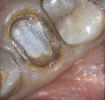
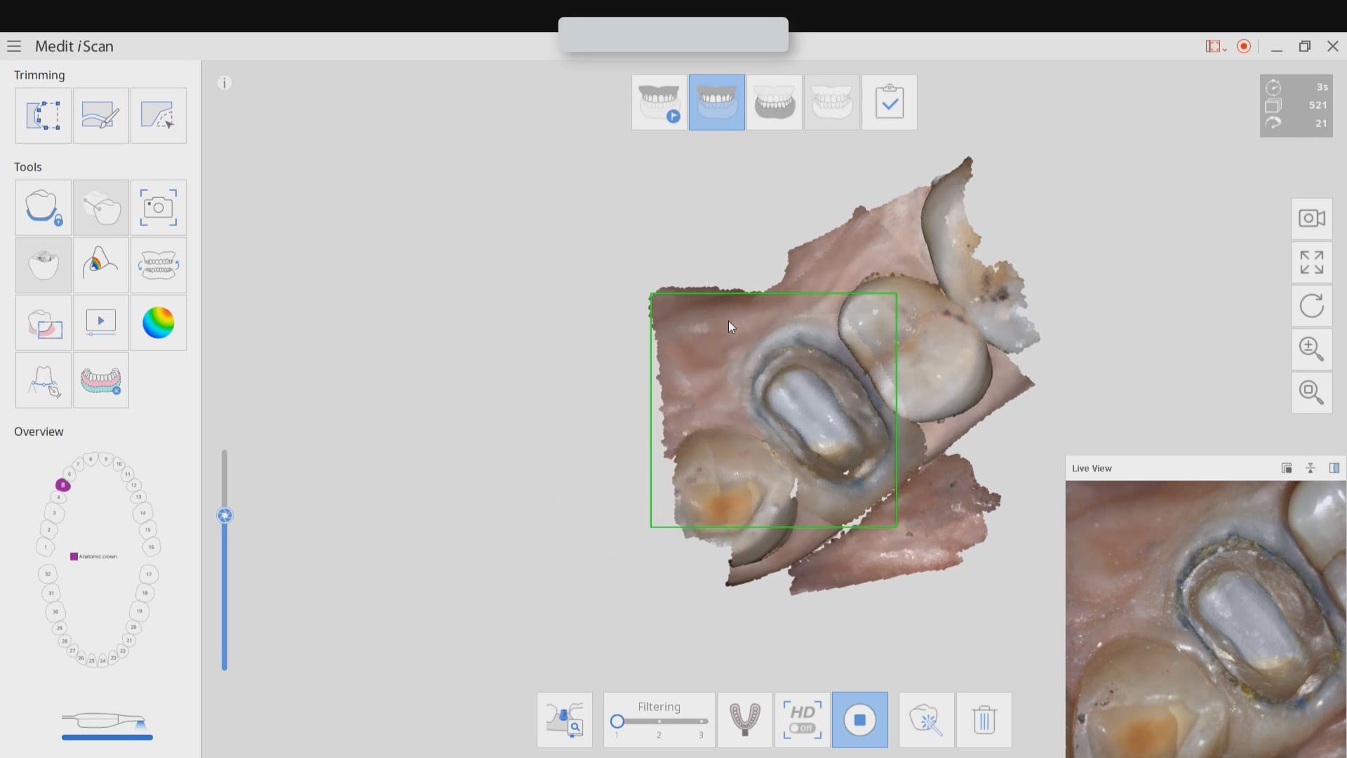
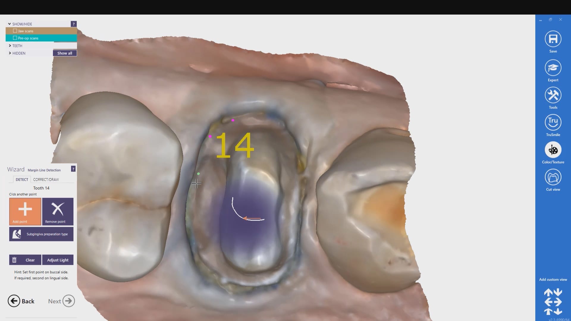


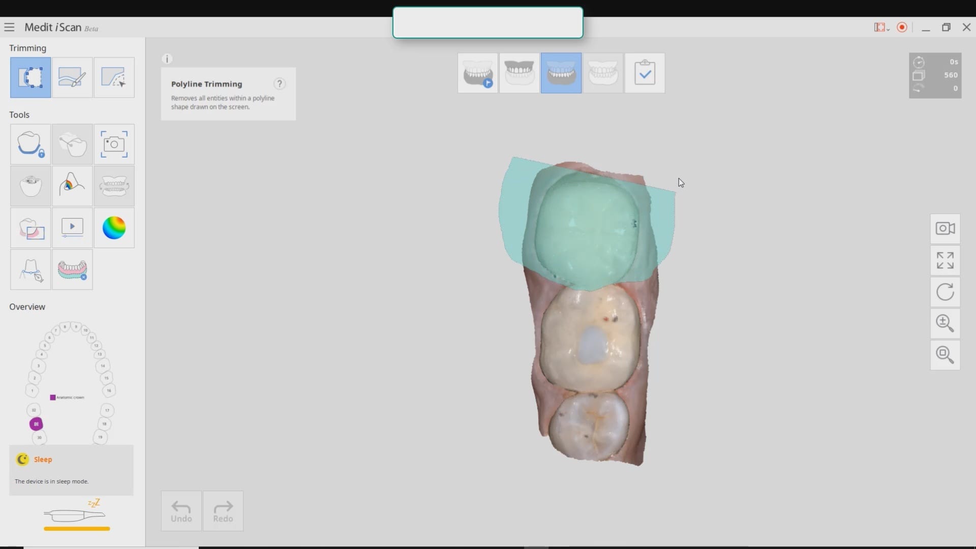
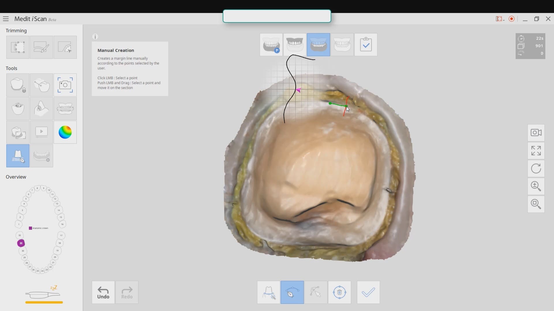
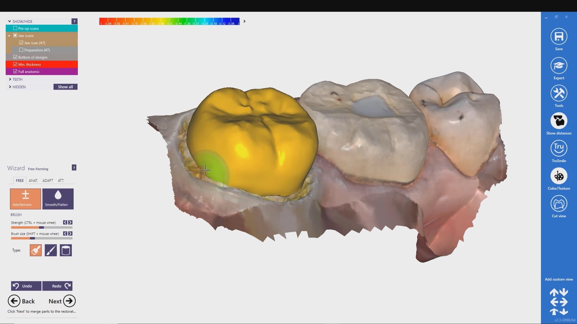
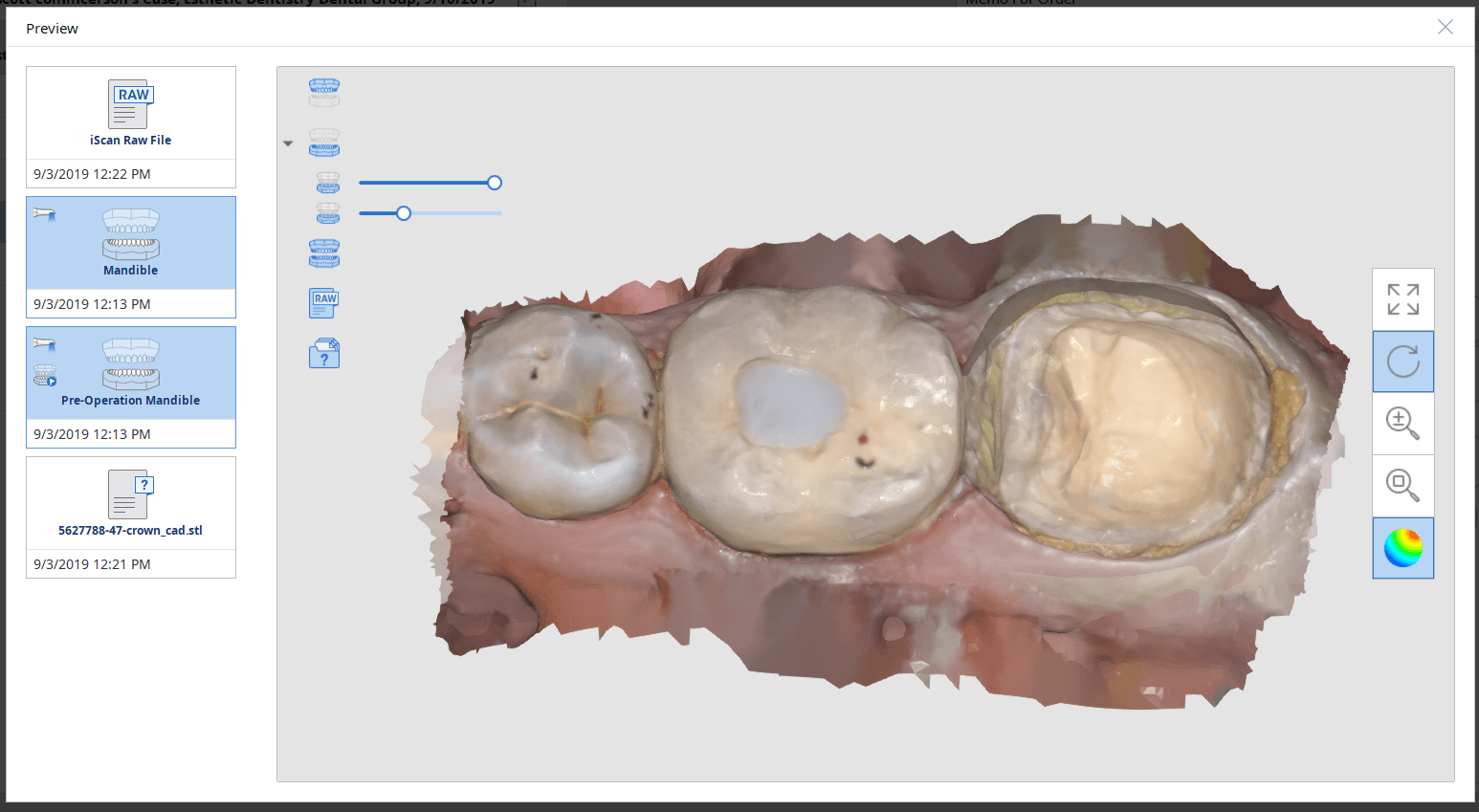

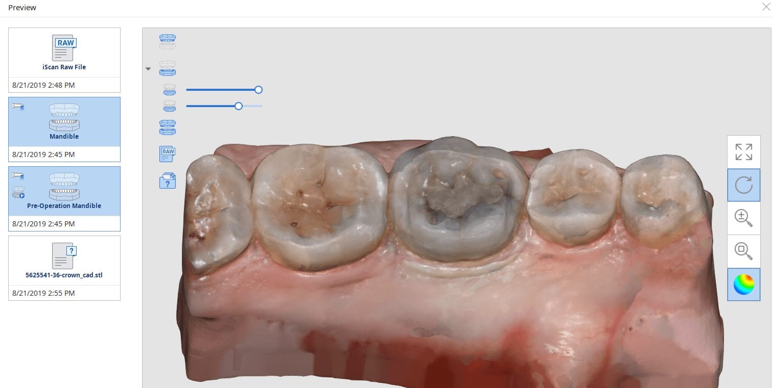
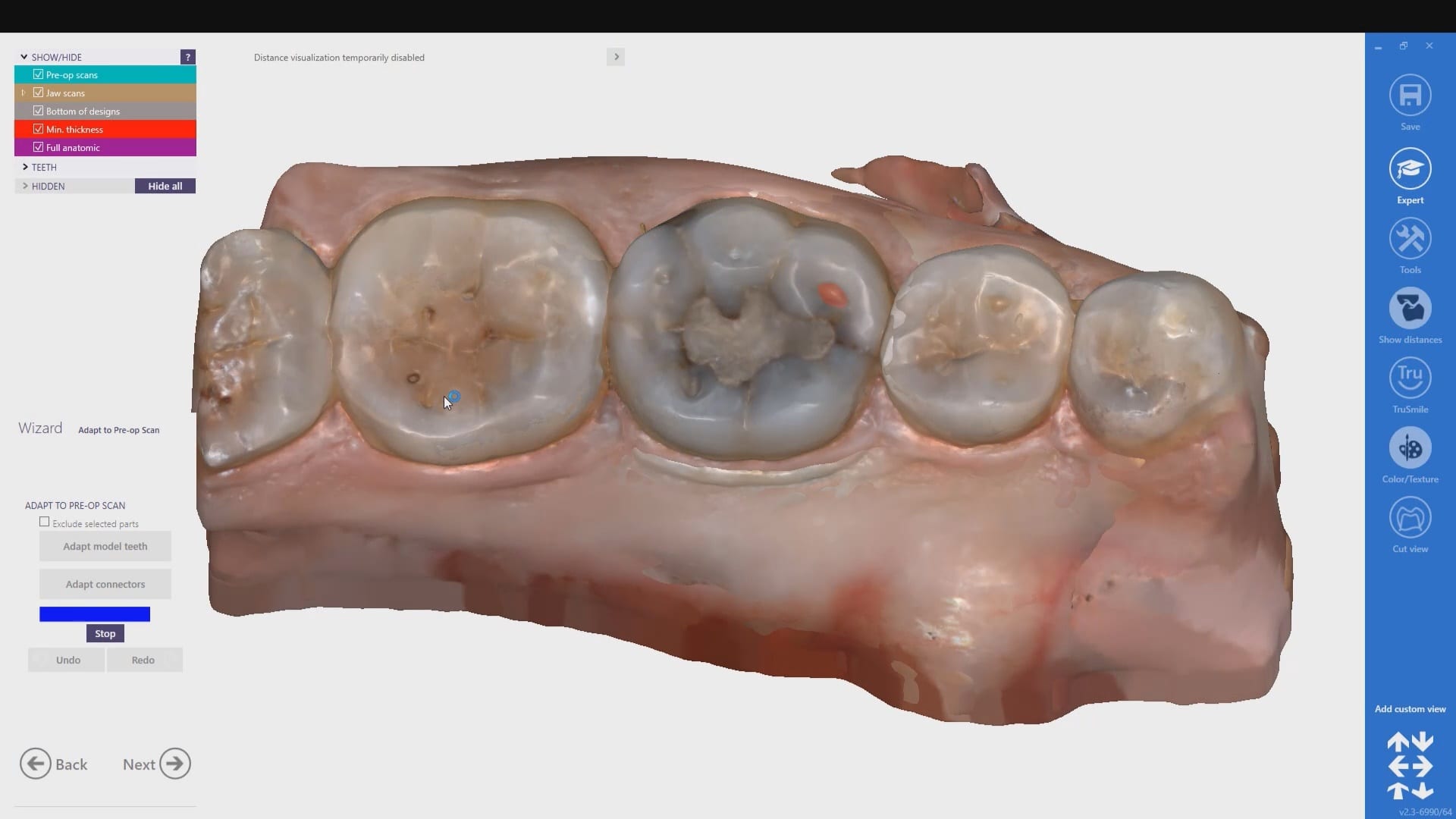

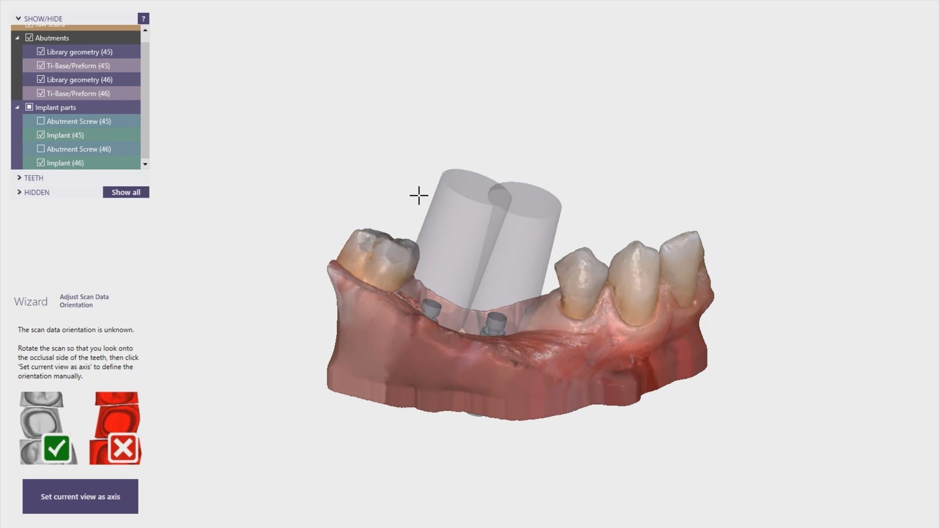

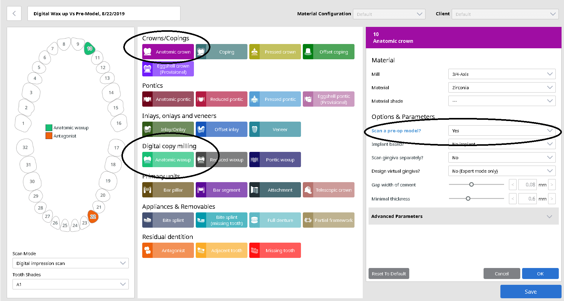
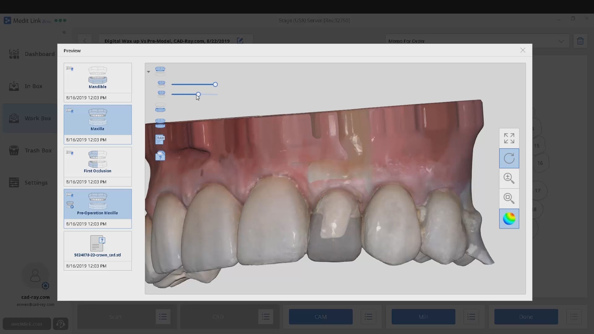
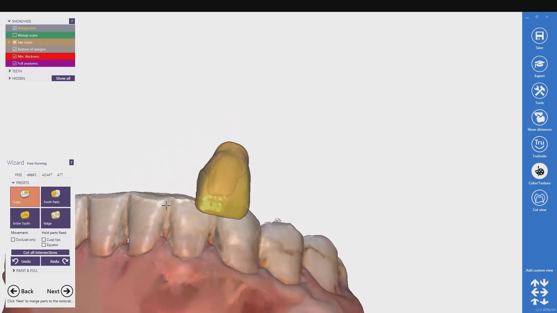

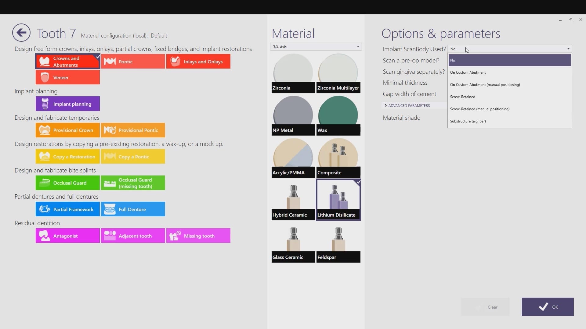
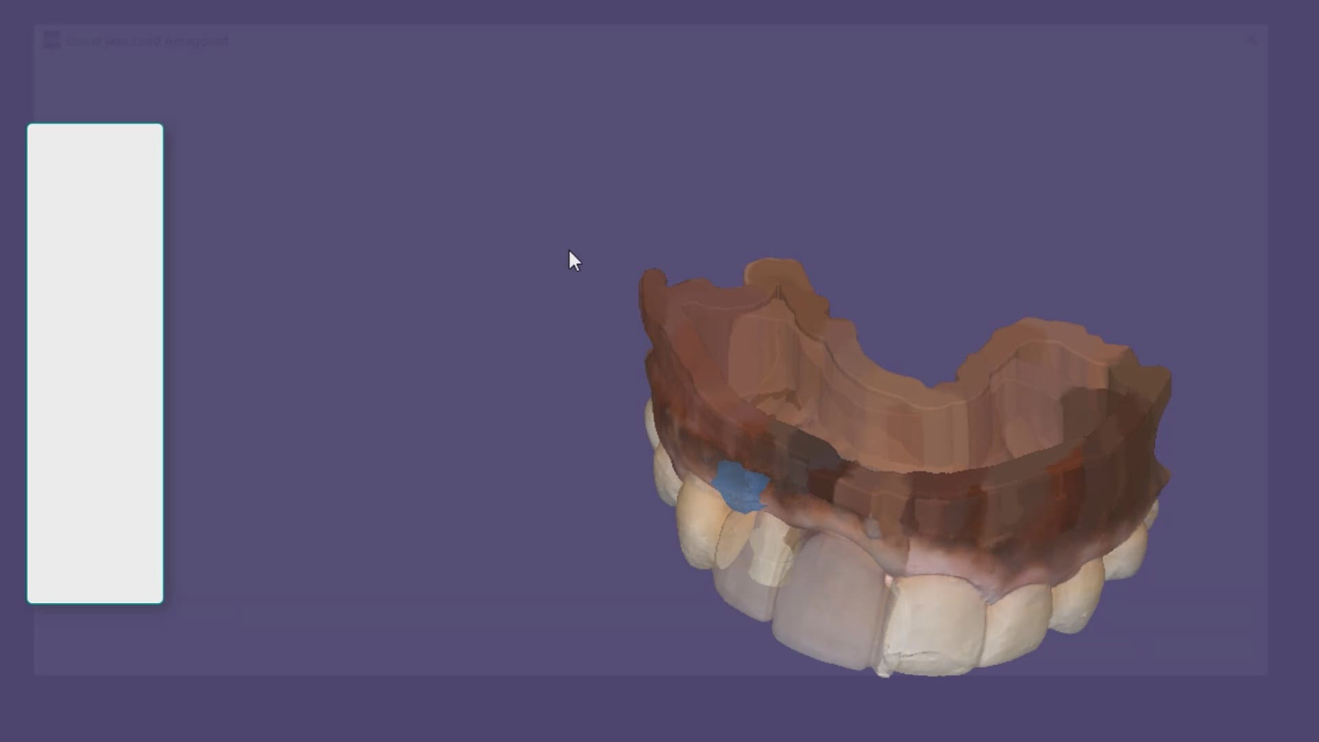
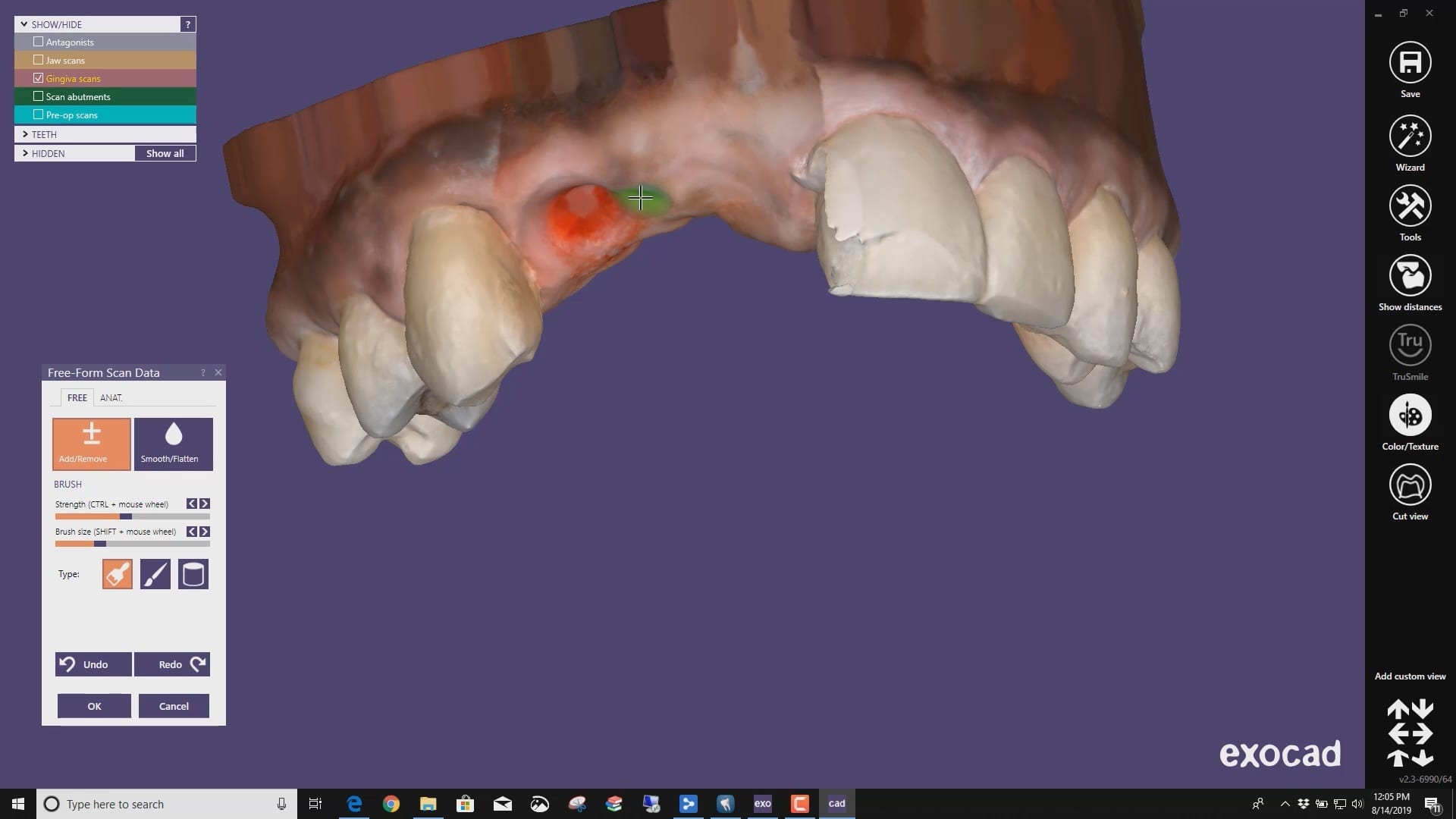
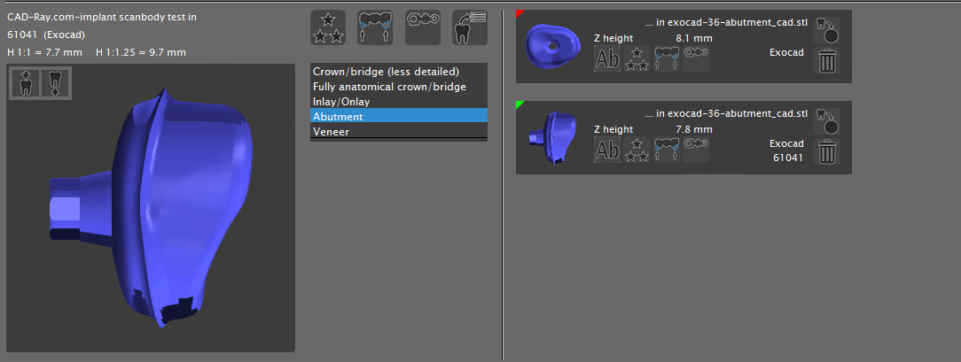
 A very common source of frustration for most dentists or those who are new to designing implant crowns is the emergence profile of the abutment or crown. Most of the time, the shape of the tissue dictates the digital design and this article showcases how we used the medit i500 for the intra-oral scan of the patient and then used exocad to design the restorations. Our advanced users can appreciate how we bring the arch model in twice- once as the maxillary model and once as the gingiva model. We then digital sculpt the tissue to create the proper profile yet we still have the original model to reflect back to asses the changes.
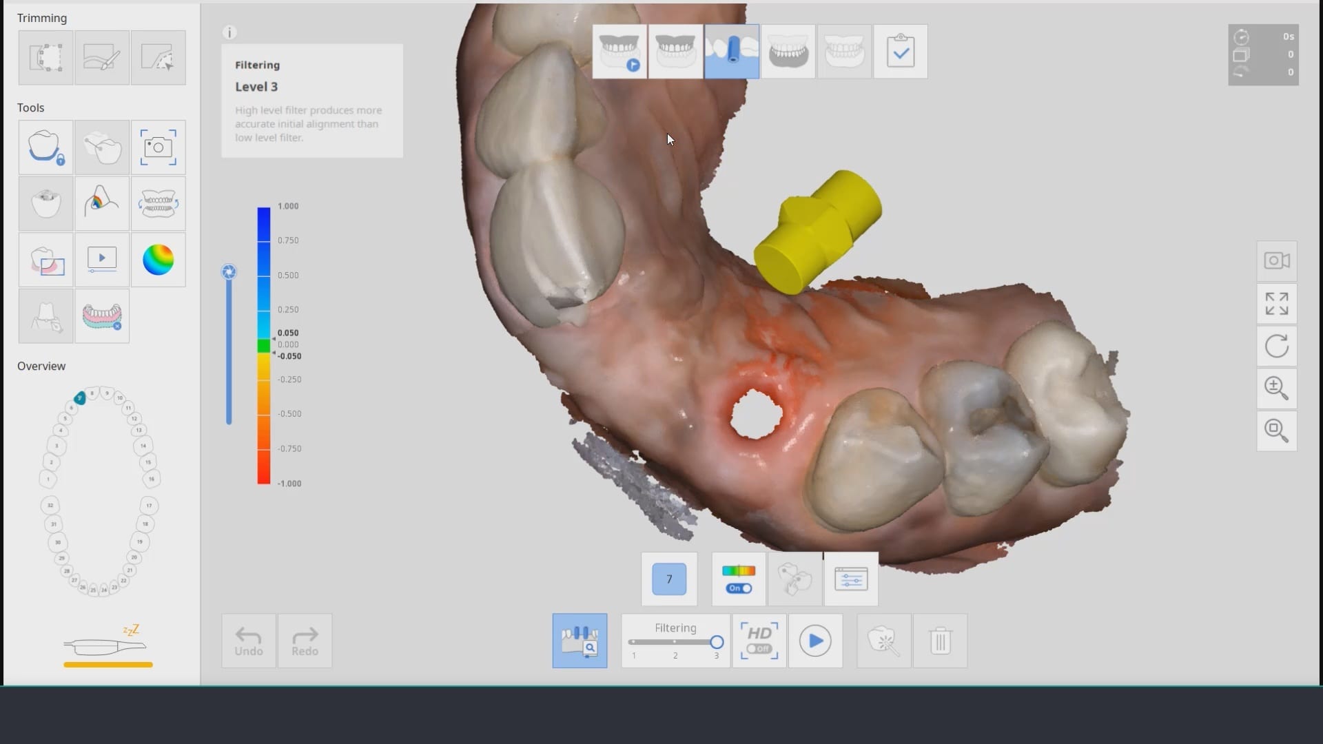


You must be logged in to post a comment.