I purchased a Medit Scanner from Cad Ray and the entire experience has been phenomenal. Their customer service is top notch and always accessible by text! I have FaceTimed Frank more than once during a hectic day to help me with my scanner. Thanks te...read moreI purchased a Medit Scanner from Cad Ray and the entire experience has been phenomenal. Their customer service is top notch and always accessible by text! I have FaceTimed Frank more than once during a hectic day to help me with my scanner. Thanks team!read less - 6/19/2020
Scot White
It's rare to find a company that actually has its customer's best interests in mind. They took all the intimidation out of the equation for me as I took the leap into the "digital dentistry." Frank Weinstein is the right person to know if you are try...read moreIt's rare to find a company that actually has its customer's best interests in mind. They took all the intimidation out of the equation for me as I took the leap into the "digital dentistry." Frank Weinstein is the right person to know if you are trying to learn about and buy and use digital tools in your office. It's so mush easier when you have knowledgeable people who are really on your side.read less - 7/07/2021
Norman Knowles
I have had the original iTero, a Trios 3, and a Carestream CS3600. A staff member broke the lens on the Trios and while waiting 3 weeks for an RMA to send it to Poland for six weeks to get it repaired, Carestream was sniffing around and suggested tha...read moreI have had the original iTero, a Trios 3, and a Carestream CS3600. A staff member broke the lens on the Trios and while waiting 3 weeks for an RMA to send it to Poland for six weeks to get it repaired, Carestream was sniffing around and suggested that I trade in my Trios so I did which began a 4 month nightmare with their piece of junk scanner. Absolutely awful customer service from both 3Shape and Carestream. I needed a scanner and had heard great things about it the Medit i500 at the Florida Academy of Coesmetic Dentistry so I got one. It works really well and Medit keeps adding new and useful features and their architecture is completely open. Two weeks ago, my i500 died so I contacted Cad-Ray surrport and I had a new unit in my office 24 hours later! That's absolutely unheard of in the industry!!! Both Cad-Ray and Medit have positioned themselves to be industry giant killers and they're doing it. The i500 is a phenomenal scanner at a phenomenal price point and service and guidance at Cad-Ray is just plain excellent.If you are thinking about getting a scanner, do it! Just contact Cad-Ray and go for it. You will only be happy about your purchase! Highly recommended!read less - 3/09/2021
Alex Vo
Great service and scanner support! Company delivers well above my expectations! Love my medit scanner. - 1/29/2023
Ramin Goshtasbi
Great service even if you own a Primescan. Company is built on customer service. Thanks for the help guys…. - 1/05/2022
Suresh Goel
CAD-Ray is a great resource for all things digital. Knowledgeable team but also able to anticipate your needs and because they’ve done it so many times they seem to know what you need before you do! Definitely the first place to look for digital ha...read moreCAD-Ray is a great resource for all things digital. Knowledgeable team but also able to anticipate your needs and because they’ve done it so many times they seem to know what you need before you do! Definitely the first place to look for digital hardware and integration!read less - 6/16/2020
Robert Crosby
The i700 is the second scanner I have purchased. It is hands down far superior in terms of quality and ease of use than my first scanner (3M Tru Def). I was hesitant to enter the market again but wanted to mainly for implant reasons. After talking...read moreThe i700 is the second scanner I have purchased. It is hands down far superior in terms of quality and ease of use than my first scanner (3M Tru Def). I was hesitant to enter the market again but wanted to mainly for implant reasons. After talking with Laura and watching her presentation with my staff, we were sold! The i700 was extremely reasonable in price while being similar to units costing twice as much. CAD-Ray made this possible. I found their on line training to be adequate in learning the necessary skills to start scanning, I continue to watch these videos as I sharpen my skills. Initially I was concerned about the on line training. But now I actually prefer this way of training as it is self paced and you always have the library of videos to watch when needed. Laura has been there to answer questions and help me whenever needed and I’m talking on nights and weekends too! I admit I was was extremely hesitant to get another scanner, especially with an online outfit; but I have no regrets and highly recommend CAD-Ray and Laura for anyone needing a scanner! They provide excellent services.read less - 4/23/2022
Abhinav Bhatnagar
We have been using the scanner for a few weeks now. It’s been a blast to use and they have made it easy to learn with video tutorials. We have yet to go to the training, but we are excited to continue learning and expanding our digital dentistry. - 6/19/2020
Archstone Weatherford
Medit i700 intraoral scanner is the first scanner that I actually used on my patients. Before I put my hands on it, I had some prejudices against all scanners. They were bulky, laggy in capturing the images, etc. When I finally had the chance to use ...read moreMedit i700 intraoral scanner is the first scanner that I actually used on my patients. Before I put my hands on it, I had some prejudices against all scanners. They were bulky, laggy in capturing the images, etc. When I finally had the chance to use an intraoral scanner and get introductory training with Laura from CAD-RAY a few weeks ago, I totally changed my view of this product. Very soon, I was able to scan crown, bridge, and even denture cases. Of course, I have had some knowledge about the digital scanner from CEs provided in the past, but being able to apply it in the daily practice in such a short time was beyond my expectations. I would highly recommend MEDIT i700 and training from CAD-RAY.
Big thanks to Laura!
-Lei Fu, D.D.S.read less - 9/12/2021
Just got this scanner a few weeks ago. Has changed my workflow. Easy scanner to use. What's truly great is the support behind the product. Whether by call or fb messenger, I have never not been able to reach someone who solved the issue! Very pleas...read moreJust got this scanner a few weeks ago. Has changed my workflow. Easy scanner to use. What's truly great is the support behind the product. Whether by call or fb messenger, I have never not been able to reach someone who solved the issue! Very pleased so far.read less - 6/19/2020
Dr. Howard Lassin
Great 1st lesson with Ryan on the Mediti700. We are ready to scan:) - 12/30/2022
William Huszti
Nicely done Cad-Ray- Thanks for helping me get back to work! The new i700 is our tech fav! - 3/03/2022
Matt v
Matt Newman was excellent solving a cable problem.! Quick response and good follow up! - 9/11/2024
Maureen Copeland
Our office has been really happy with the i700 scanner so far. It was really easy to set up and use after watching only, 1-2 of the videos Cad-ray has on the website. Training with Andy was a breeze! Looking forward to taking level 2 training soon. - 1/20/2022
You guys are great! I have been a Cerec user for about a decade and wanted to expand my horizons. I bought the I700 and have just loved it. We don't do impressions any more, only scanning, even for the full arch. The customer service has been excelle...read moreYou guys are great! I have been a Cerec user for about a decade and wanted to expand my horizons. I bought the I700 and have just loved it. We don't do impressions any more, only scanning, even for the full arch. The customer service has been excellent, even though I haven't had any problems with the scanner. I really like the online learning modules, they have been awesome getting me up to speed with the scanner quickly. I am looking forward to some of the in person courses to maximize the usefulness of this scanner. -- Jeff Allred, DDS FAGD DABOI FAAIDread less - 9/28/2021
I bought a Medit 3 years ago and have had amazing success with both the scanner and the support from Cad-Ray. My scanner recently broke and They were on the phone with my assistant trying to fix the problem, and when it was unfixable, they overnight...read moreI bought a Medit 3 years ago and have had amazing success with both the scanner and the support from Cad-Ray. My scanner recently broke and They were on the phone with my assistant trying to fix the problem, and when it was unfixable, they overnighted a new scanner and helped us set it up. Medit is now available through many dealers, but I would only buy next one from Cad-Ray.read less - 11/03/2022
Kallen Wheeler
I always have enjoyed working with Cad-ray. Customer service is always on-point! - 5/25/2022
John T
Frank and the CAD-Ray crew are awesome! They are always available for support with the technology you purchase from them. - 1/25/2023
Jonathan Acker
Awesome people who care about their clients. - 7/09/2021
Varghese George
The customer service has been top notch, every single time. I have only good things to say about them. - 4/05/2022
Caroline Langlois
It's so nice to enter the digital age for scanning! I've been taking impressions since 1975. Medit i700 is amazing and our #1 supporter, Laura has been with us every step of the way. I truly don't know what I would do without Laura and Nick in tec...read moreIt's so nice to enter the digital age for scanning! I've been taking impressions since 1975. Medit i700 is amazing and our #1 supporter, Laura has been with us every step of the way. I truly don't know what I would do without Laura and Nick in tech support. They definitely need a raise! Yes, we had a couple of glitches (mostly operator error) but they were there with us all the way. The detail that the scan gives, whether it's a crown, bridge, full mouth scan for patient review and now many scans for NTI's is truly amazing! We recommend it highly to all who are interested! I am proof that as a dental assistant who's 64, you CAN teach an old dog new tricks!!!read less - 12/09/2021
Steven Polasek
The cad ray team is the best! Jon and Nick offer first class service! I ordered a medit i500 from another supplier and had to cancel my order after it had not arrived within 3 weeks. Placed my order with Jon and Nick, had the scanner to me within 24 ...read moreThe cad ray team is the best! Jon and Nick offer first class service! I ordered a medit i500 from another supplier and had to cancel my order after it had not arrived within 3 weeks. Placed my order with Jon and Nick, had the scanner to me within 24 hours of purchase. I love my medit! Best scanner on the market!read less - 6/15/2020
We’ve been using the Medit i700 in our office for approximately a year now. It has been a game changer and hard to remember what it’s like without using the intra-oral scanner. The Cad-Ray support team has been remarkable as well! - 9/11/2022
Barton Davis
Every time I need support for my scanner, the Cad-Ray team is there to help. I recently had a question on how to manipulate a scan and export it back to Medit Scan. Damien logged in and helped me out. Problem solved in under five minutes. Awesome ser...read moreEvery time I need support for my scanner, the Cad-Ray team is there to help. I recently had a question on how to manipulate a scan and export it back to Medit Scan. Damien logged in and helped me out. Problem solved in under five minutes. Awesome service. Thanks Cad-Ray support team!read less - 3/04/2022
Logan Riggs
I always rely on Frank to help with any questions or concerns regarding our printer. The best in tampa. - 1/25/2023
Rodney Baier
Cad ray has been very nice to work with. Excellence service and support since I bought my Medit scanner - 6/16/2020
Andy M
It has been great to work with Laura and Heather. The purchase, financing, shipping, and training process has been smooth. The training was very comprehensive and not rushed at all. I love my Medit i-600 scanner, and I recommend CAD-RAY 100%! - 5/22/2024
Yu Gan
Great company. Pioneer in digital dentistry. Armen knows his stuff. Hands down the go to scanner reseller in the US. Support and training courses are incredible. - 10/02/2022
Peipei Yu
I purchased a Medit scanner in August and I am very happy with the scanner. I was trained on an Omnicam in dental school and used Omnicam for 4 years in my associateship. The speed and quality of the Medit scanner is comparable to a CEREC scanner but...read moreI purchased a Medit scanner in August and I am very happy with the scanner. I was trained on an Omnicam in dental school and used Omnicam for 4 years in my associateship. The speed and quality of the Medit scanner is comparable to a CEREC scanner but you can’t beat the price of the Medit! I would highly recommend this if you are a beginner or pro in digital dentistry!read less - 9/21/2020
H C
I got my 3Dshape scanner, great support , my training with Destany was excellent. Great team!! - 2/15/2024
Mital Patel
Cad-ray has been awesome with support and training! I got the medit in 2018 and couldn’t imagine practicing without it! Armen and frank somehow seem to be available at all hours of the day, and I can typically have them remote in same day if I need a...read moreCad-ray has been awesome with support and training! I got the medit in 2018 and couldn’t imagine practicing without it! Armen and frank somehow seem to be available at all hours of the day, and I can typically have them remote in same day if I need any help.read less - 6/16/2020
Yordanka Ivanova
I had been on the market for a scanner for a while and the i700 is my first intraoral scanner purchase. We are still new to the scanning world and its capabilities. Frank DeLuca was my main contact from the beginning and the person who did our traini...read moreI had been on the market for a scanner for a while and the i700 is my first intraoral scanner purchase. We are still new to the scanning world and its capabilities. Frank DeLuca was my main contact from the beginning and the person who did our training. The scanner is incredible and has surpassed our expectations even though we haven’t used it to its full potential yet. Frank has been amazing and always there to guide us every step of the way. Having such fabulous customer service and support from CAD-Ray was key for us when making this purchase decision. Thank you!read less - 6/23/2022
Karam ALrousan
i purchased medit intraoral scanner a year ago, other than the scanner is great, the customer service is outstanding whenever j need help or have a question they are ready instantly to answer my questions, cant ask for better customer service. - 6/16/2020
Jim Ellis
I've only worked with this company for a short time but I have found them to be wonderful in every way. Call, emails, and texts are returned very quickly and the equipment that we have purchased works wonderfully. I would highly recommend. Dr Jim Ell...read moreI've only worked with this company for a short time but I have found them to be wonderful in every way. Call, emails, and texts are returned very quickly and the equipment that we have purchased works wonderfully. I would highly recommend. Dr Jim Ellisread less - 5/12/2020
Rafael Dimayuga
Have been chatting with the CADRAY group for at least a year now even though I did not buy anything from them. They are very receptive, prompt and helpful. Finally bit the bullet and received my Medit yesterday! Now my Bluecam has a new buddy!! - 7/17/2020
Diana Teverbaugh
What can I say ! I have been extremely pleased with my scanner ! I recommend it to all my colleagues ! The support is the best , I bought the extended warranty and my scanner hada small crack and within one day they shipped my a new one ! I can’t wo...read moreWhat can I say ! I have been extremely pleased with my scanner ! I recommend it to all my colleagues ! The support is the best , I bought the extended warranty and my scanner hada small crack and within one day they shipped my a new one ! I can’t work without it ! Thank you !read less - 2/09/2022
Ellen Huang
Armen created series of these very helpful videos. They helped us tremendously in breaking into the new scanner we purchased. No matter you just got into digital dentistry or you are quite experienced with different fields of data acquiring or treatm...read moreArmen created series of these very helpful videos. They helped us tremendously in breaking into the new scanner we purchased. No matter you just got into digital dentistry or you are quite experienced with different fields of data acquiring or treatment planning, you will find those being tremendous help.read less - 5/24/2020
I just bought my first Intra-oral scanner (Medit I-700). I have demoed scanners from various companies in the past but have been less then thrilled with the applications, scanner ability, ease of use and overall user experience. I feel that now the...read moreI just bought my first Intra-oral scanner (Medit I-700). I have demoed scanners from various companies in the past but have been less then thrilled with the applications, scanner ability, ease of use and overall user experience. I feel that now the technology has caught up to where it should be and after reviewing many scanners on the market have decided to go with Medit. The Medit i-700 gives me all the functionality I could want, has an affordable price and works for all the procedures I need it for (scanning for ortho, dentures, partials, crowns, bridges, implants ect.). I love that they continually update their software and most importantly that those upgrades are free to the end users. Another huge plus is that when I have a question I get actually get someone on the phone!! For all these reasons I finally jumped in. I would recommend anyone else to do so as well!read less - 5/06/2021
Ajitha Gereddy
We purchased Medit i-500 with CAD ray last December and customer support is great.One of best thing for our practice is having intra oral scanner ,works great . Laura was very patient with our learning curve. - 12/10/2021
Engy Hassan
Amazing customer service! Excellent on time feedback. Thank you Kaila - 12/08/2021
Cody Boseman
Cad-ray has been amazing, not to mention they have an amazing product in the medit i500. Their training is great, customer service is quick and thorough, and follow up is consistent. I highly recommend using cad-ray for anything that you may need. - 6/19/2020
Carter Weber
I had a great experience with CAD RAY. I was lucky enough to have Frank DeLuca come down to my office to demo the Medit I700. Needless to say, we were in love with the technology and the great hands on demo. CAD RAY overnighted me the scanner and we ...read moreI had a great experience with CAD RAY. I was lucky enough to have Frank DeLuca come down to my office to demo the Medit I700. Needless to say, we were in love with the technology and the great hands on demo. CAD RAY overnighted me the scanner and we were off to the races. Any time we have had a technical question, Frank has personal helped me or put me in touch with one of his colleagues if he wasn’t available. All around, it was as 5 star experience!read less - 12/16/2021
ryan ku
I've been using this for almost 2 months now and I just love it. At this price point, ROI is a no-brainer. The convenience factor is amazing. I only did the DIY online training and I'm pretty confident doing the scan. I've signed up for the actual ...read moreI've been using this for almost 2 months now and I just love it. At this price point, ROI is a no-brainer. The convenience factor is amazing. I only did the DIY online training and I'm pretty confident doing the scan. I've signed up for the actual course so looking forward to seeing it's greater potentials.read less - 10/14/2019
New technology can be intimidating, but this i700 is user friendly and is everything you could ask for in regards to a great scanner. Cad-ray also made the transition easy and smooth. Customer support here is unreal. Telling all my dental buddies abo...read moreNew technology can be intimidating, but this i700 is user friendly and is everything you could ask for in regards to a great scanner. Cad-ray also made the transition easy and smooth. Customer support here is unreal. Telling all my dental buddies about these guys, and plan to make more purchases in the future.read less - 4/18/2022
Absolutely love Laura. She was my initial contact and is an amazing resource for any questions even months later. Would highly recommend buying from Cad Ray especially Laura! - 6/28/2022
Michael Martinsen
Honestly the best service that I've received in dental tech support. I had originally purchased a scanner with another supplier and was underwhelmed with the support I received. I switched over to CAD-Ray for my second scanner and have never been let...read moreHonestly the best service that I've received in dental tech support. I had originally purchased a scanner with another supplier and was underwhelmed with the support I received. I switched over to CAD-Ray for my second scanner and have never been let down. They are prompt and exceptionally knowledgeable about the products they support. Thank you CAD-Ray for keeping my practice moving smoothly!read less - 8/27/2021
Gwen Giannina
CAD-Ray is an amazing company. I purchased my scanner 3 years ago. Any small issue immediately resolved by calling them for help. I originally scanned with Cerec. The ROI doesn't even compare. The Medit was by far the best technology purchase of my ...read moreCAD-Ray is an amazing company. I purchased my scanner 3 years ago. Any small issue immediately resolved by calling them for help. I originally scanned with Cerec. The ROI doesn't even compare. The Medit was by far the best technology purchase of my 20 plus years in dentistry. I will upgrade at some point and will buy again from CAD-RAY!read less - 2/04/2022
lucas kim
Ordered some scanner parts. Laura was super helpful and replied very quickly. Great customer service! - 6/02/2022
Debra Haselton DDS PLC
I had a training session with Laila this morning and she was fantastic! Very organized training, easy to follow and was able to get my scanner up and running. Thank you Kaila! - 1/06/2022
Aaron Olson
This product is the best out there. Do the math and your ROI makes more sense than most products we purchase as dentists. Get on the digital train or you’ll be left behind. This is the best product to make the jump with. - 6/16/2020
here is a list of why the Medit Artificial Intelligent Implant Suprastructure Identification System is significantly more advantageous over all other cadcam systems.
It s technically a crown and bridge case and the implant location or timing does not matter
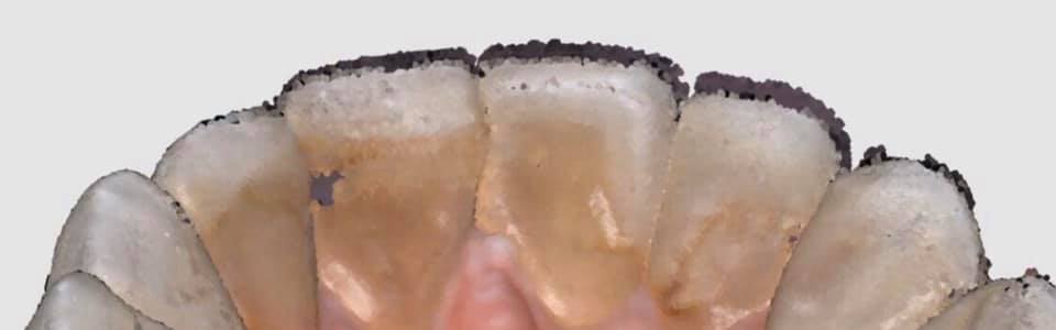
You can find margins outside the mouth! See the first video to appreciate the significance of this
You don’t have to deal with retraction or hemostatis at all
You don’t have to worry about sprue position. Many other systems force the placement of the sprue to a specific location often making the case more difficult to manage than necessary
you are not limited to just a few implant lines
you don’t have to worry about location of anti rotational notch
you can digitally alter the prep and get a virtual reduction coping in cad
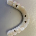
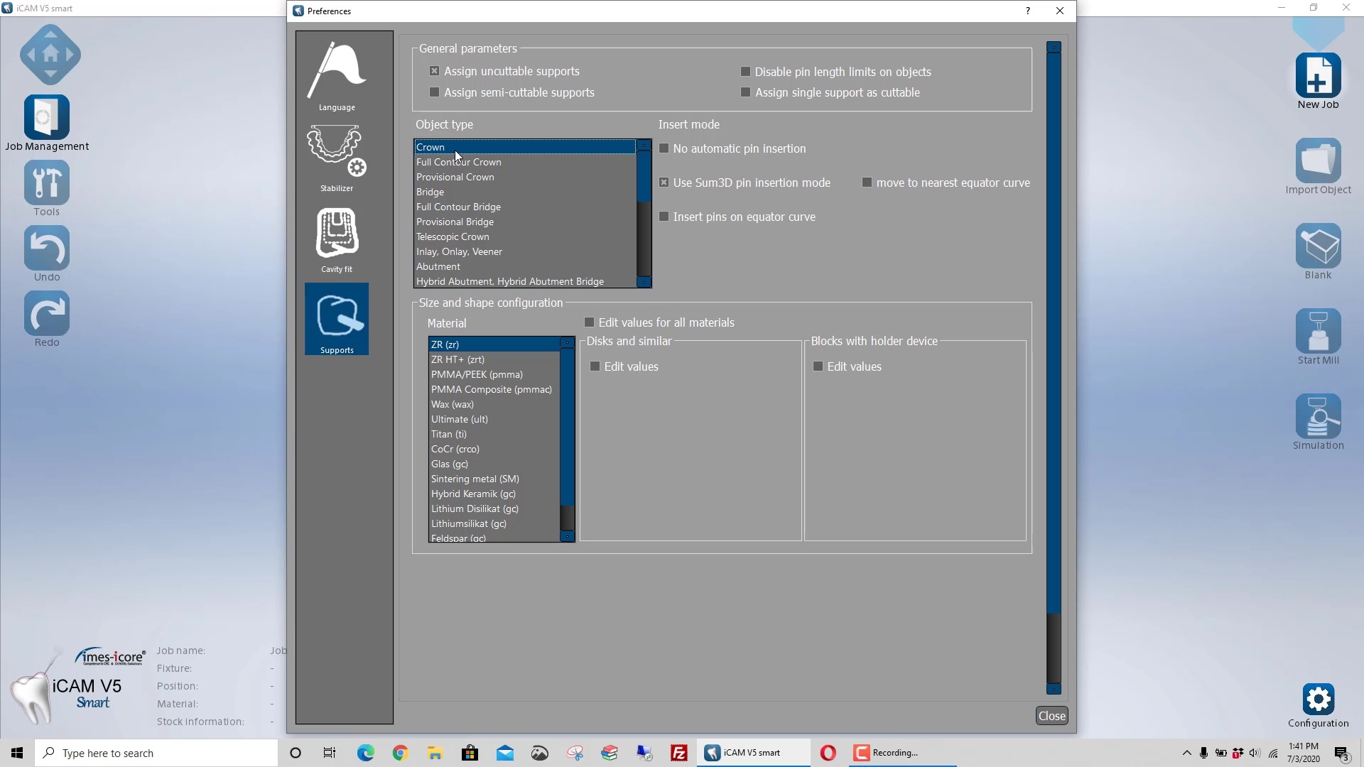
Use any restorative block you want. There is no need to order special blocks with pre-fabricated access channels and keep a large inventory of many colors. Your regular block inventory will suffice. Just make sure the top of the tibase is wider than the diameter of the drill used to mill out the intaglio. Also, the CAM and the milling machine determine the exact product and different settings maybe utilized to give you relief off the walls. Some will even remove the antirotational notch because the adaptation is so tight, the restoration will not rotate due to the tall walls of the tibase
You can check the fit outside the mouth on the same tibase or a one you keep chairside for every case to let you know that if you are not seating, it is clearly a contact or contour issue as opposed to an intaglio issue.
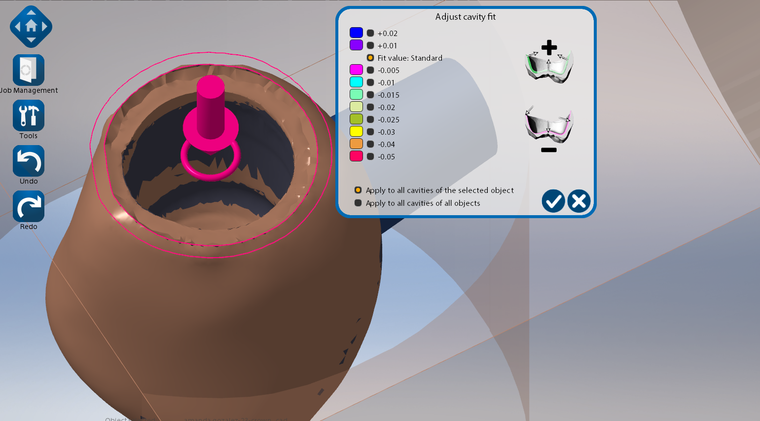
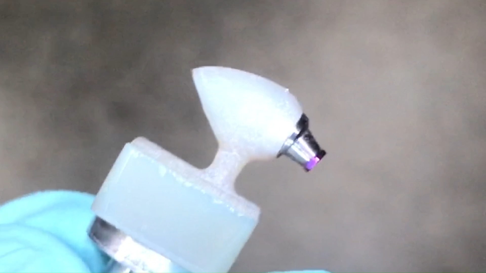
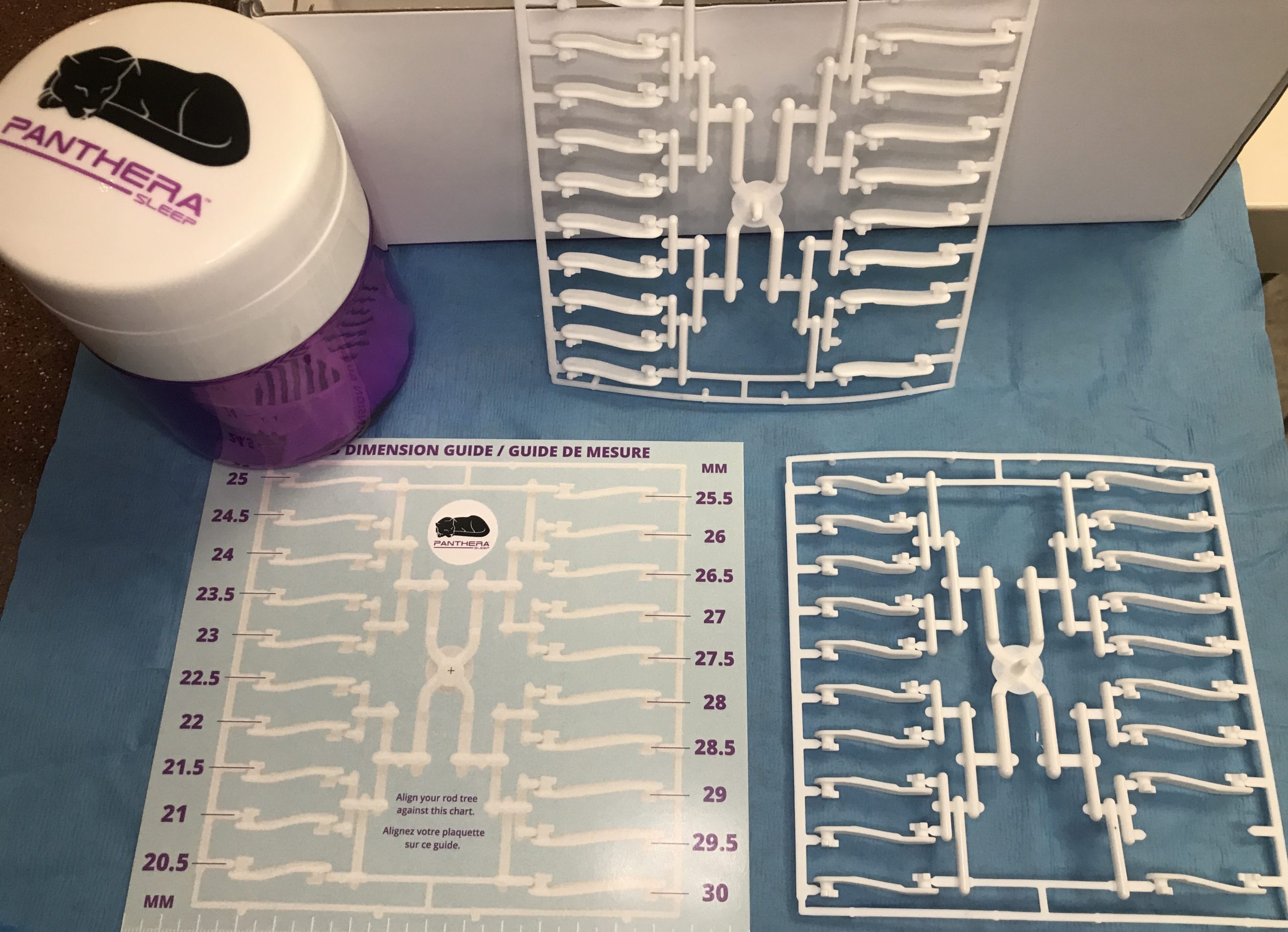
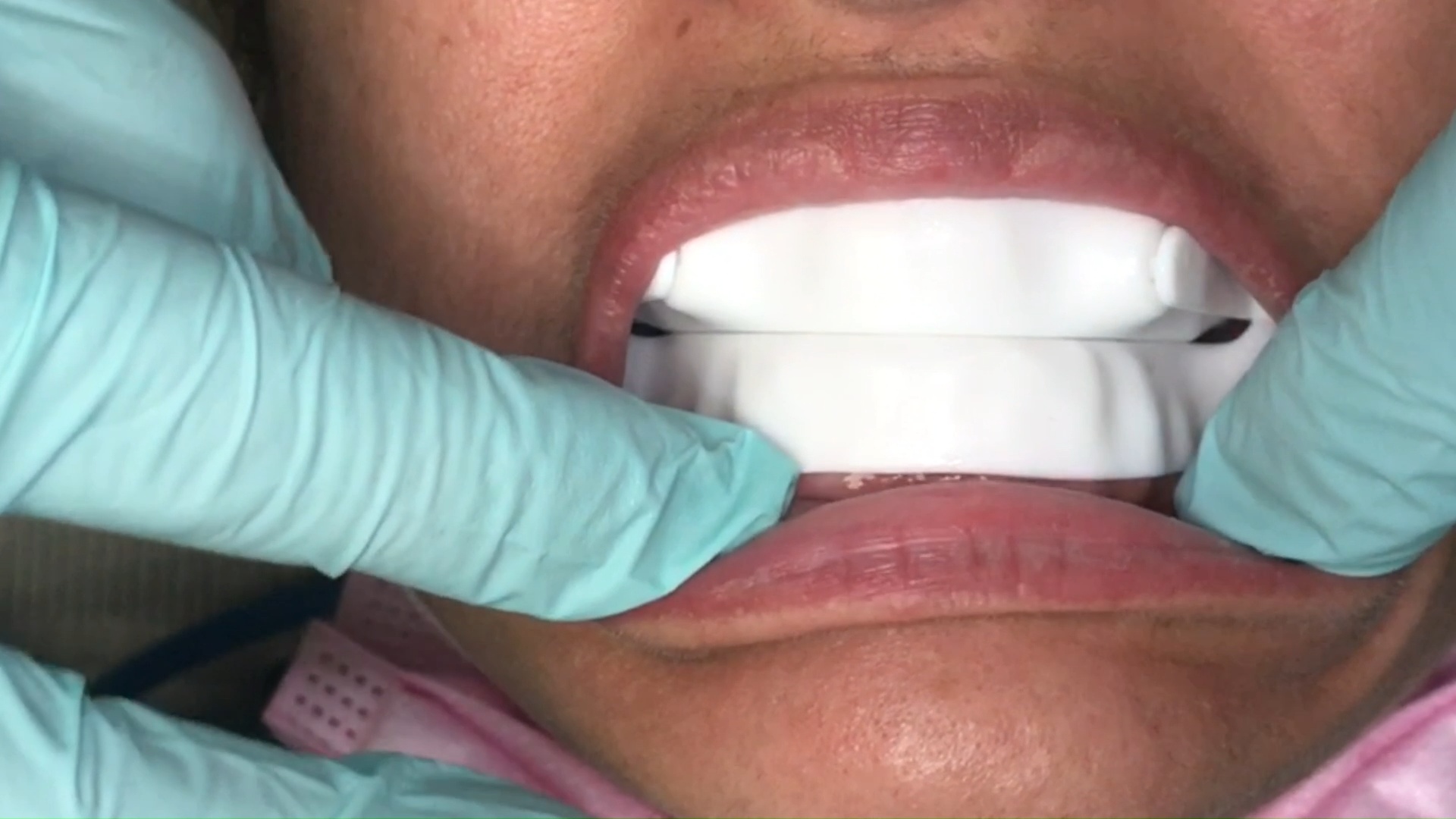
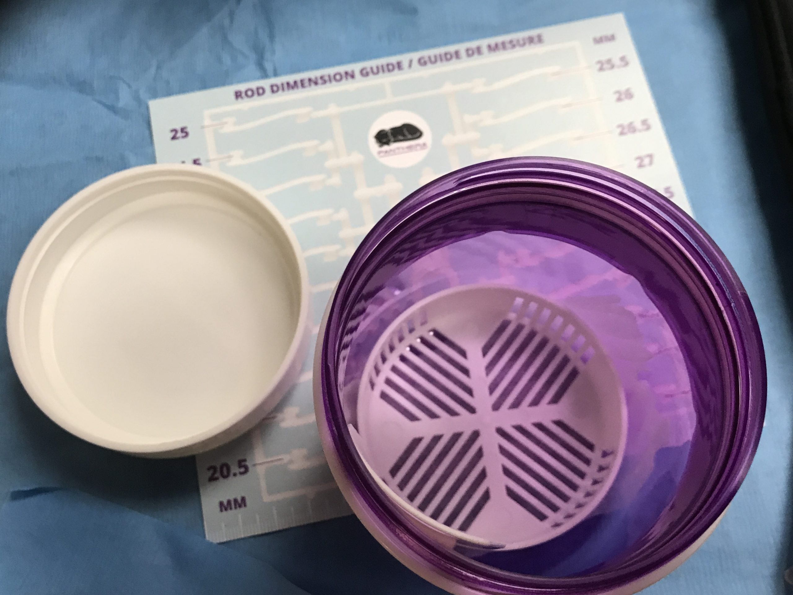
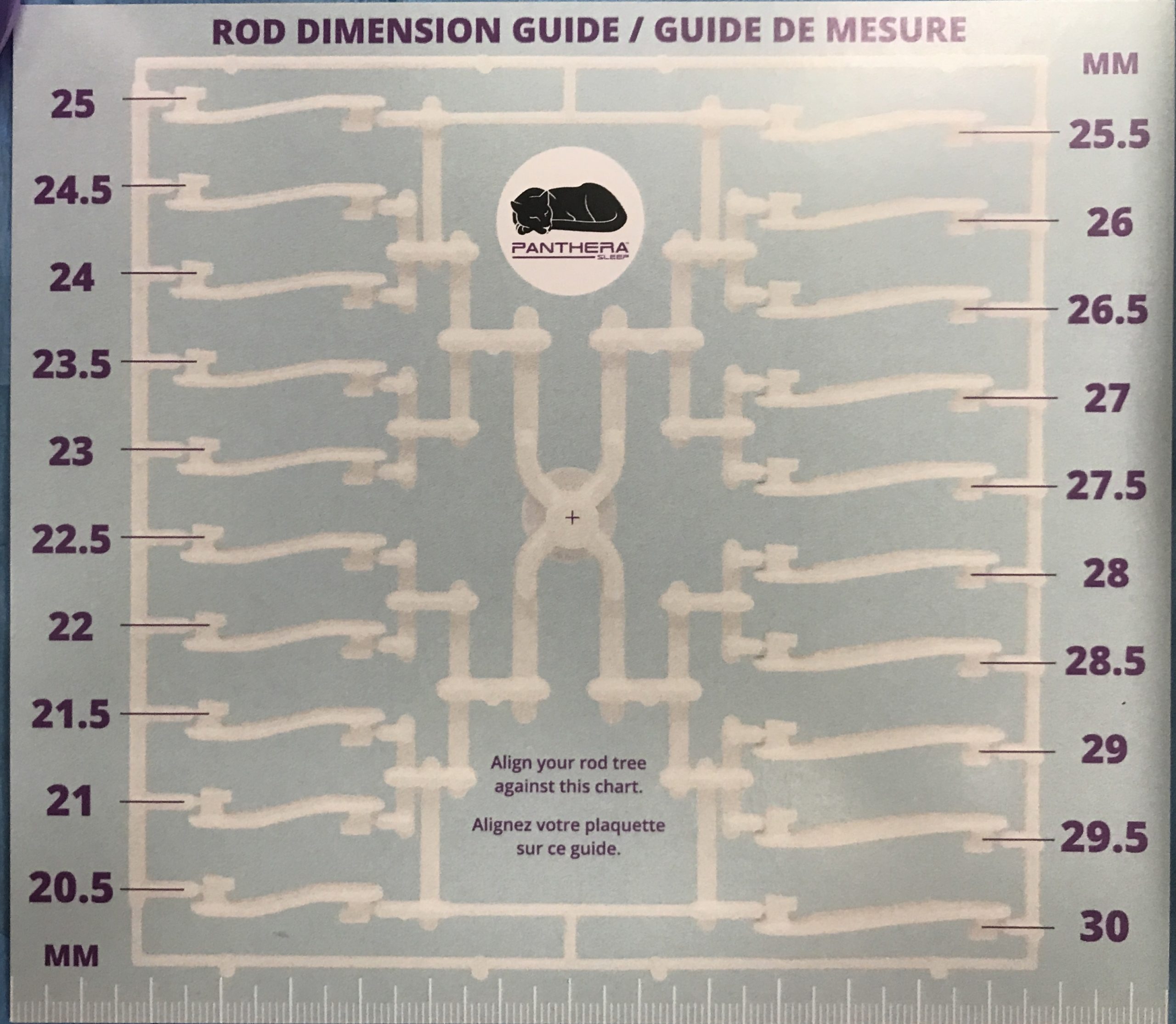
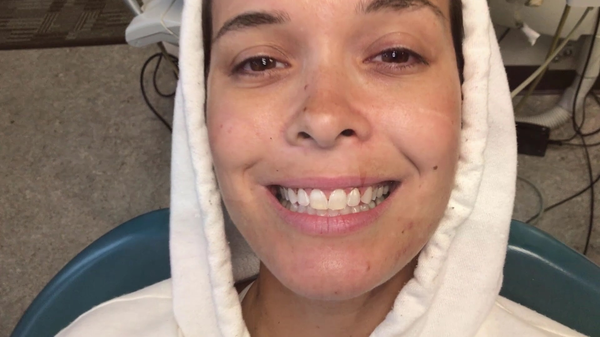
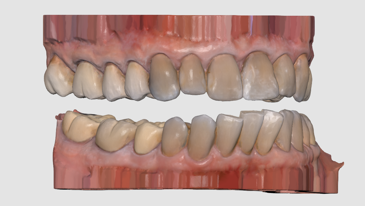
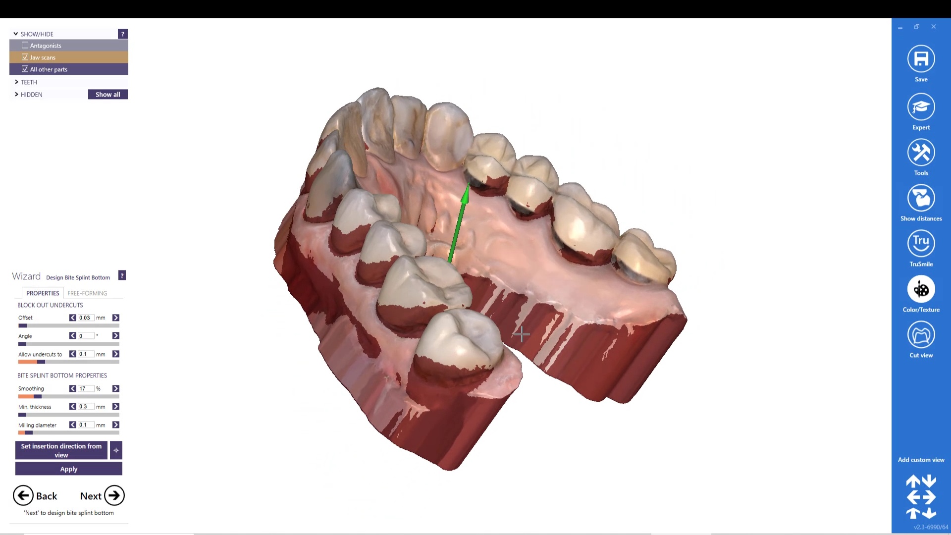
One of the greatest advantages of digital impressions and oral appliances is how there is very little post op adjustments to be made when you capture the vertical dimension correctly. Here, we deliver a Panthera OSA device with just an exam kit.
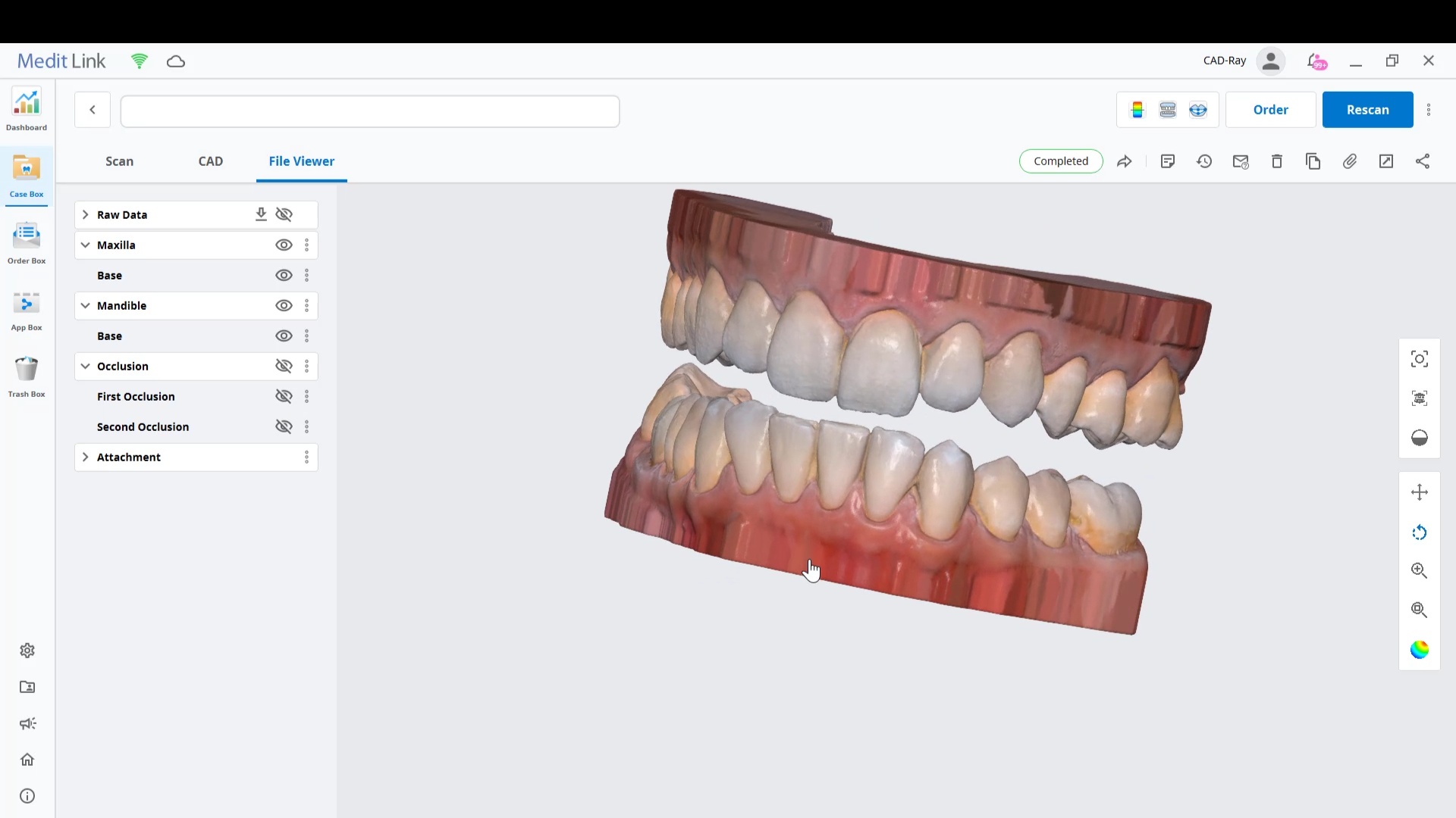
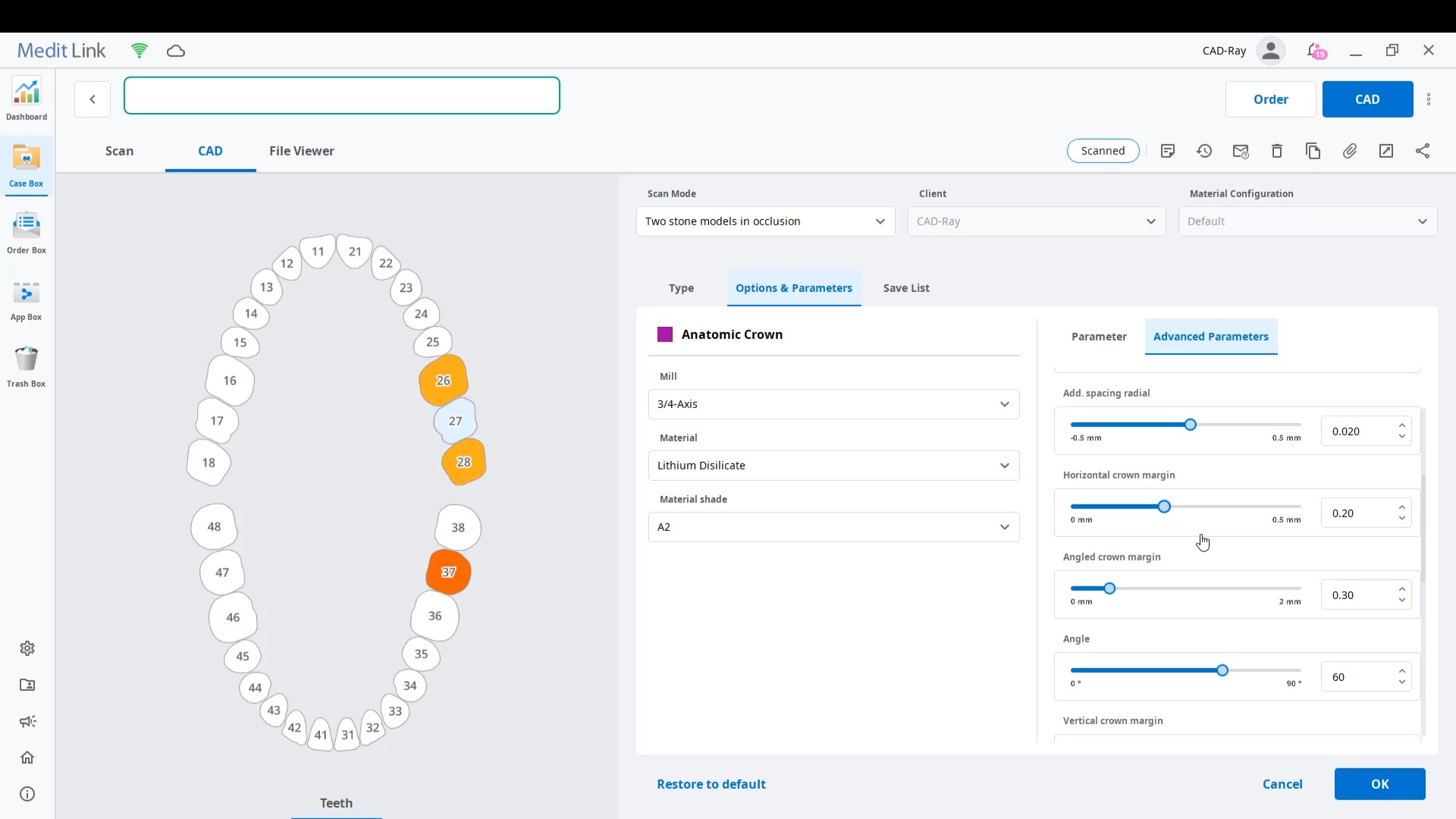
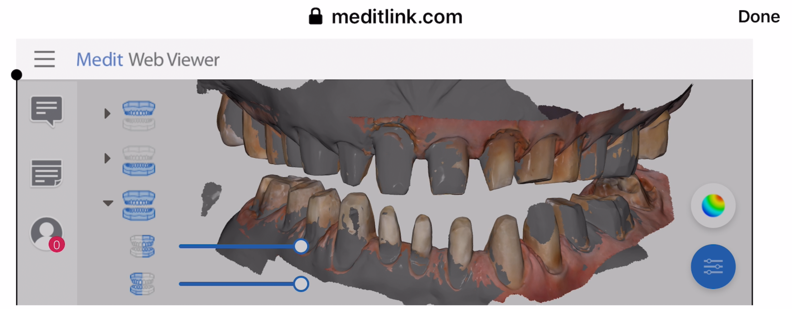
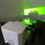
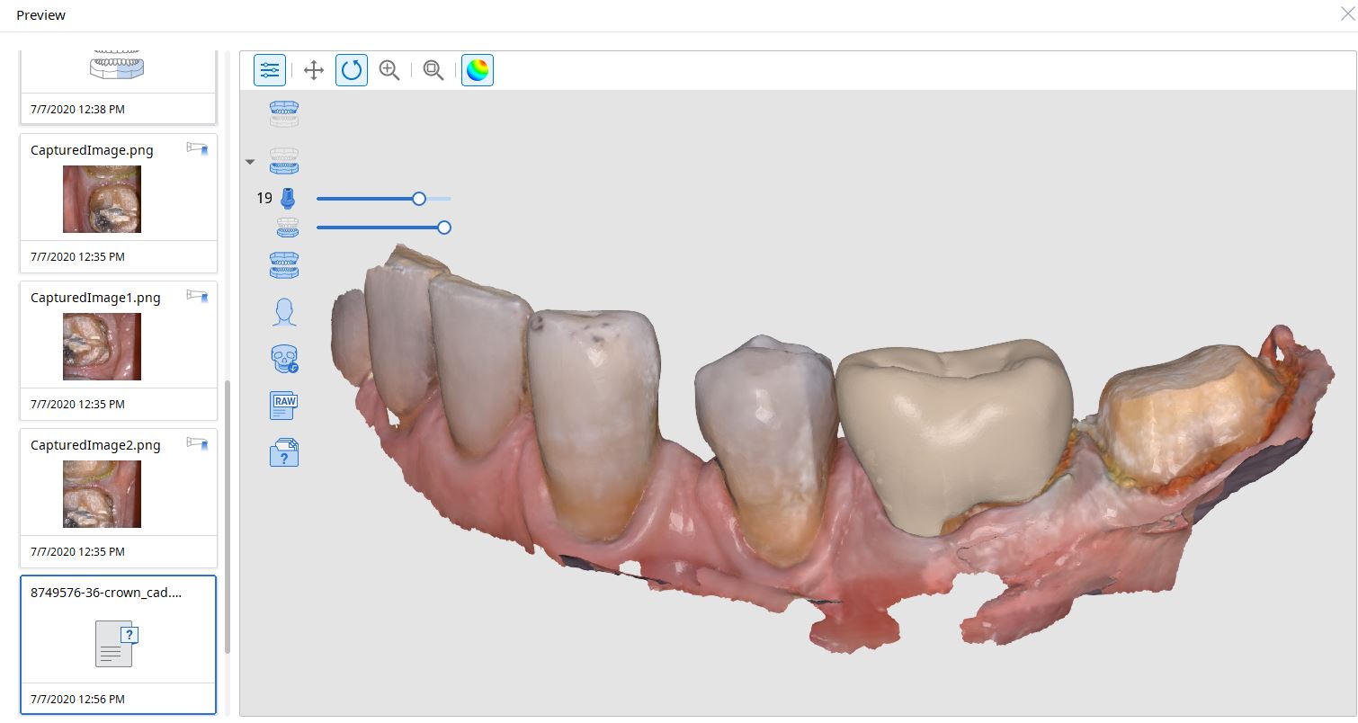
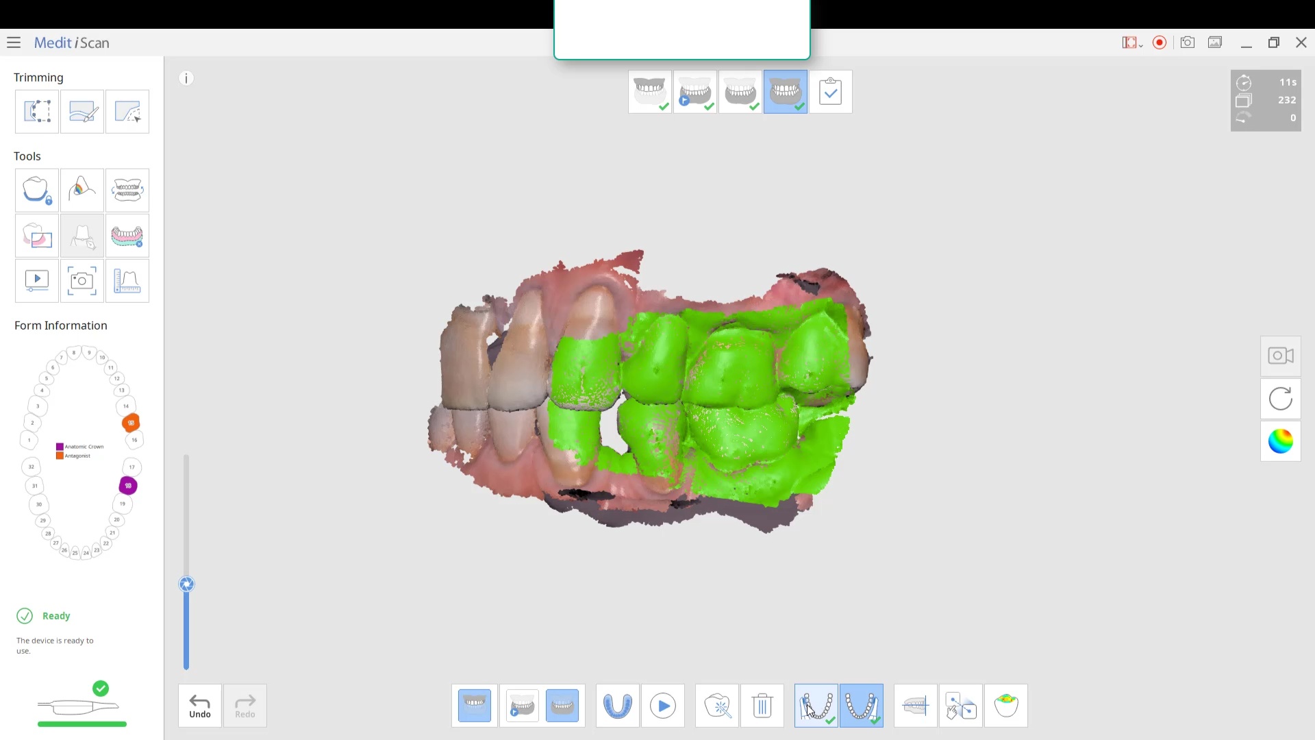
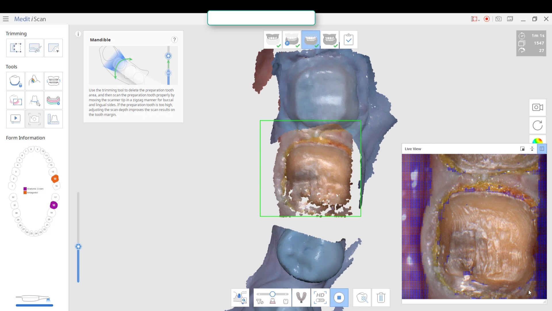
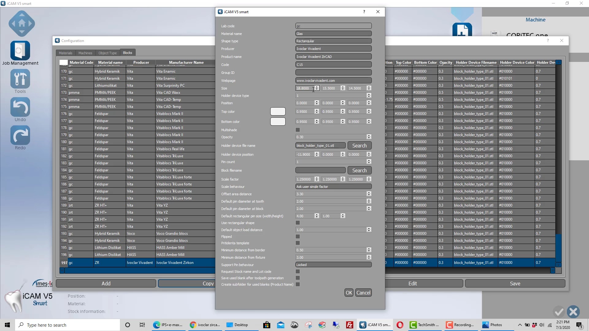
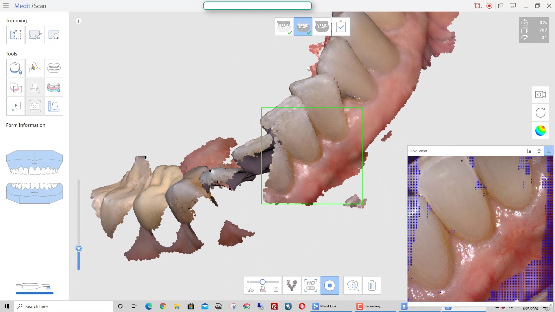
This article features the new Meditlink 2.3 software which has some advanced functionality. One of the greatest achievements is he ability to tell the scanner to avoid imaging certain colors like green and blue. This greatly facilitates the imaging of full arches as you can let your gloves / fingers guide the camera and displace all the soft tissue that impedes image capturing. We also feature how easy it is to launch CAD software to design the restoration and mill it out of lithium disilicate material
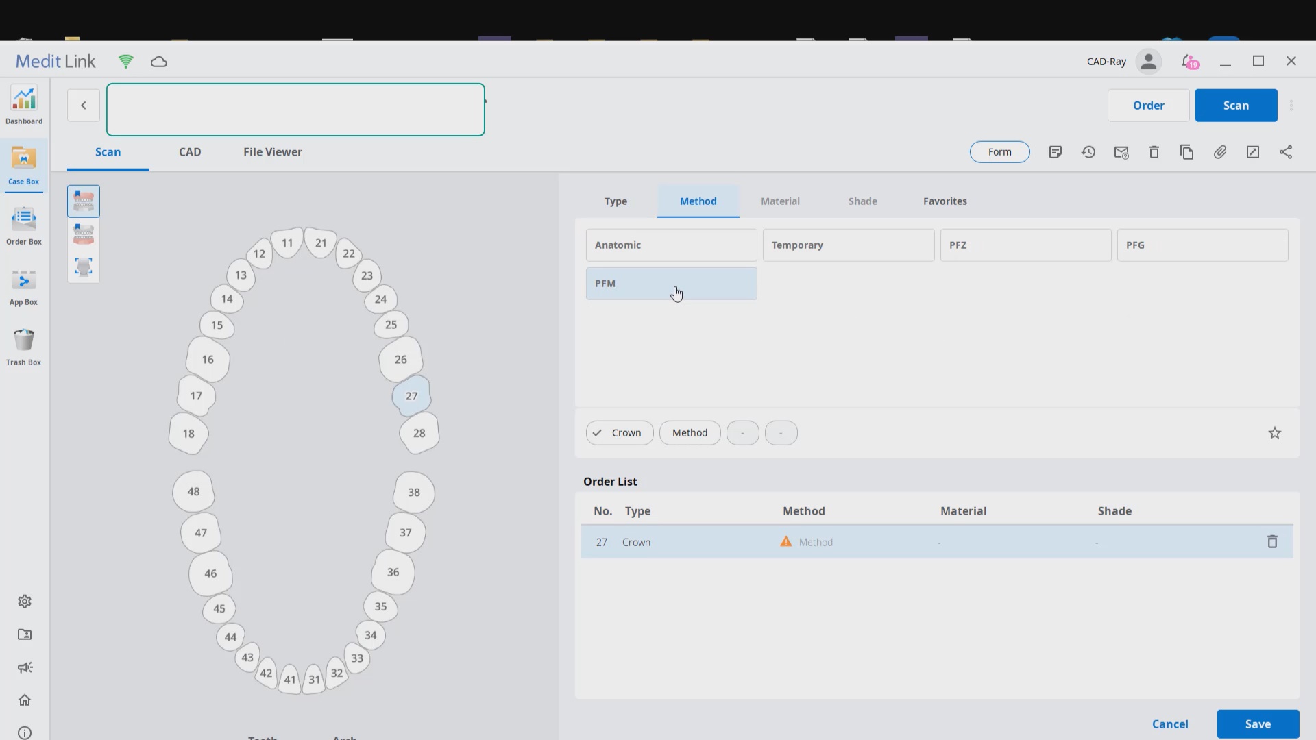
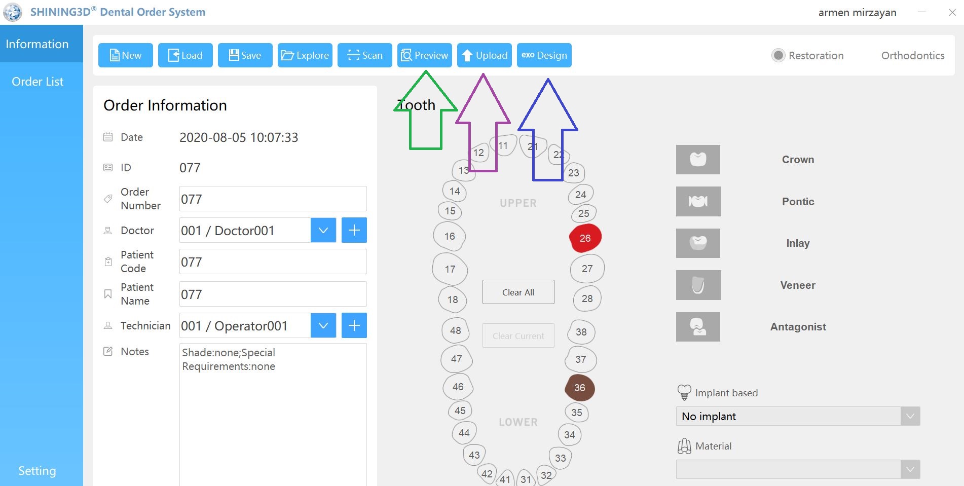
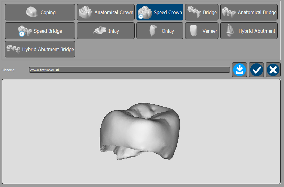
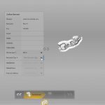
Case set up: here we enter the patients name and a simple tab appears where we chose the material and restoration tab. Once you image, you can place an order to the lab or you can advance to the CAD tab:
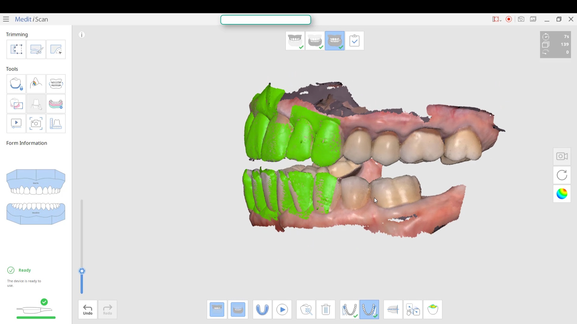
After the Rx has been filled out, you can launch the Medit Scan and image the upper and lower arches. Please note how we tell the camera to avoid the color blue and it ignores the clinicians fingers during imaging. The upper jaw and lower jaw were captured, then the bite registration even before the preparation was finished. This allows the verification of proper reduction and space for the ceramic material
Lower Arch Scan
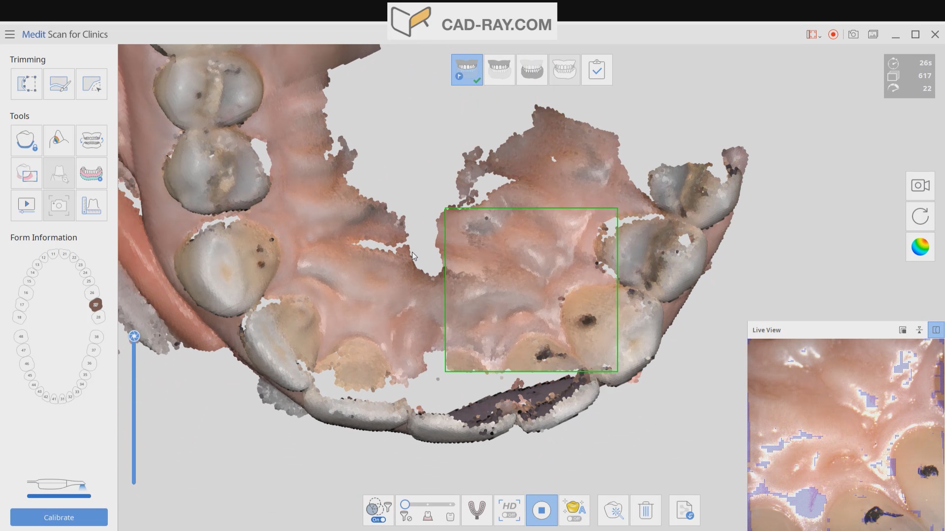
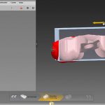
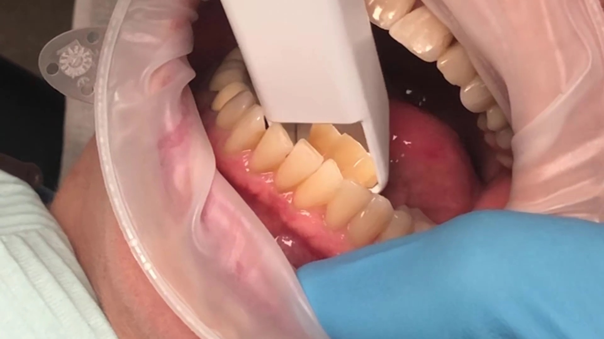
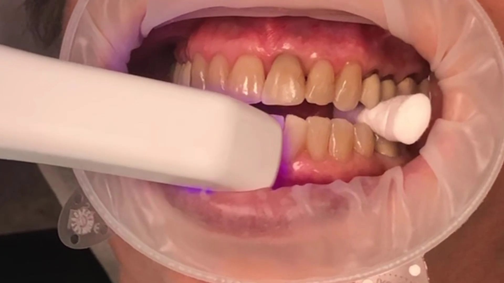
The lower arch is the most difficult area to scan as you frequently have to battle the tongue, saliva, and the lips. The optragate can be of great help but notice how we use the color filter to hide the blue gloves while we advance the camera. It is a great aid in facilitating the capture of the lower arch
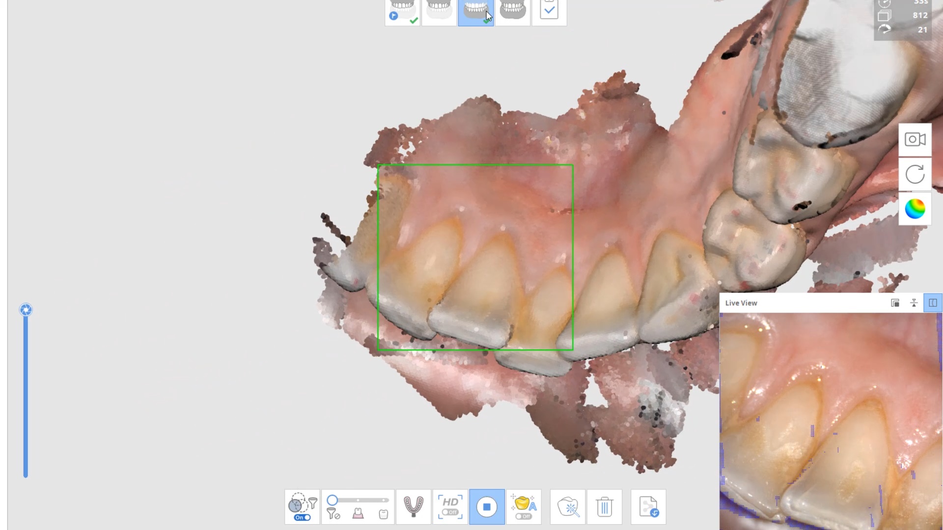
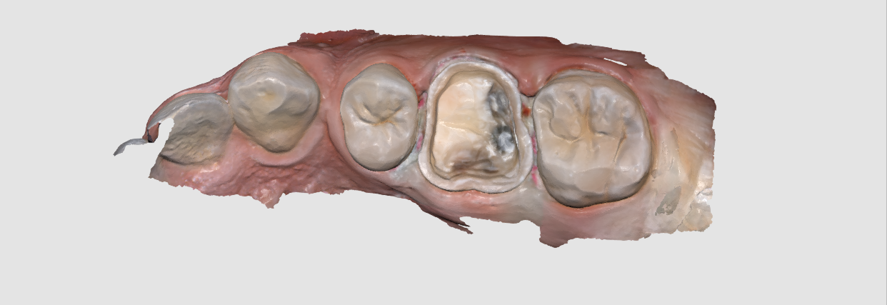
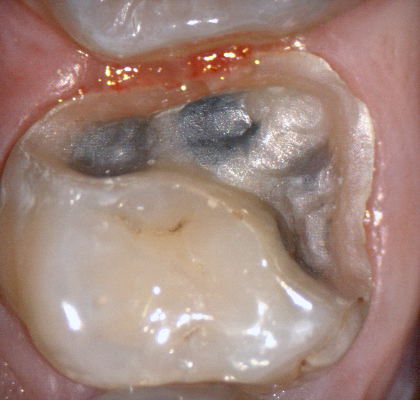
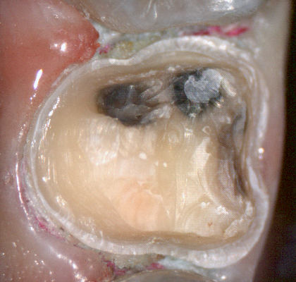
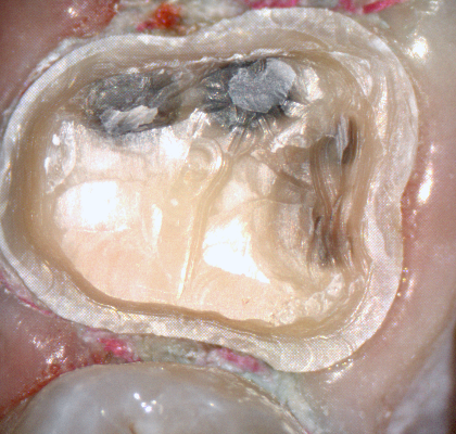
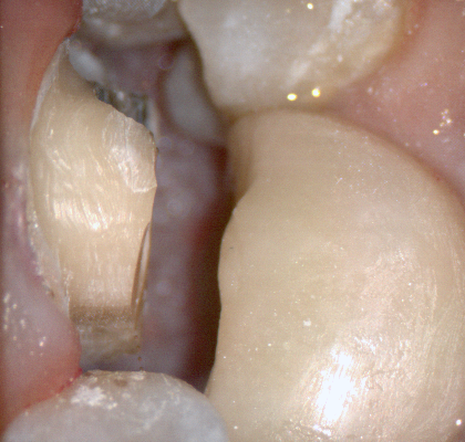
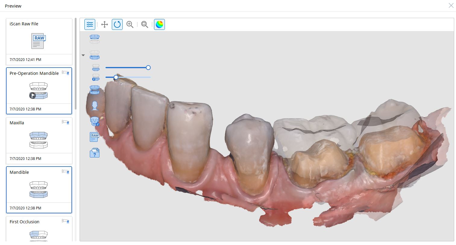
The same principle is applied to the upper arch. Notice that the software does not care if you start with the upper or lower arch. Here, you can visualize how the blue glove was used to displace the cheek and capture the pre-op condition of the upper second molar. The rest of the arch was easily imaged. It is not necessary to capture full arch impressions and this was done just for demonstration purposes. For a single unit case, generally imaging distal from the canine is adequate.
Checkingthe reduction and aquiiring the bite registration
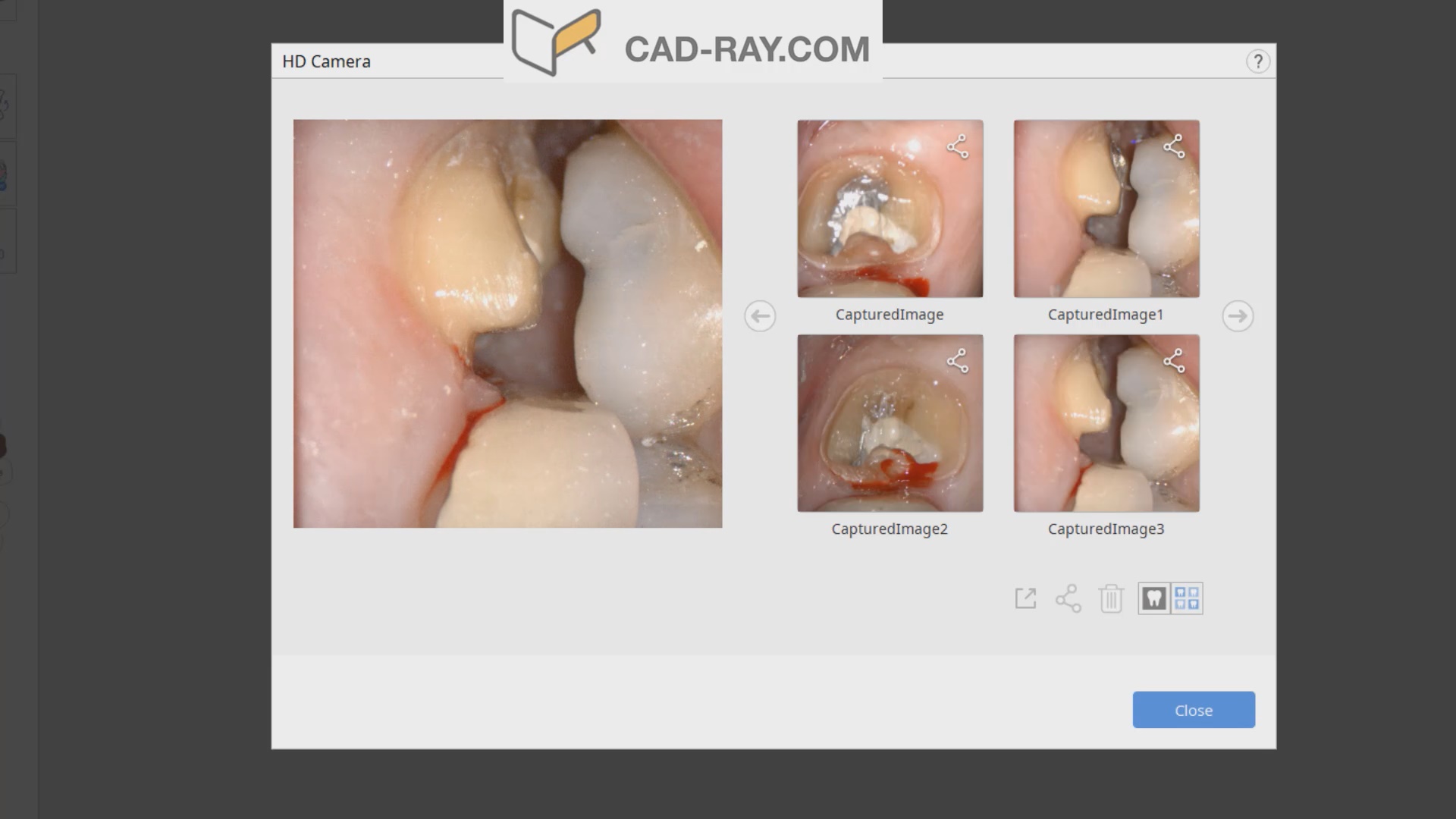
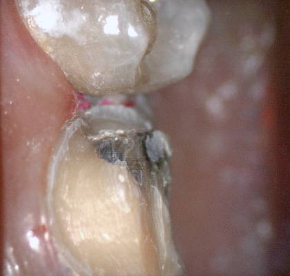
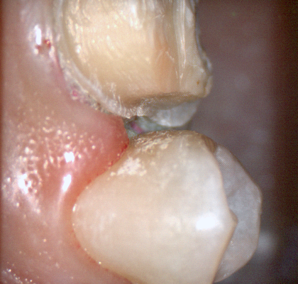
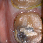
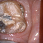
We recommend that you capture the bite before you finish imaging the preparation. This gives you one last chance to verify that you have reduced enough to accommodate material thickness. You can see how we just take regular photos to document the lack of clearance and we continue to adjust the height of the preparation until we achieve the required space. We then activate the imaging process and capture the occlusal relationship between the upper jaw and the lower jaw
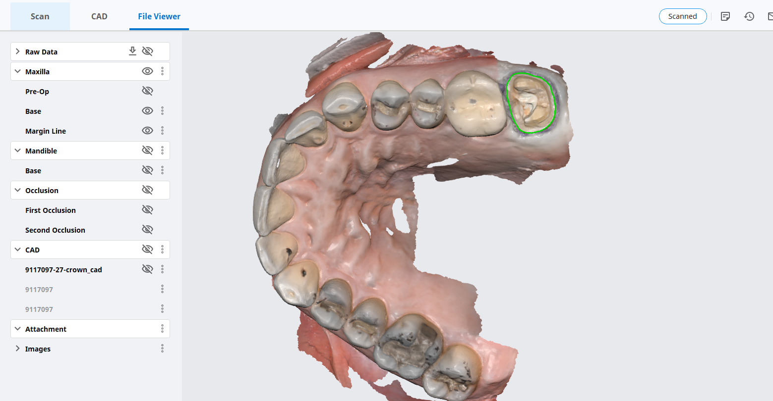
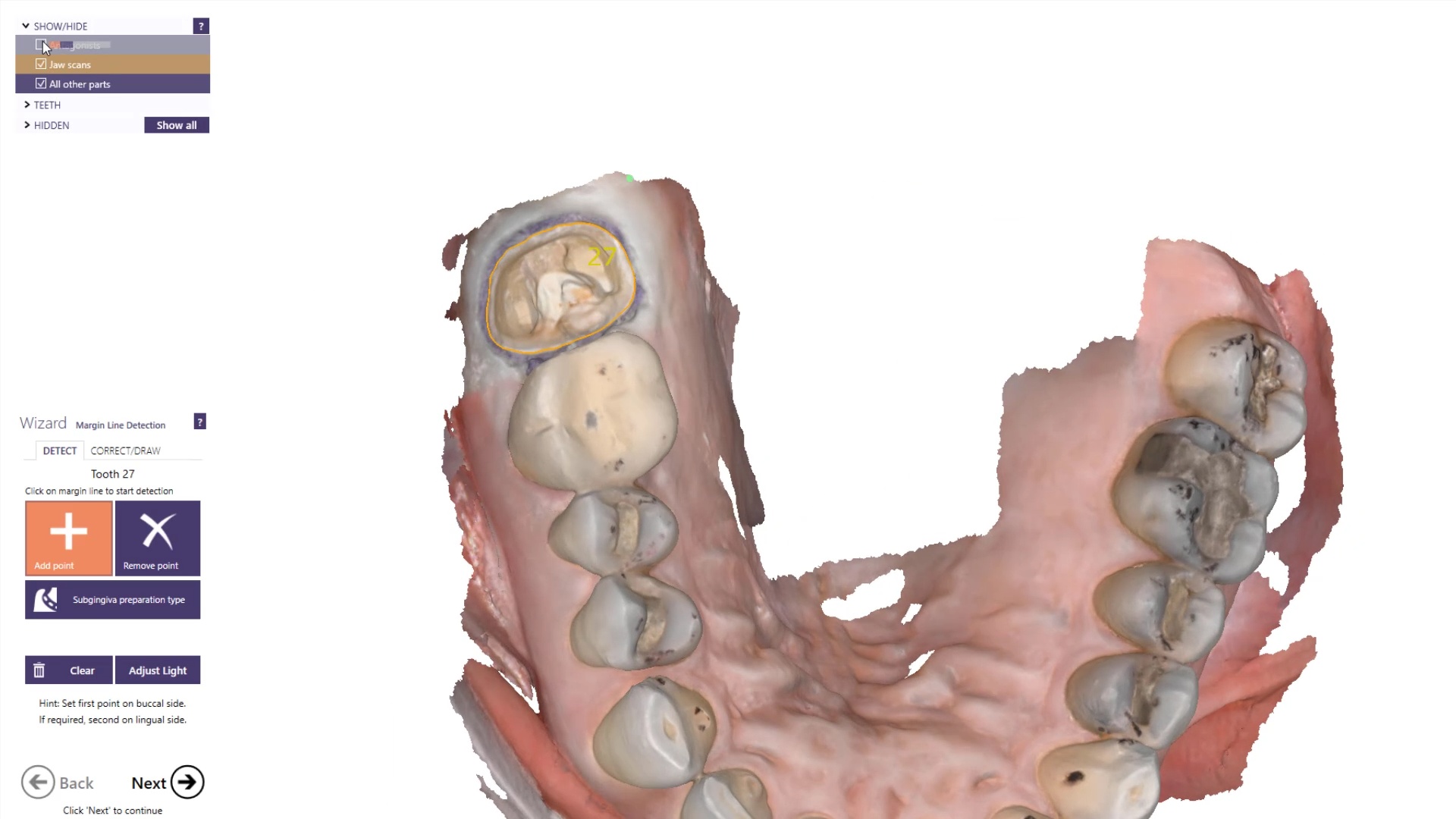
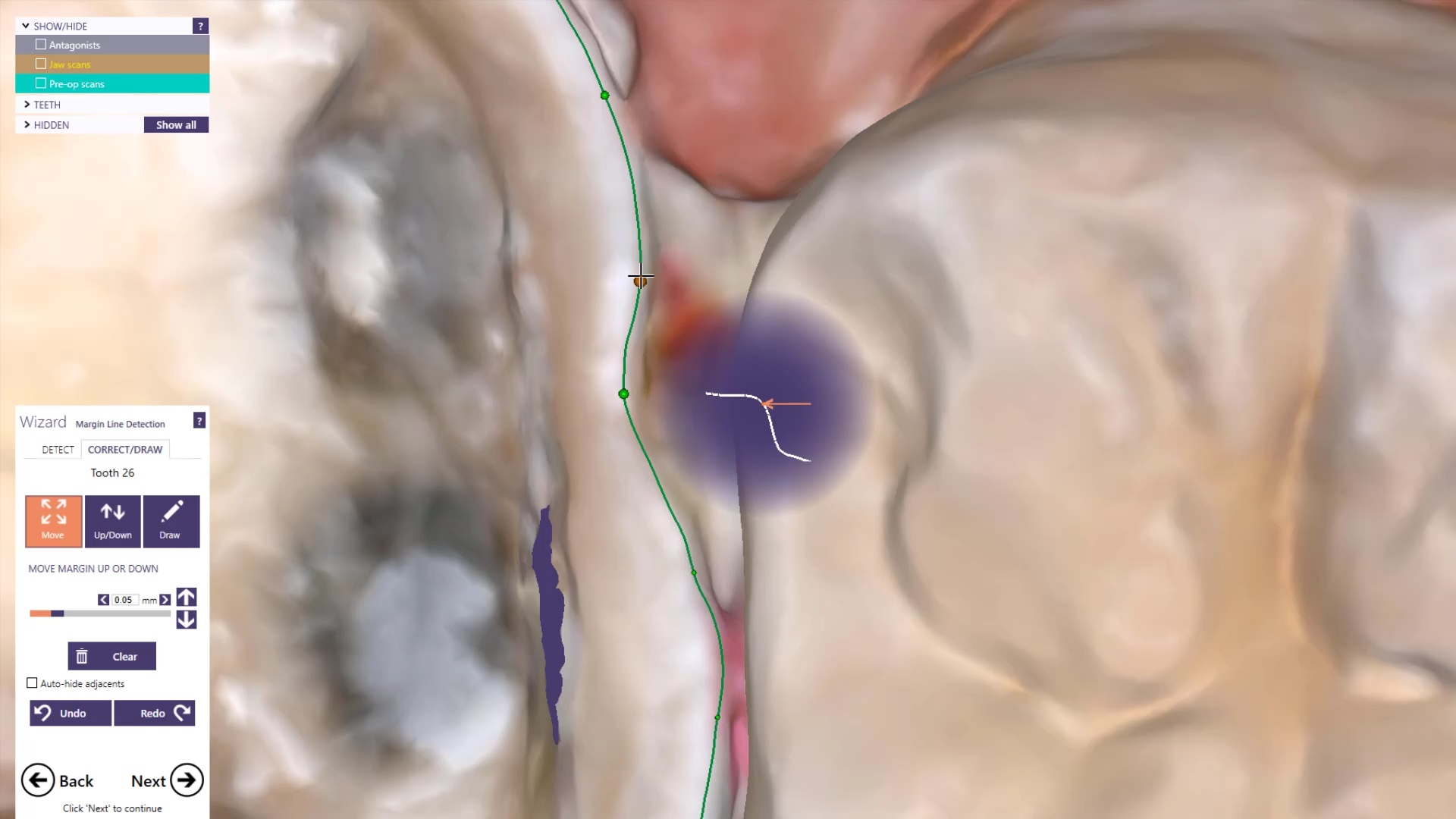
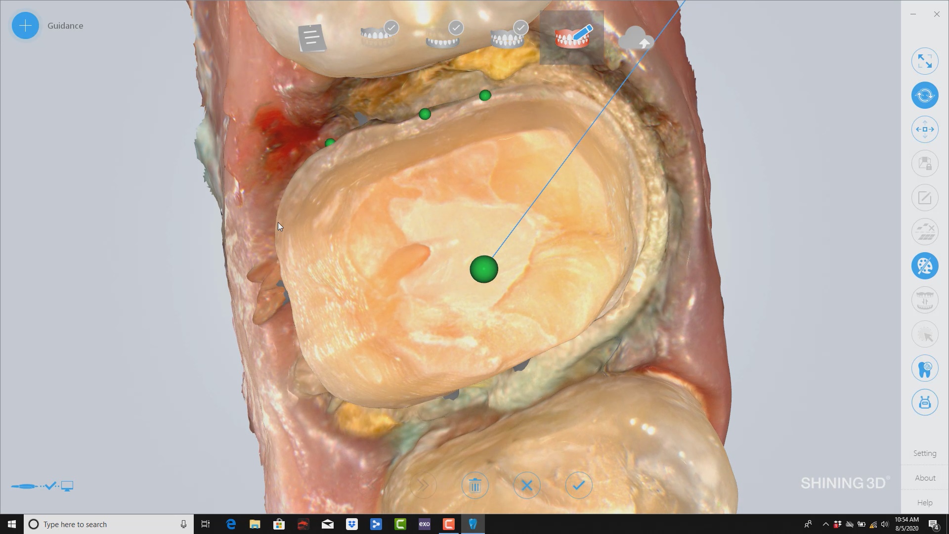
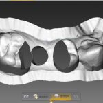
Image the preparation and place margin in native MeditScan Software that transfers to CAD Software
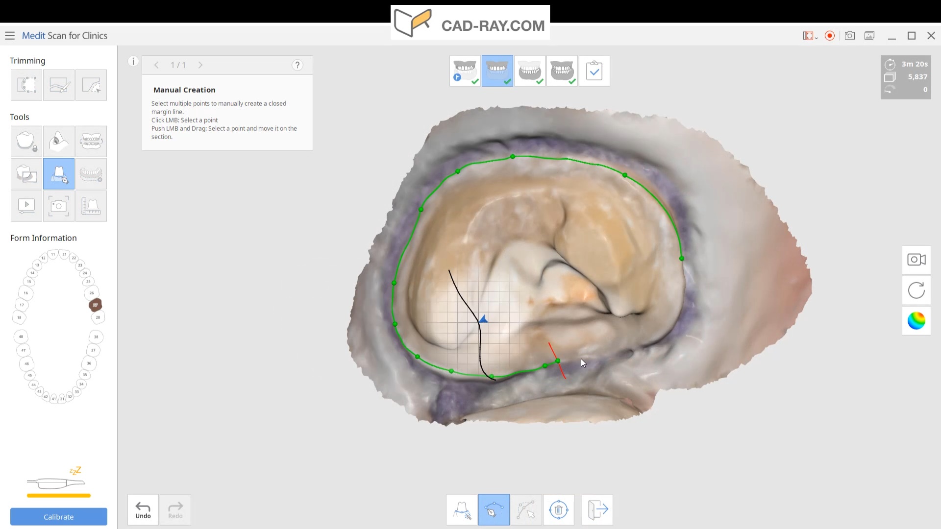
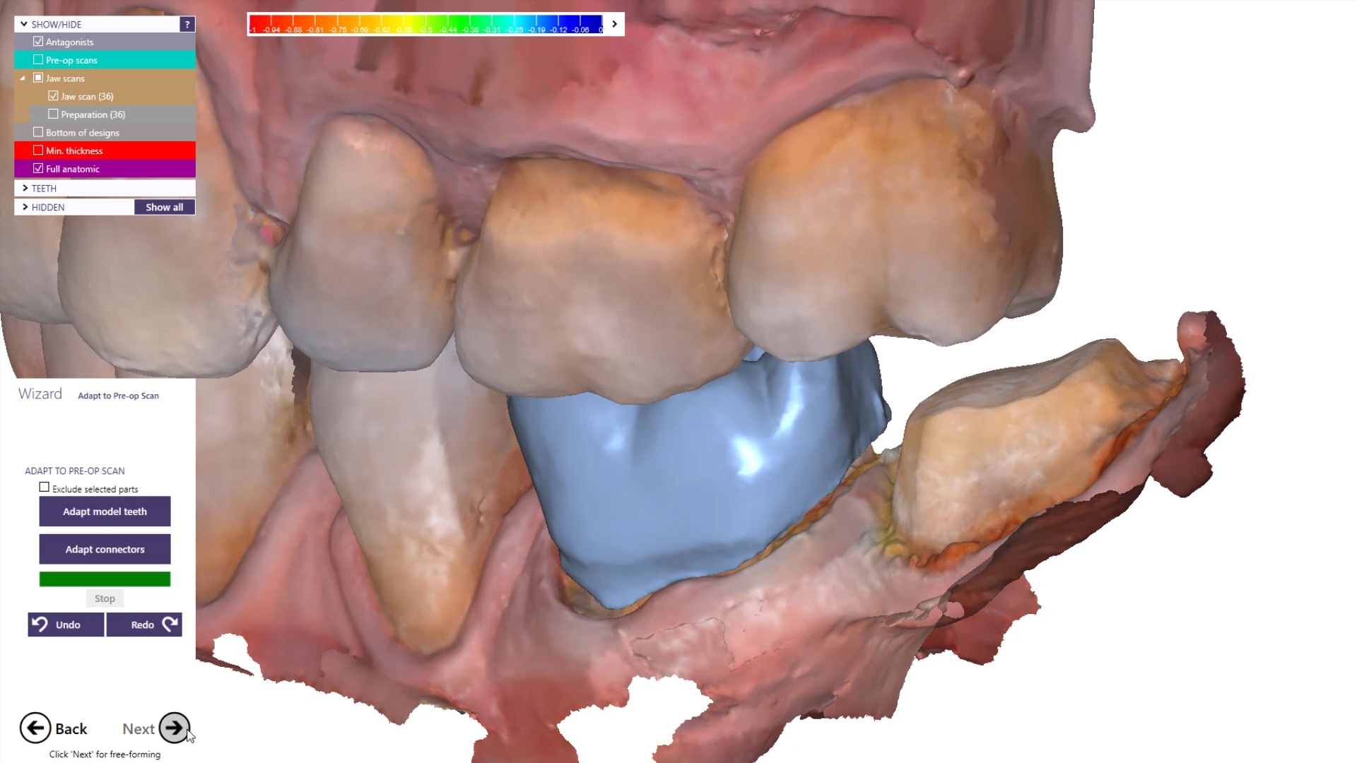
The preop condition is then transferred to the arch model and the tooth in question is cropped out. The rest of the arch is protected so no extra data is added unnecessarily to the equation. This protect feature is used for demonstration purposes and is subsequently removed. The prep in question is then highlighted and the local area is processed and the margins are placed. This margin line can be sent to the lab or it can be automatically carried to the design software
The Meditlink software allow you to launch a variety of CAD programs that include 3shape, exocad, cerec, etc… Here we launch exocad which automatically imports and aligns the models and marks the margins. The restoration is then designed to completion.
The CAD software allows you or the lab to alter the marked margins if necessary. The restoration is aligned in the arch for and the contacts are adapted to the adjacents and the oppising
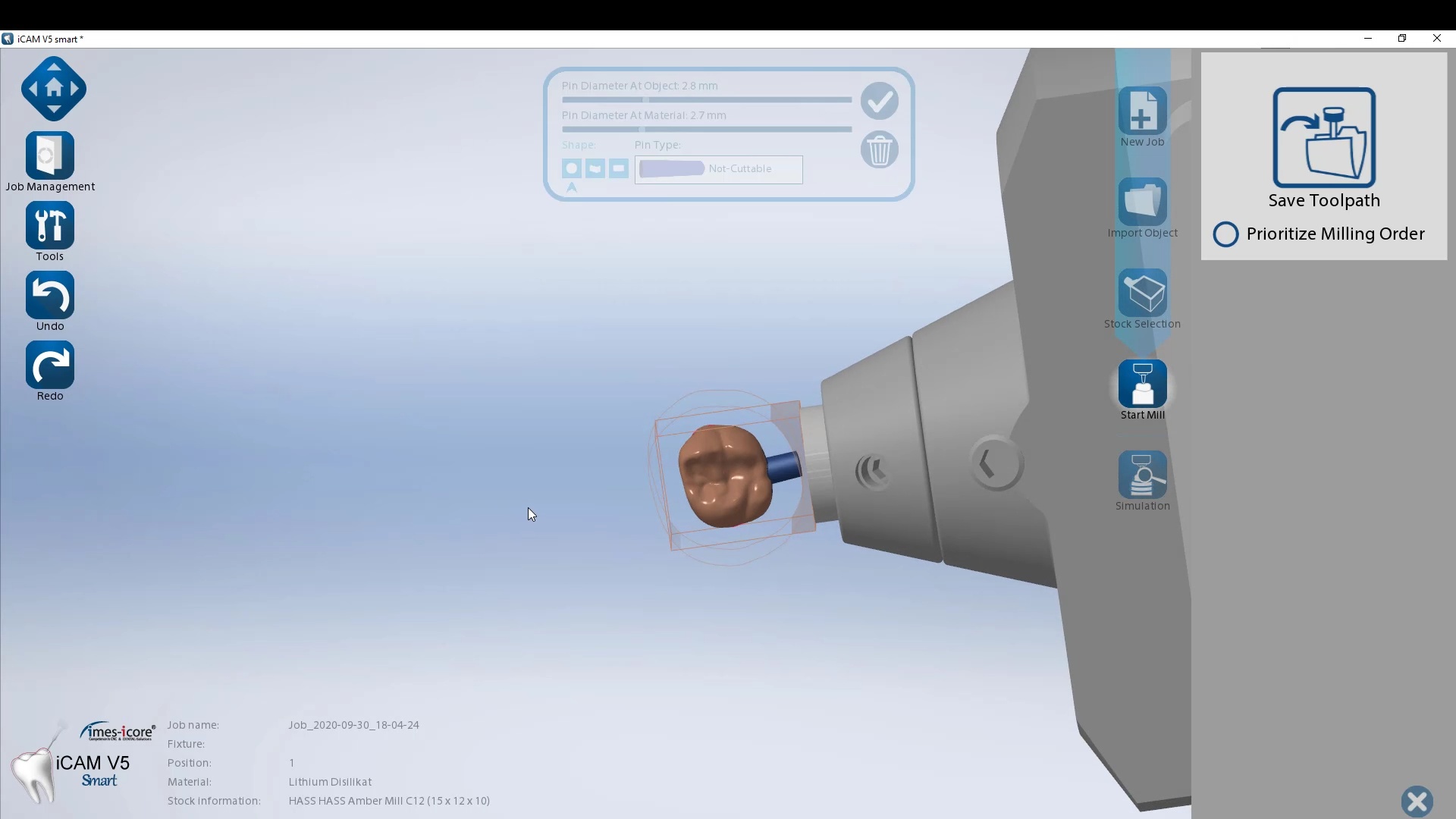
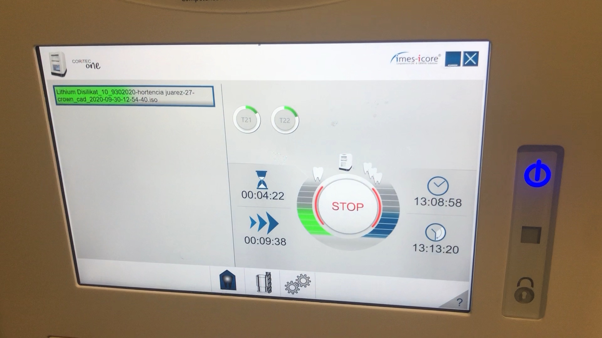
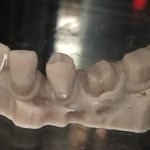
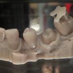
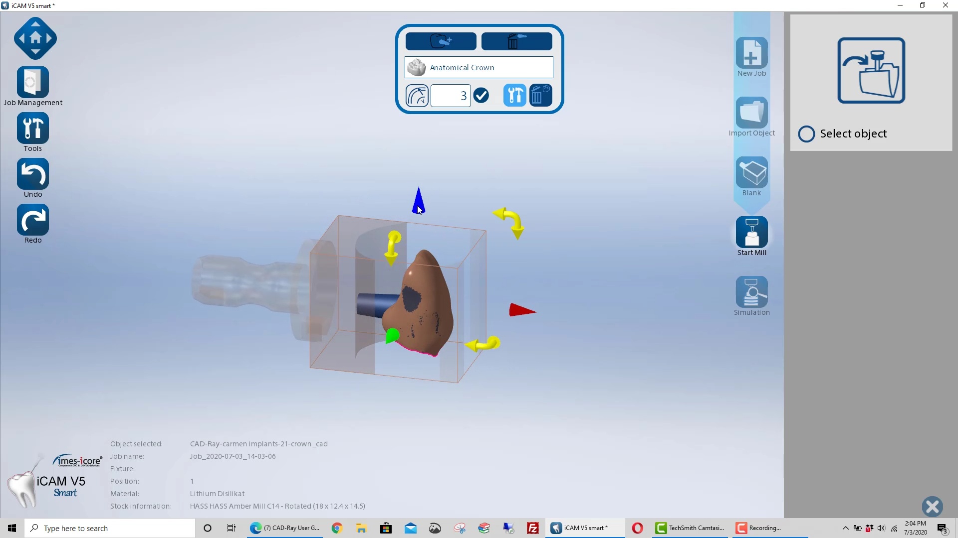
Milling of Lithium Disilicate with Imes Icore Coritec One
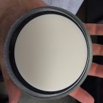
The final restoration design can be exported as an stl and taken to a variety of mills or printers. Here we designed it millbox and milled with the coritec One. The material used was Amber Mill and it was crystalized and seated
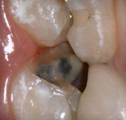
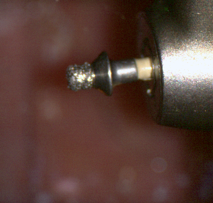
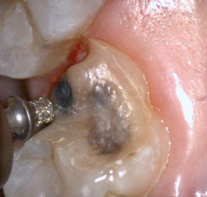
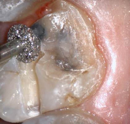
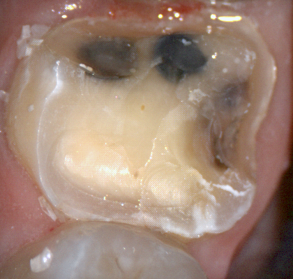
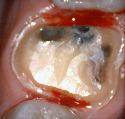
The following pictures depict the sequence of burs we recommend that you use to finish a preparation quickly. While patient is getting numb, take a quick look at the clearance you will need to reach proper material thickness. Once the quadrant is isolated with isolite and optragate, take an occlusal router bur and create a trough to gain the proper depth. Follow that with a flat disk, and you can quickly reduce the occlusal height.
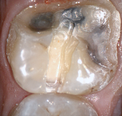
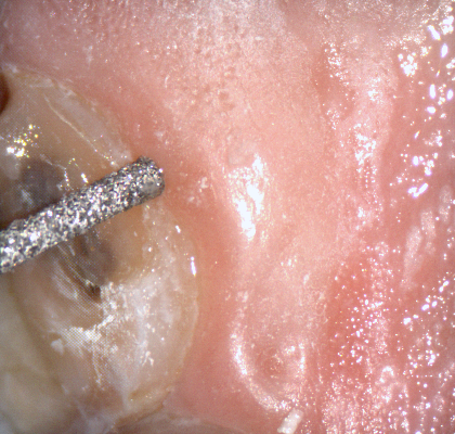
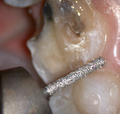
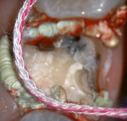
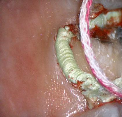
A shoulder bur of .8 mm thickness can help you reduce the interproximal areas as well as the buccal and lingual margin lines. Before finishing the prep, place hemostatic agent like expasyl in the sulcus and place retraction cord. while it is setting, check your reduction. If you need more space, now is the time to reduce some more.
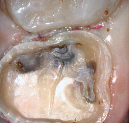
Once you have adequate clearance, retraction, and hemostatis, you can readily image and find your margins in the CAD software
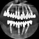
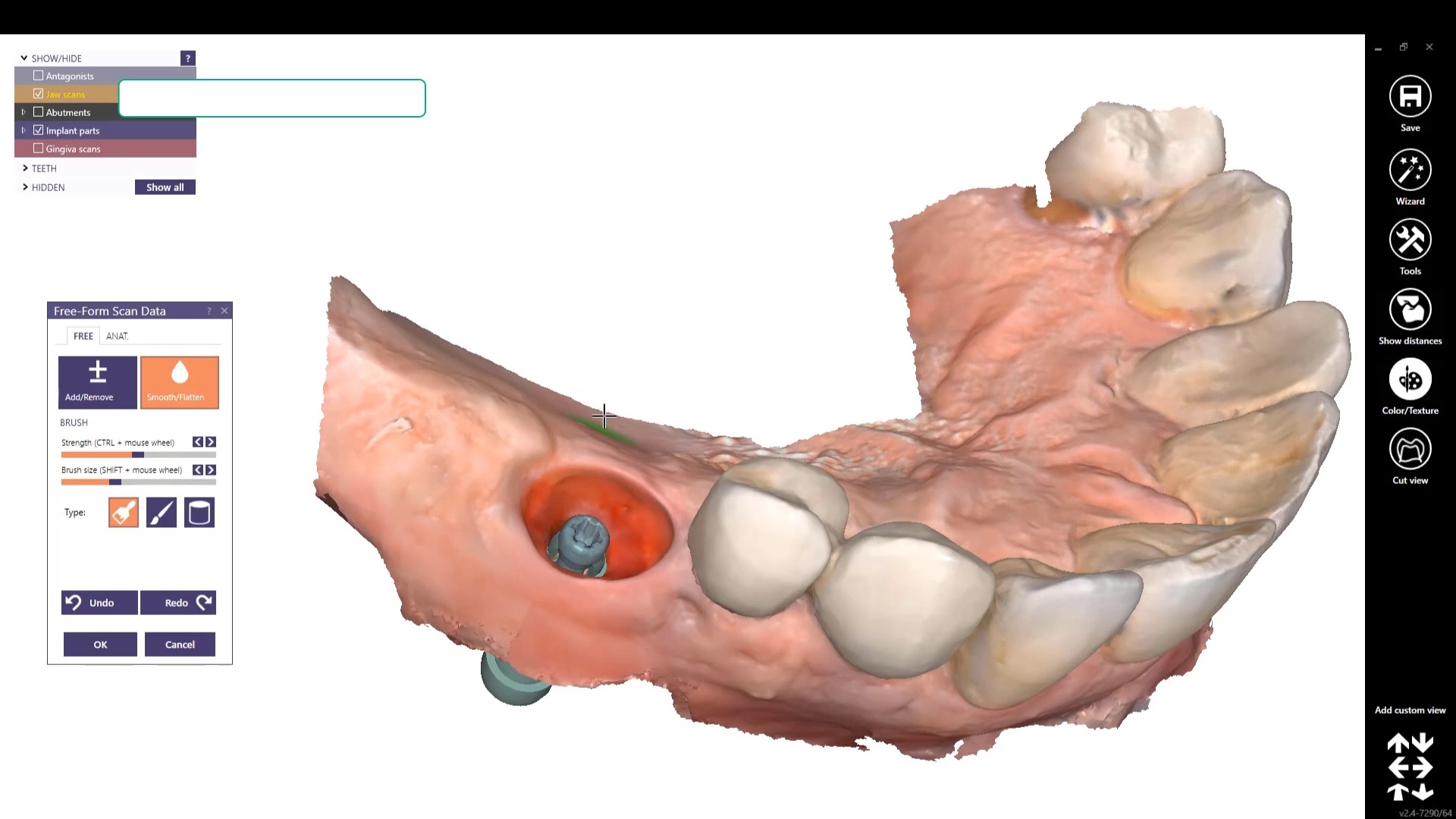
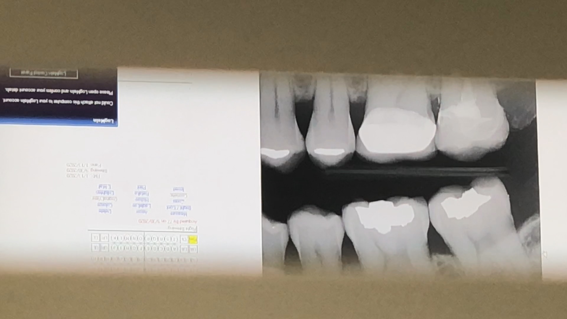
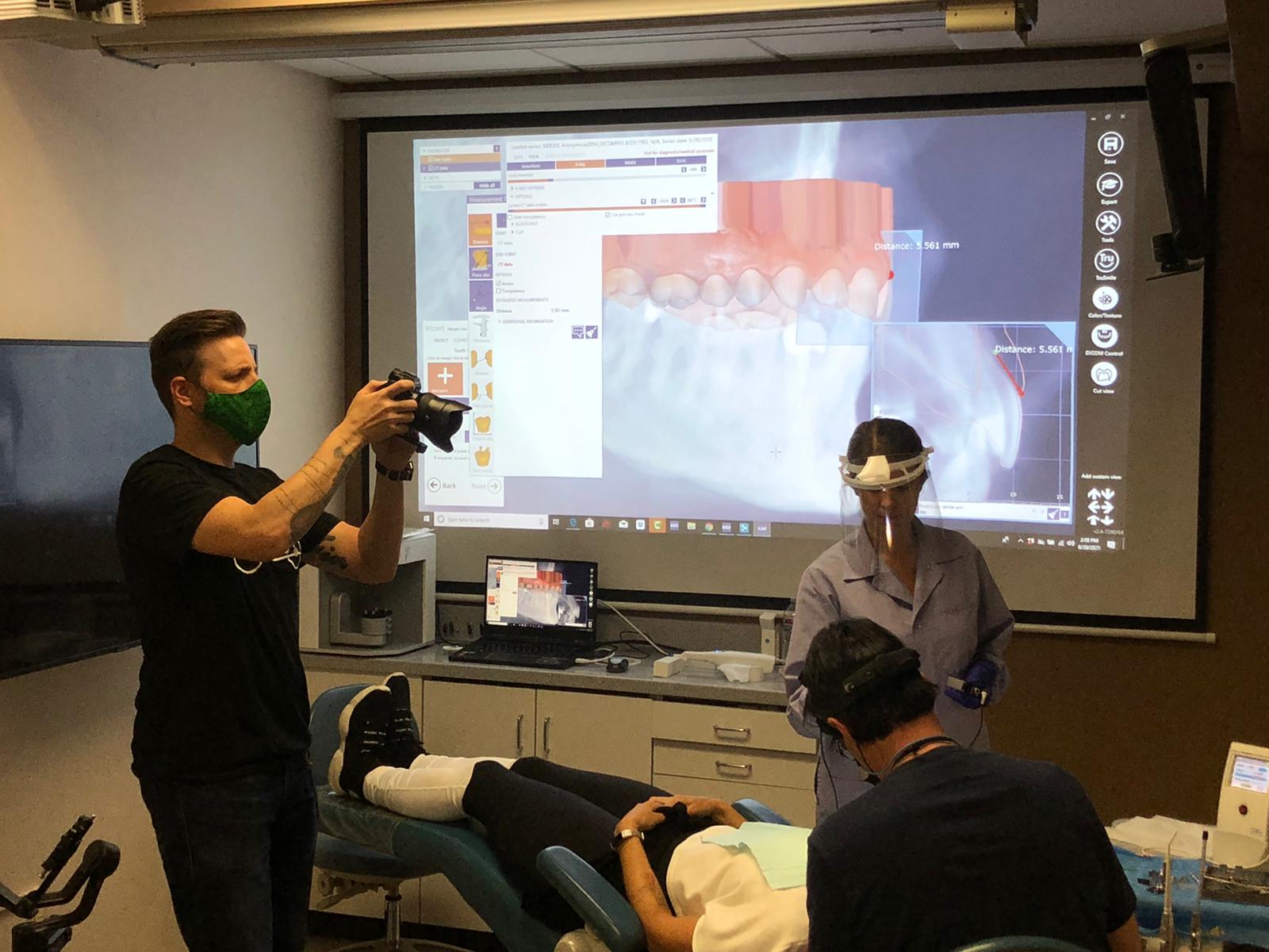
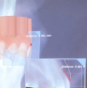
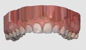
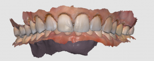
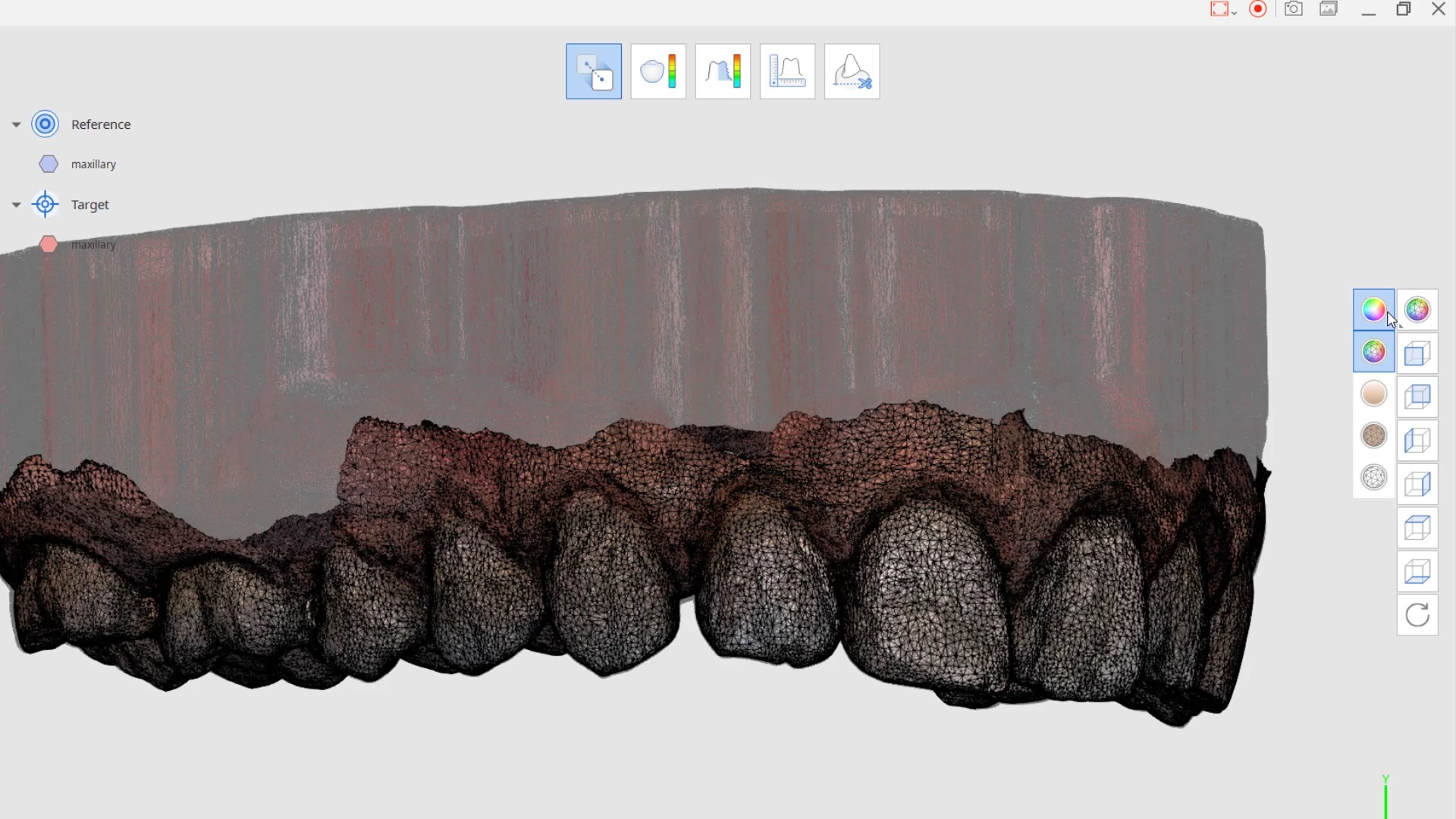
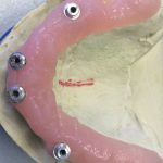
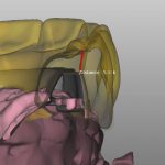
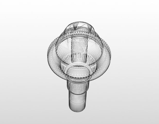
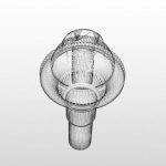
A Medit i500 scan was taken and merged with a CT scan and the distance to bone was measured (5.5 mm’s) giving enough space for soft tissue contouring with a diode laser. The 3D X-ray must be captured with cotton rolls placed in the vestibule so that you can differentiate between the gingiva and the lip. Ideally you should not close the base of the digital model by the intra-oral scanner as it can make the merge of the data sets more difficult than it needs to be.
I am not one to place much faith in published articles from academicians. I usually draw my information from trusted colleagues and also a very reliable source, Mr. Andrew Sedler, from Advanced Technology Centers in Burbank California. He is in charge of manufacturing thousands of full arch restorations for clinicians and many other labs that outsource their manufacturing.
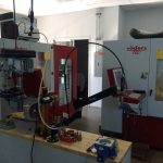
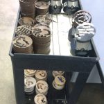
One of the things I always get a kick out of is whenever they do purchase technology or implement a process, they always have to do it with redundancy. What that means is that their machines can never go down for whatever reason, so they always purchase printers and mills by multiple sets. Interestingly, I was witness to them incorporating printers into the lab about 6-7 years ago and now they have a large wing dedicated to printing with over 20 machines for many different purposes.
I trust his judgement and always follow his recommendation and tested methods. When he says “do not bypass verification jigs, no matter what scanner was used”, I don’t even question it. He sees all the cases many entities can’t manage and he can manufacture any screw, prosthetic, abutment, etc… with their high end milling machines. In fact, it was on his word alone we decided to distribute the ICam4d by imetric.
I thought it would be a good idea to revisit full arch implant restorations with him and see what the state of the industry is like today and what he would recommend for the end users and patients. A very good perspective for a clinician to keep is how a simple mistake or misunderstanding can wipe away all the profit margins for a lab and even for the clinician. A simple example is if you have to correct an angulation issue on an abutment which can dramatically impact the costs of the lab work.
Here is the Q/A session:
“Hi Andrew, I am writing an article on full arches and would appreciate some info”
what % of the full arches that docs order from you are zirconia on tibases only at implant sites?
what % are on titanium bars?
what % are hybrids with acrylic?
what % are MUA vs Implant level?
what is the most prescribed full arch prosthesis now compared to 5 -10 years ago?
what % are soft tissue level vs bone level / mua level?
what would you do for yourself?
which one has the most failure rate?
how often does zirc framework break?
how much damage do you think people do to zirconia frameworks while trying to mill it to sharp corners of tibases?
Answers:
MUA vs IMPLANT LEVEL : over 90% of upper arches will have MUA and 60 to 70 % of the lower arches will have MUA
BONE LEVEL vs TISSUE: majority of implants (90% and up) bone level that requires MUA .
The most failure rate in order is (all of these in respect to the material limitations ):
the traditional acrylic hybrid
composite hybrid next
zirconia monolithic
and the least breakage will be zirconia hybrid supported by metal frame
Zirconia failure is around 4 to 5 % (adding the internal lab remakes – i would say another 3 to 4 %)
The damage caused by adjusting the zirconia could be very considerable, especially around the access hole since those areas are thinner than the full teeth . For myself i would restore zirconia over metal frame if my choice is hybrid, while removable bar overdenture will be a more predictable and more hygienic choice .
Shining3d has a projector and a single camera that takes photos of the surfaces it is scanning. at first, you may think this is a shortcoming, but in many ways, it dramatically reduces errors a new user can introduce.
in the early days of cerec, all you needed to do was capture the margins and the area above the height of contours of the adjacent teeth. This made the try-in and the contacts really easy as the design software just dropped straight a straight wall down to make contacts to. same concept here!
also, after you image and place margins, A SINGLE CLICK takes you to design software where you can finish the case and mill it right away.
it’s here! well technically it is crossing the atlantic. the icam4d’s are on their way.
separate from that, after i think a year long search, we have decided to carry the dess line of abutments because it is the one of the only lines that i can confidently say is well thought out and verified from start to finish. so you will be able to get a MUA to pretty much any implant line. some like bicons, if you choose to go that route will still have to be custom made and we can help you with that. But the vast majority of the implant lines and connections will be covered by this approach. Keith Goldstein is a tremendous resource and has agreed to provide us with a some important files and libraries. here is the significance of all this:
if you want a fixture level impression vs MUA in those rare situations, you can still place a MUA and image that. The dess library can easily convert that information to the location of the fixture. you just need to make sure that you make note of the exact mua and collar height you used. the timing won’t matter as these are RP non-indexed abutments. that solves the number 1 request you folks make when looking at this.
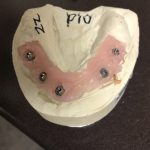
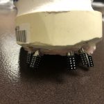
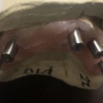
we will have all the libraries of the abutment from the margin and up available to you so you can pop them into the medit scan and easily identify the MUA in the mouth.
for the process to work in the traditional way, you would have had to place the mua’s, place the scnflags, image with icam. take off scanflags, place cylinders, scan with ios. then take off cylinders and then place healing caps. NOW, you can place the MUA’s, place scanflags, image with icam. export the stl and import it into medit. take off scan flags, BYPASS the cylinders, and just start scanning MUA’s in the mouth. With the AI feature, you will readily identify the multi unit abutments no matter how bloody the field is and if parts of the margins are buried under tissue. Of course, in the situation where the implant is super deep and the mua can’t stick its neck out, you will still have the option of popping the cylinders on. you will know which route to go as soon as you seat the MUA after surgery or uncovery
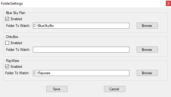
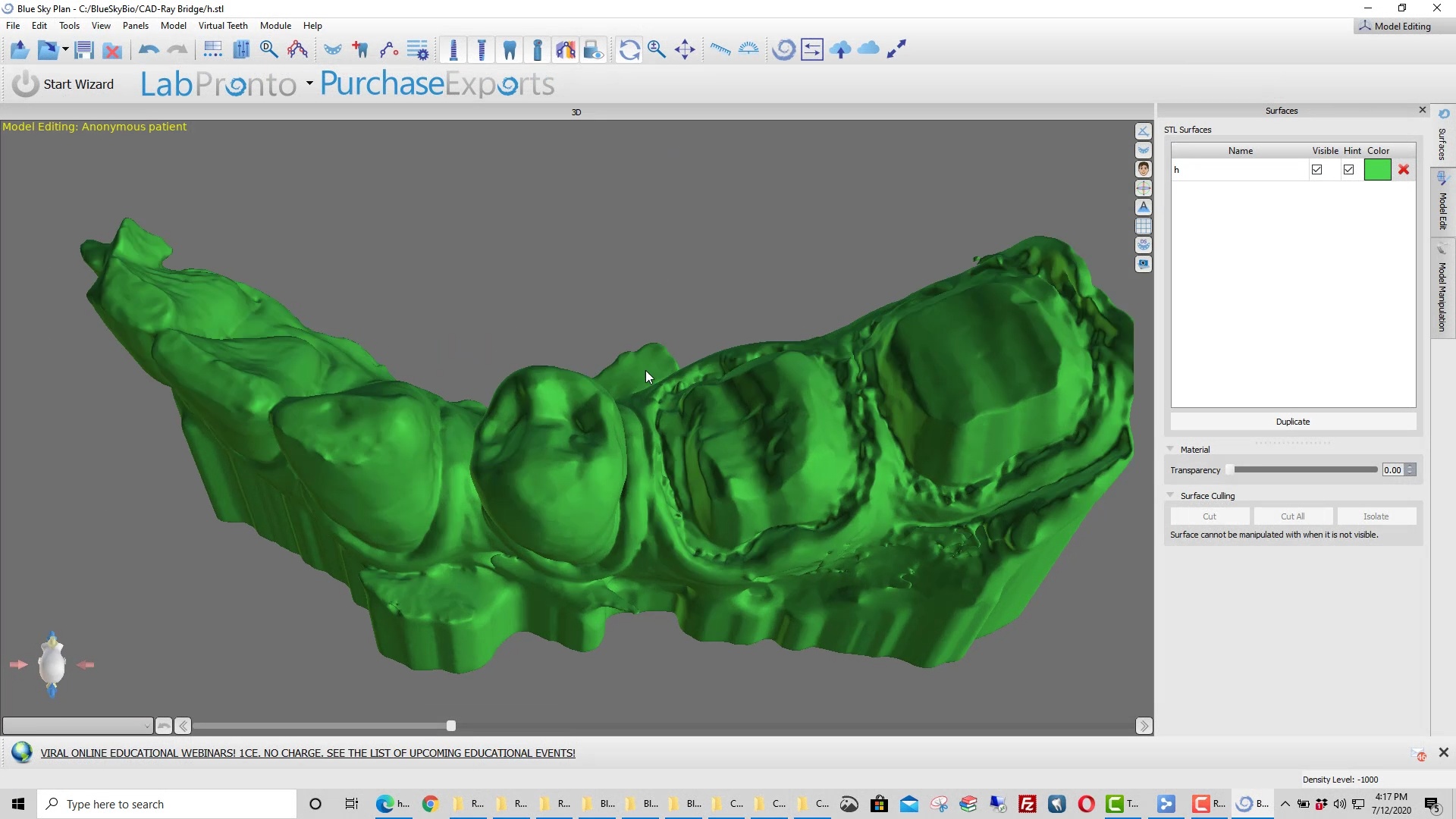
Thanks to Justin Shafer who created a script for us that allows you to export an stl file to a specific directory, where you create a subfolder for each program you want to run. Once the file lands in a subfolder the program is launched and the models are important.
Justin did this at no cost. The more you donate to his work, the more programs he can add to the installer. Some programs like Rayware allow you to import multiple files into one program whereas others launch a single program for each file, like BlueSkyBio. Contact the software designers to easily add commands line to accommodate your needs
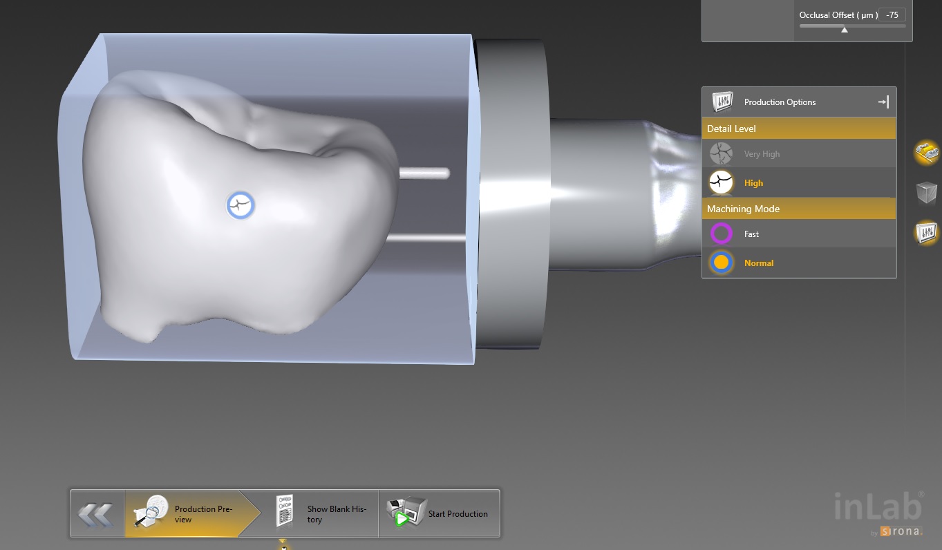
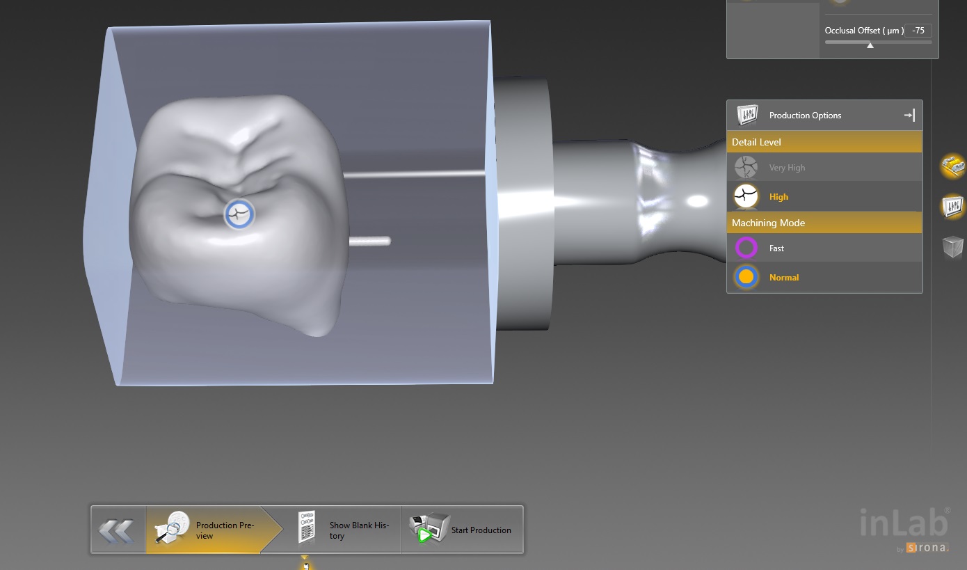
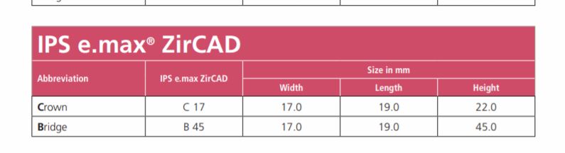
This molar’s suggested mill times with the MCXL are for either Size 12 or 14 blocks:
Sprue on distal in normal speed mode is 14:05 minutes, fast speed at 7:54
Sprue on buccal in normal speed is 13:48 minutes, fast speed at 7:46
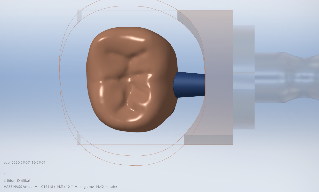
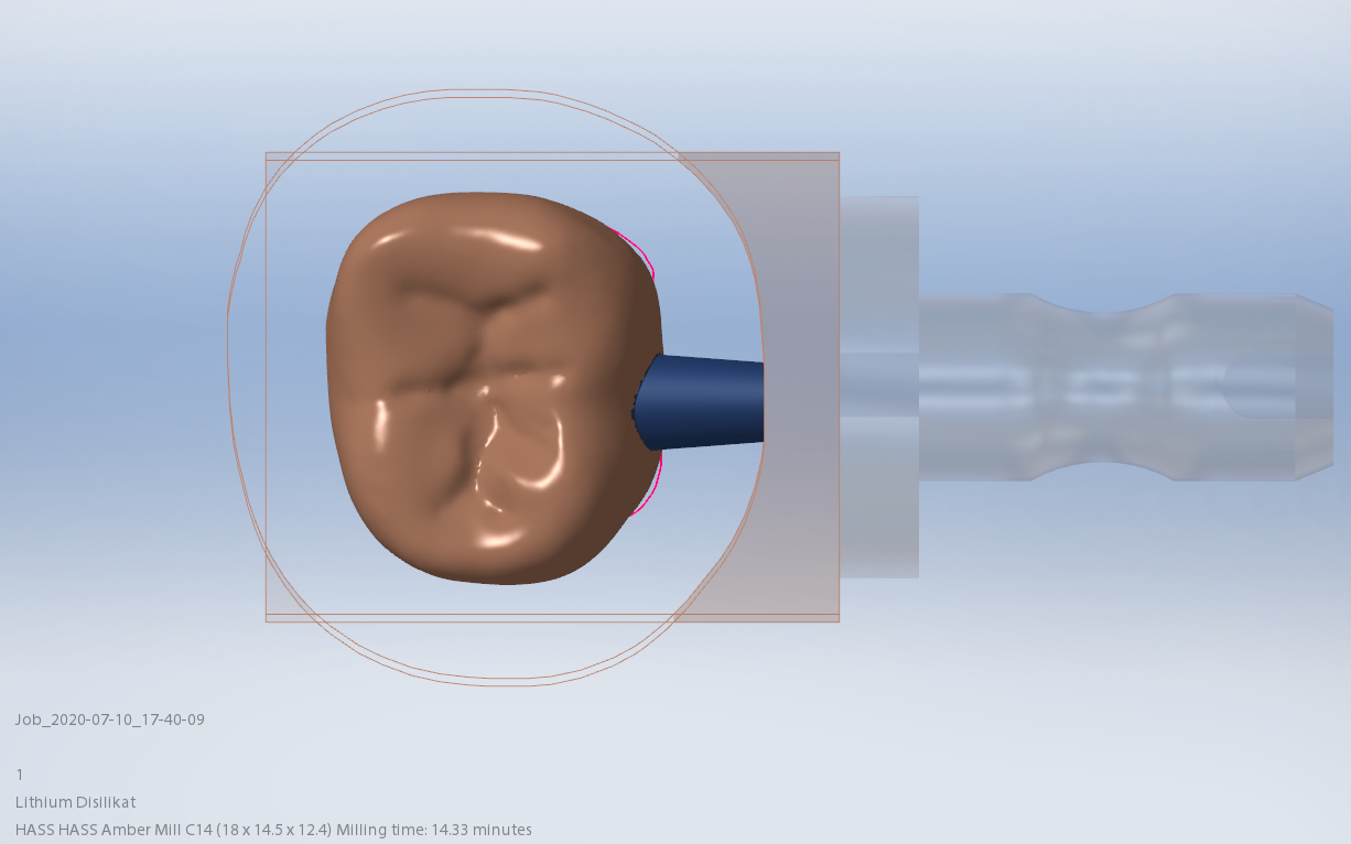
This molar would only fit in a size 14 block of Amber Mill in Imes Icore Coritec
Sprue on distal in normal speed mode is 14:15 minutes, sprue on buccal in normal speed is 14:42 and speed crown is proosed at 13:23
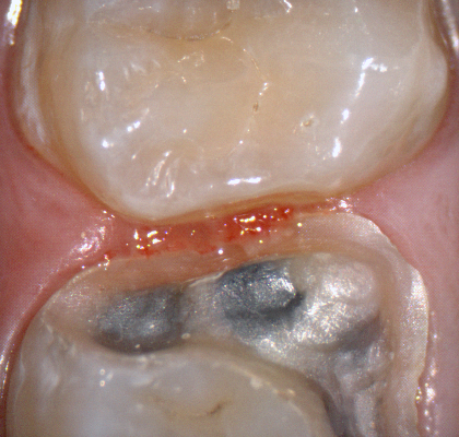
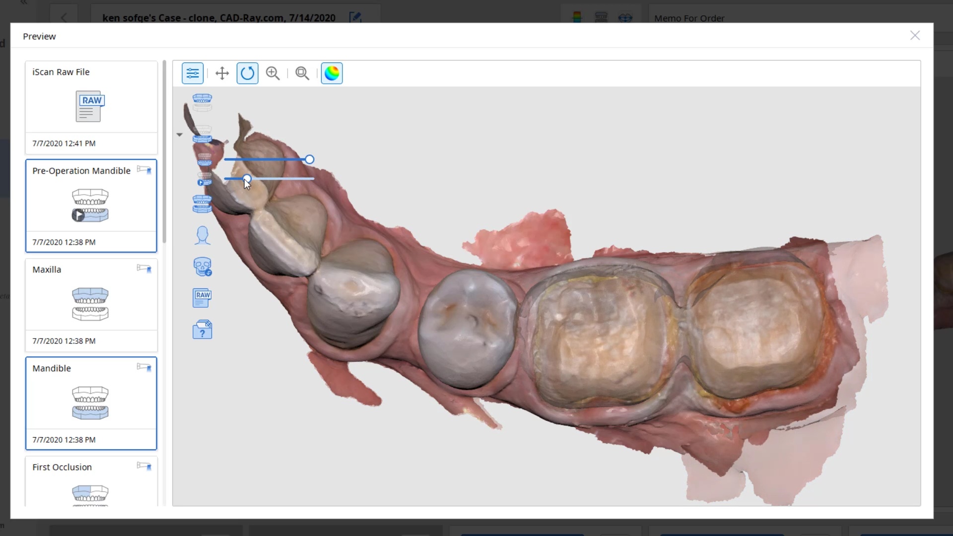
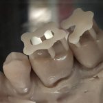
For our advanced users who mill in house or what to speed up their digital impressions we advocate taking advantage of digital dentistry’s unique features that allow you to take impressions over a period of time and segments, building larger models over different sequences and time. In this particular case we have two molars in the lower left quadrant that warranted replacement. The traditional method would be to prep both, isolate both, retract both, and take your final impression, but we will approach this as if there are two separate patients involved
Case Presentation on how to manage two crowns with a single milling machine
For the second molar, we will take advantage of the anesthesia time and capture the first bite, the opposing, the pre-existing situation and then crop out the preparation area digitally. Once the tooth is prepared, we will check for proper reduction. We will then take the second bite to verify the vertical dimension has not changed.
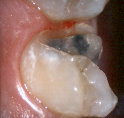
While the second molar is being designed and milled in the first case, we will launch a second window by cloning the first case. All the data remains the same and this time we crop out the first molar digitally and protect the rest of the arch. Once the first molar is isolated, it is digitally captured and then designed and milled.
image first molar while second molar is being milled
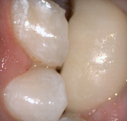
To manage the contact between the two crowns, there are many advanced applications. Here is a simple explanation of how we use the prep model from case 1 as the pre-op model for case two. Since the second molar in case 1 made contact with the distal wall of the first molar, when we design the crown for the first molar in case 2, all we have to do is make sure the distal wall is flush to the pre-op. This guarantees us a contact between the two. There are lots of shortcuts to this puzzle once you get the basics of digital impressions under your belt.
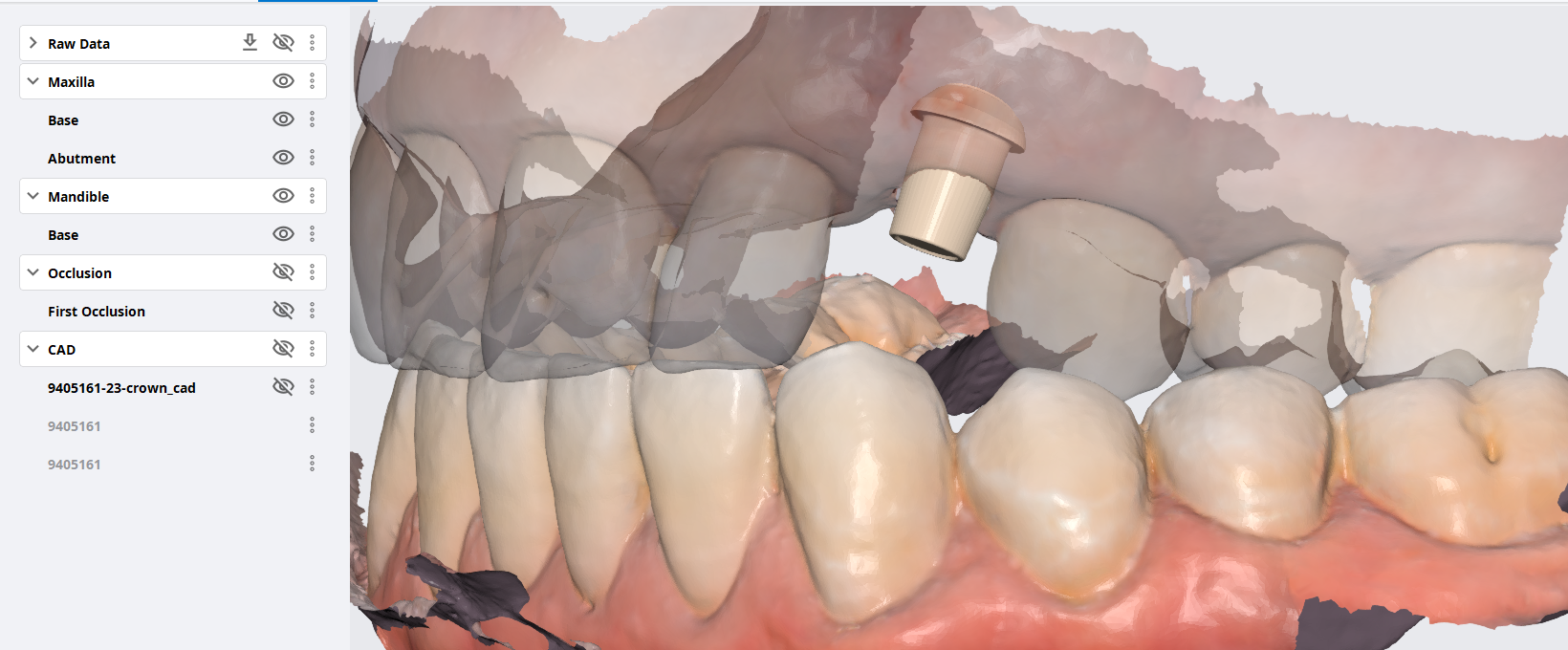
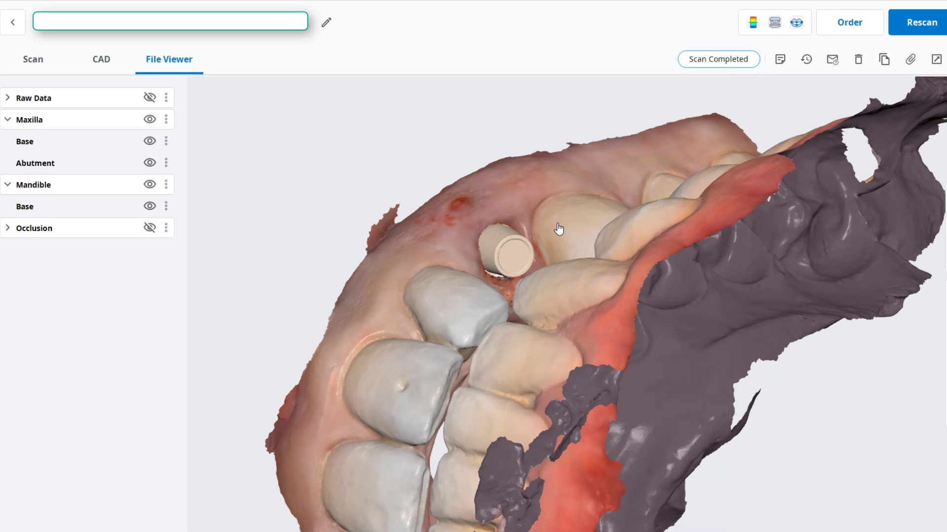
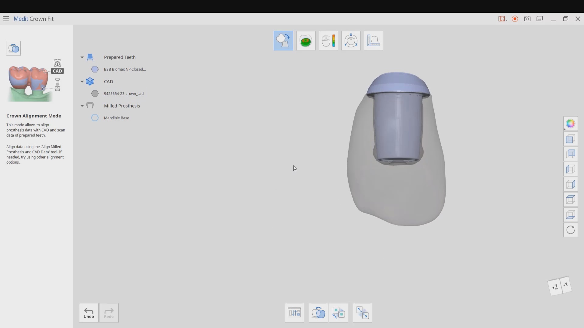
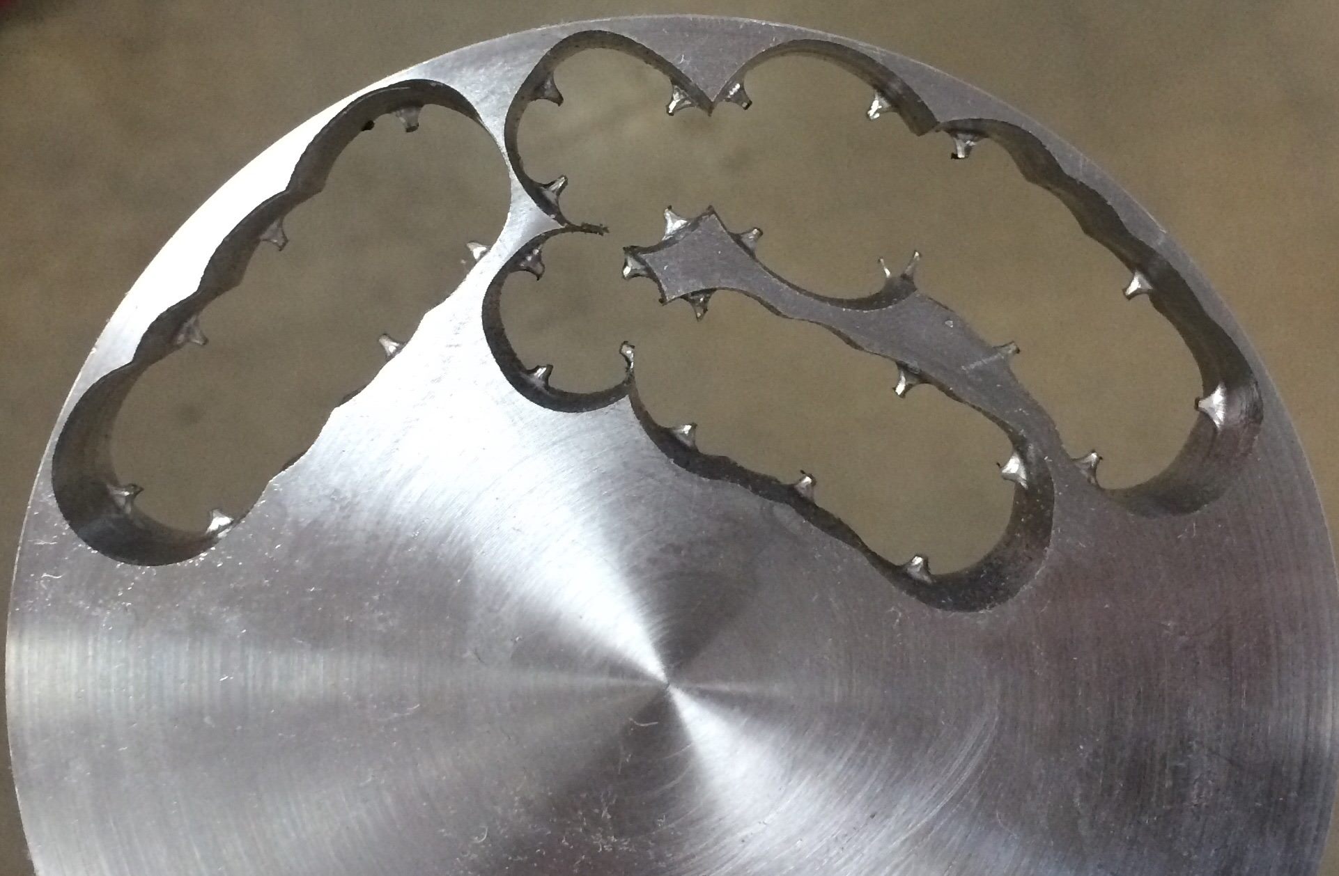
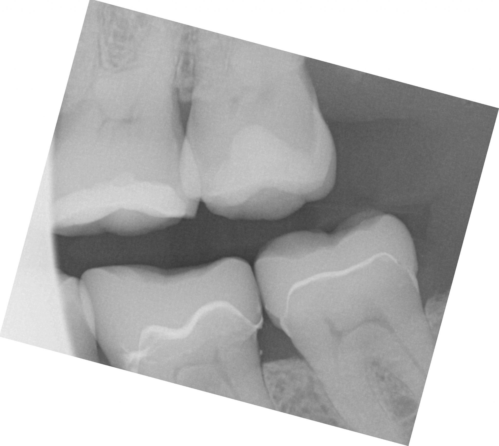
One of the big limitations of CEREC (a registered trademark of denstply sirona) with tibases and implant crowns is that it is limited to very few implant lines and the antirotational notch can just ruin your day as it needs to go into a specific location. You also have to deal with making sure the tibase is seated all the way and the scanbody is properly indexed. The one benefit is that you are dealing with just crown and bridge and you do not need to know implant position or timing at all when doing the design.
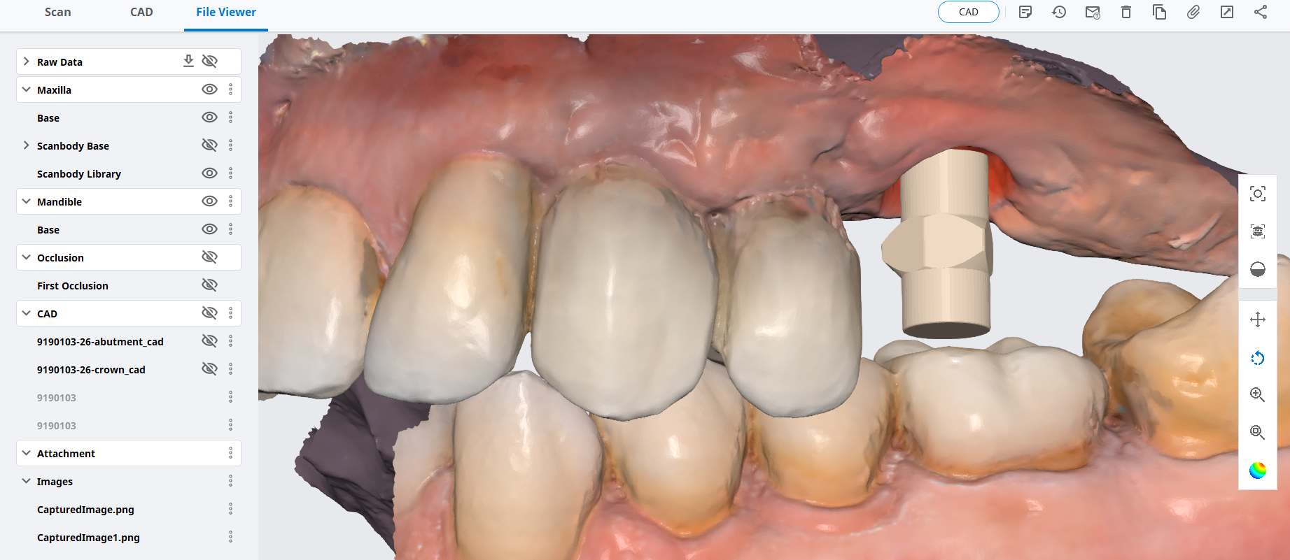
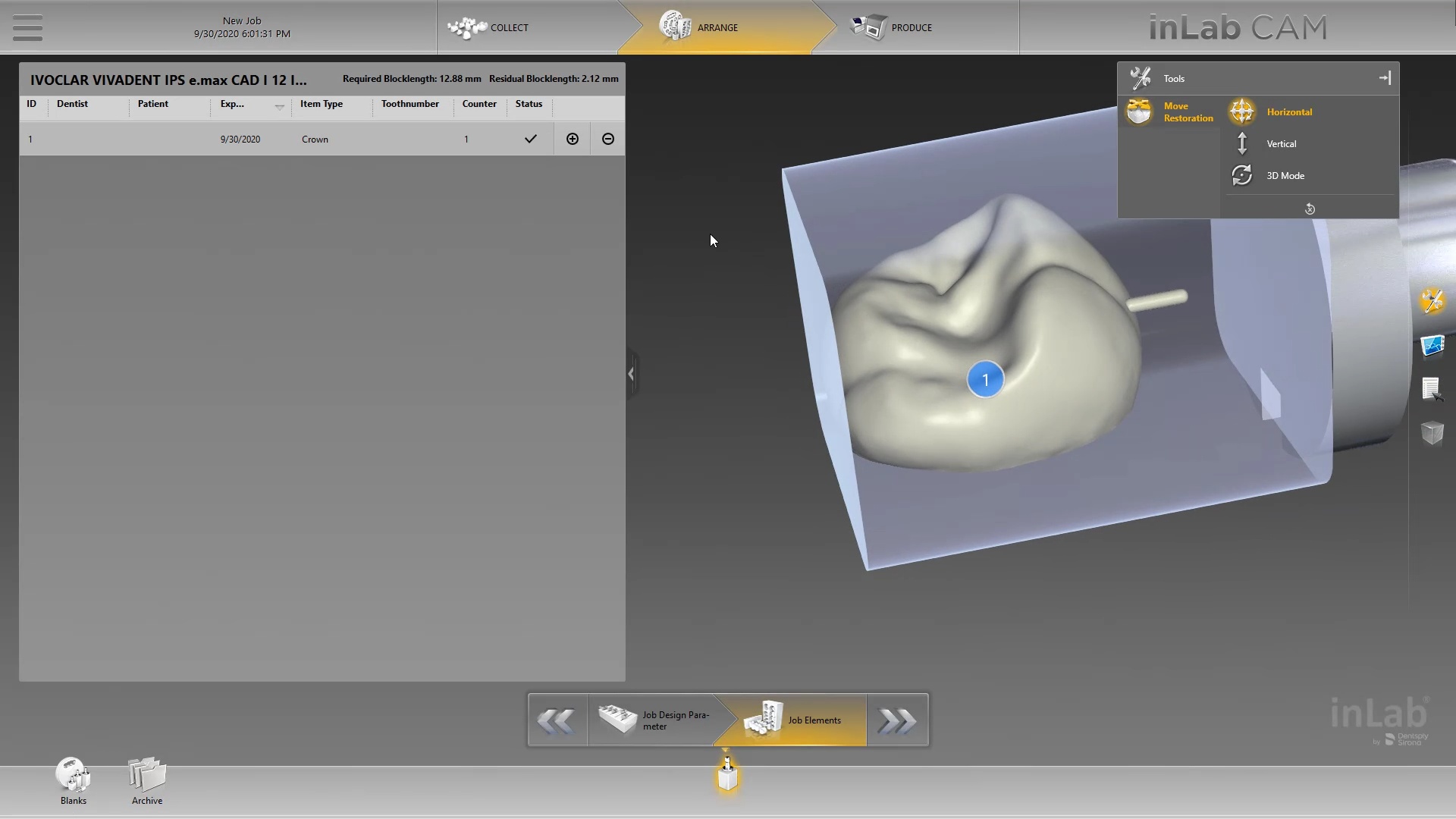
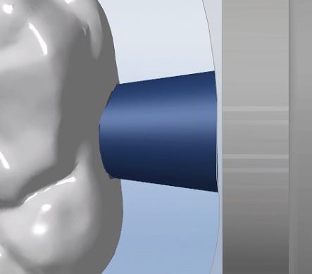
In this case, we demonstrate how we utilize the Medit i500 to capture a Tibase from Blueskybio, Biomax NP Conical Connection. Once the tibase is seated, we simply start scanning and then use the artificial intelligent implant suprastructure identification system to identify the location of the tibase. This in essence allows you to capture your margins OUTSIDE the mouth and you don’t have to bother with imaging the tibase, which is highly reflective in the patient’s mouth.
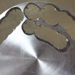
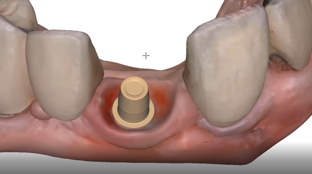
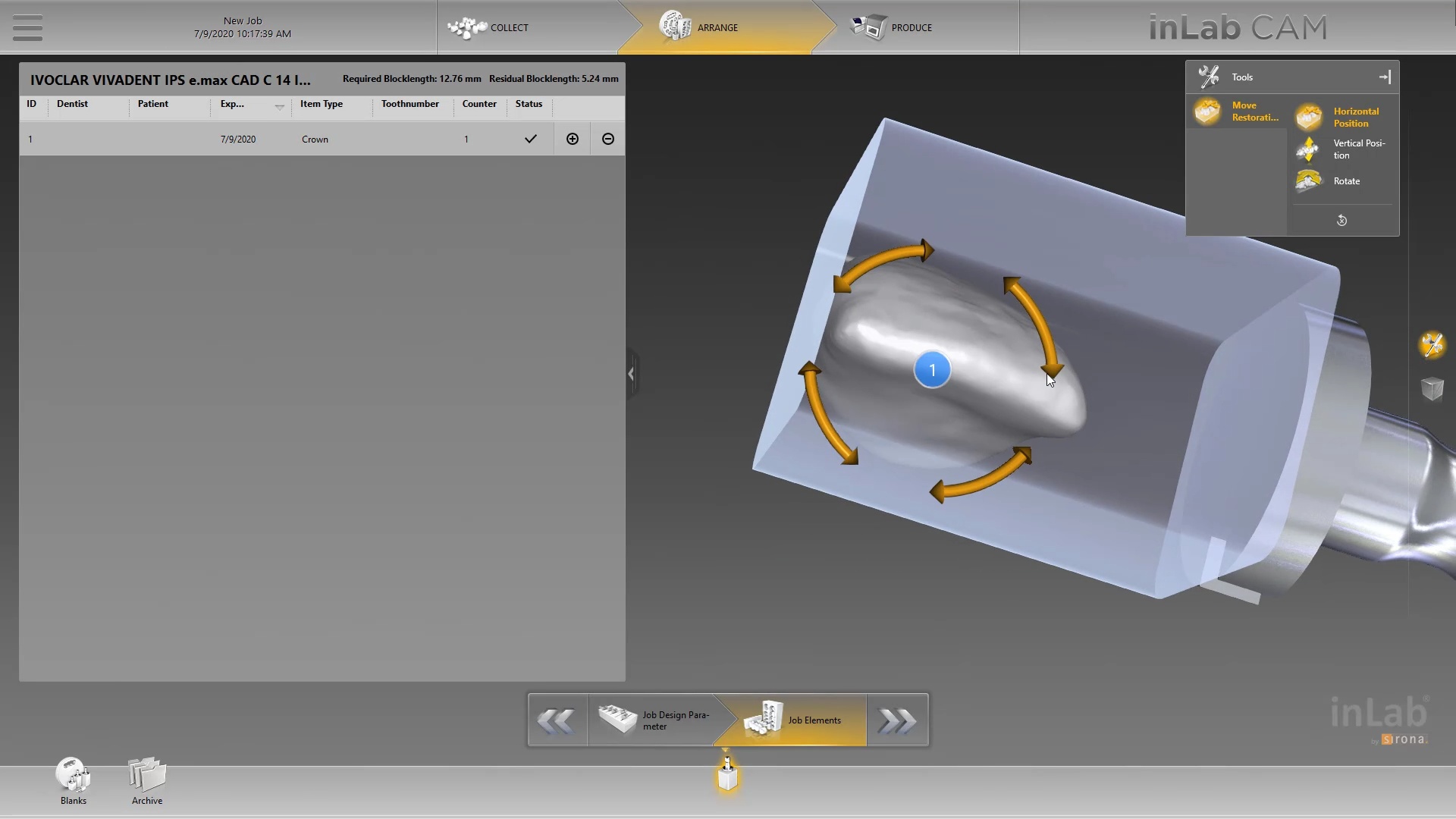
Once processed, you can then modify the tissue digitally and gain access to the tibase margins. You can print the model if you want and manufacture the restoration. In this particular case, we took the design to the CEREC mcxl inlab cam, nested it, and milled it out to demonstrate how we can image with one device from one manufacturer and fabricate a restoration by another company’s manufacturing machine. But the single greatest benefit is that you can place the sprue wherever you want.
IMPORTANT NOTE: The Tibase that you use MUST be wider than the drill milling the intaglio and the sprue must be thick enough to handle the milling process.
Once you understand how the digital workflow goes, you can image with one device, design in another, and then either print or manufacture with yet another device. Here we mill a sectional stent with the cerec that was designed in Blueskybio plan, although printing makes more sense because it is less wear and tear on your drills
For our coritec users: new users often mislabel restorations in the Rx form that leads to a lot of trouble. like calling a crown and onlay or vice versa. this can lead to all kinds of trouble
first sign of trouble is if the two purple lines don’t define the borders of the the restoration. sometimes it is missing, other times it is off the restoration. so always double check this step and usually the missed nomenclature is what causes the trouble.
the next problem people have is that the default setting for the sprue design is poor. it makes the sprue thicker at the mandrel than the restoration. this creates a crevice that the drill can’t get to. this leads to quick drill breakage as it tries to drill into that space (red circle). it is easy to set change these settings so the drill “flows” with the design of the sprue and you get a lot of use out of it. it’s annoying to do this manually so a subsequent video shows you how to change this by default.
another problem is the offset. the last video shows the distance from the restoration to the mandrel as 2mm. the drill is 2.5 in diameter. if you set it at 2, the calculation doesn’t allow enough space for the drill that also breaks it off. set it at 2.7 or 3 and it will last you a long time.
two subsequent videos will show you how to create your own blocks and change their orientation, so you can fit a taller design into a smaller size block
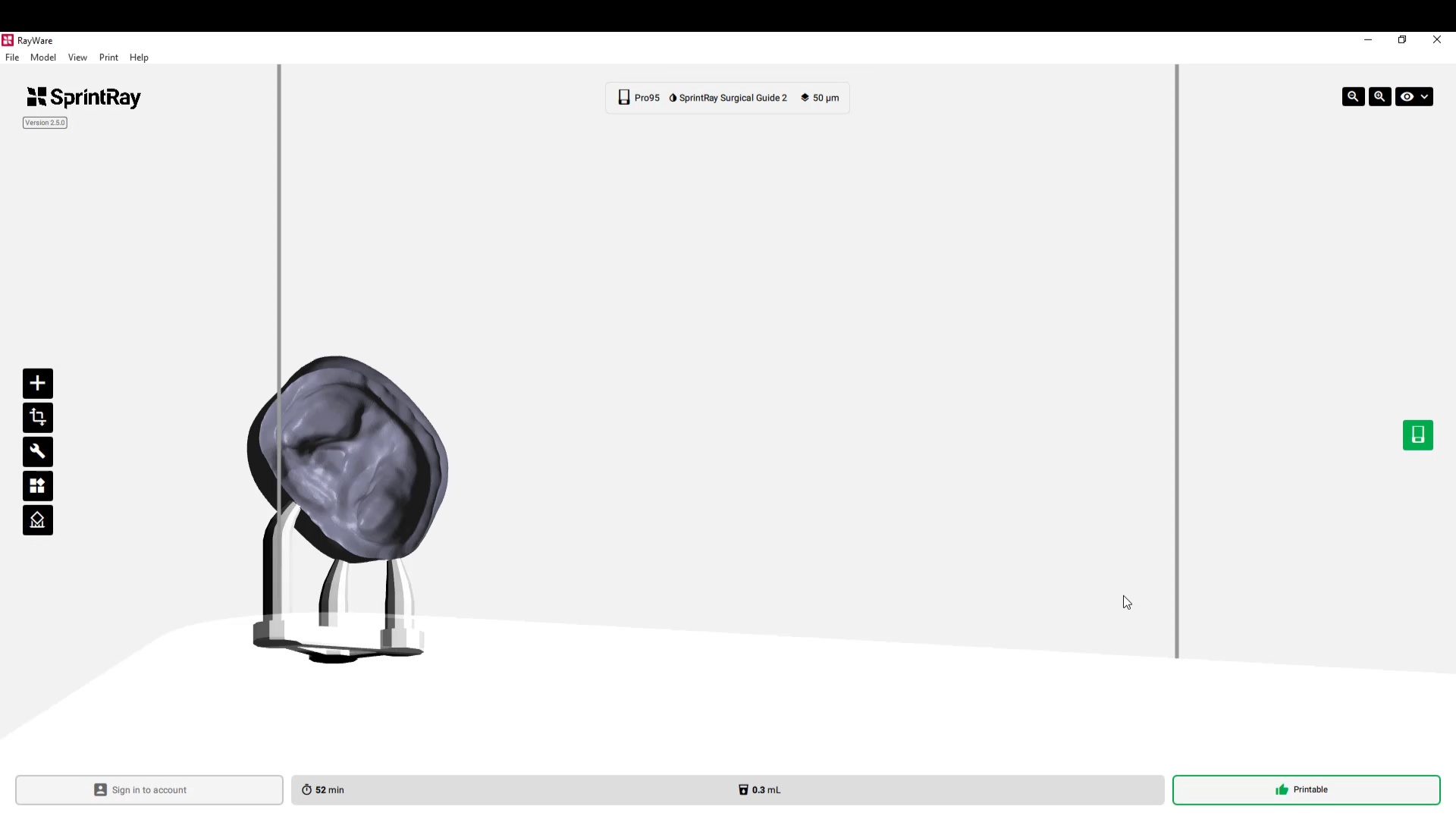
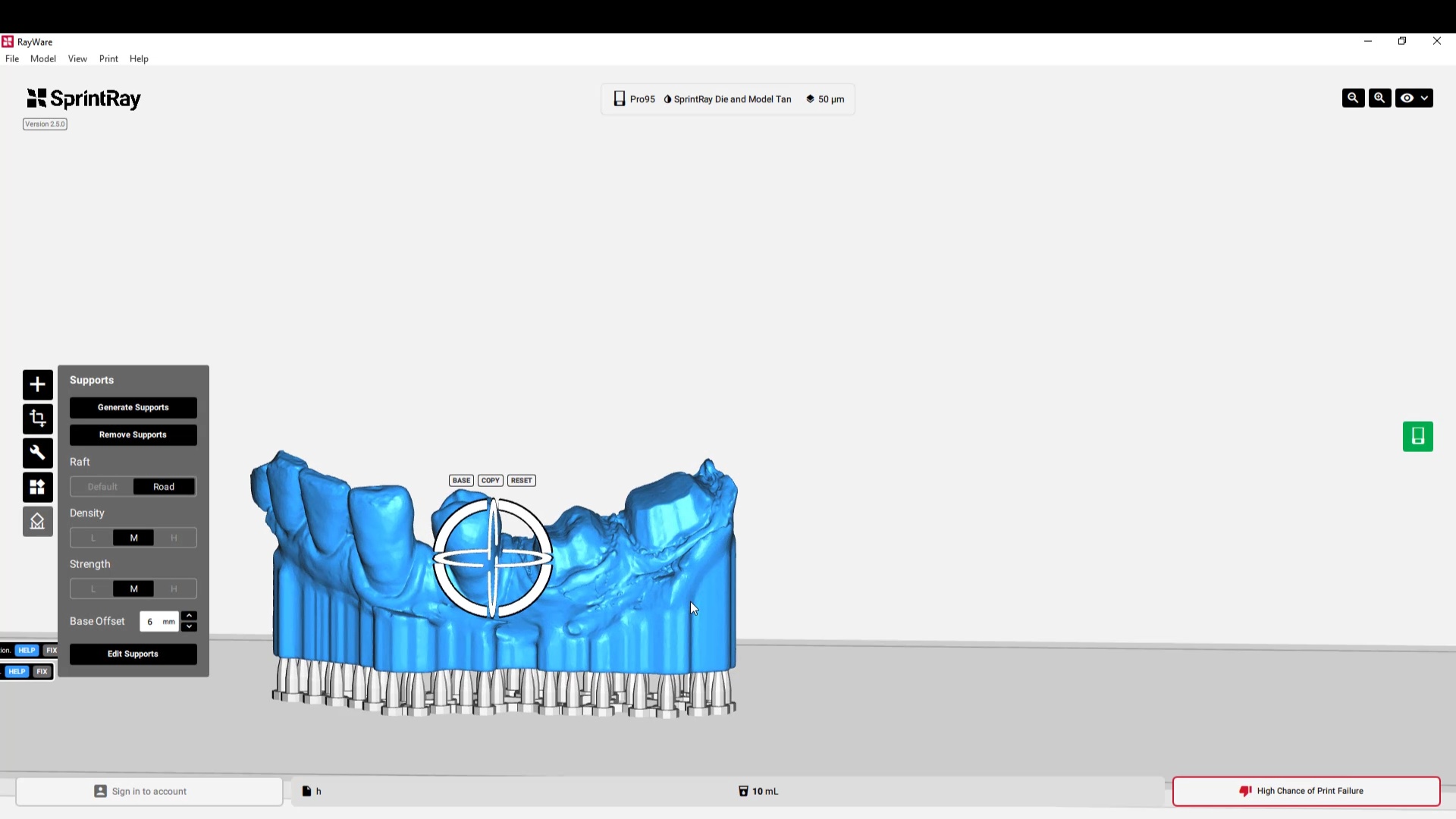
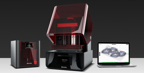
Last Thursday, we announced RayWare 2.5 – the software update that makes your SprintRay 3D printer new again. Watch the announcement here to learn about Pixel Toning, Parallel Slicing, Ludicrous Speed, and much more. Full-Length Video: https://youtu.be/Cix1DNNQdYY Download RayWare: https://sprintray.com/software/ Request a Dental Model Sample: https://store.sprintray.com/samples
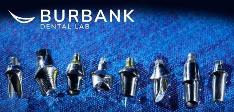
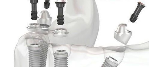
If you place enough implants, you may find yourself in need of a prosthetic part that just isn’t manufactured by anyone. For example, you may have a hybrid case on Bicons and for some reason you wanted to restored them with Multi Unit Abutments (MUA) and photogrammetry, yet there are no parts manufactured for such an endeavor. The problem is complex because a manufacturer needs to mass produce these parts and get them past regulatory matters.
Some have found a simple solution, which is to have the parts custom made specifically for the implant. If they need the MUA part before the procedure, they just send a digital or physical model into a lab that can custom make the part. The lab itself needs a prescription form on the lab analog. Since it is custom made, you have direct input on how tall you want the height of the margin, how much you want to displace the tissue, how much would want the restorative head angled, etc..
Most people will order a variety of them to address any situation on the same model and keep it in stock. What’s important to realize is that from the restorative standpoint, all your CAD software needs to know is the location of your abutment margins. It doesn’t care where fixture is and how the timing is lined up in the arch form. As long as it knows where the margins are, you can proceed with the design of the prosthesis.
Contact Andrew Seddler to send a digital or physical model and an Rx to get your custom made MUA’s