


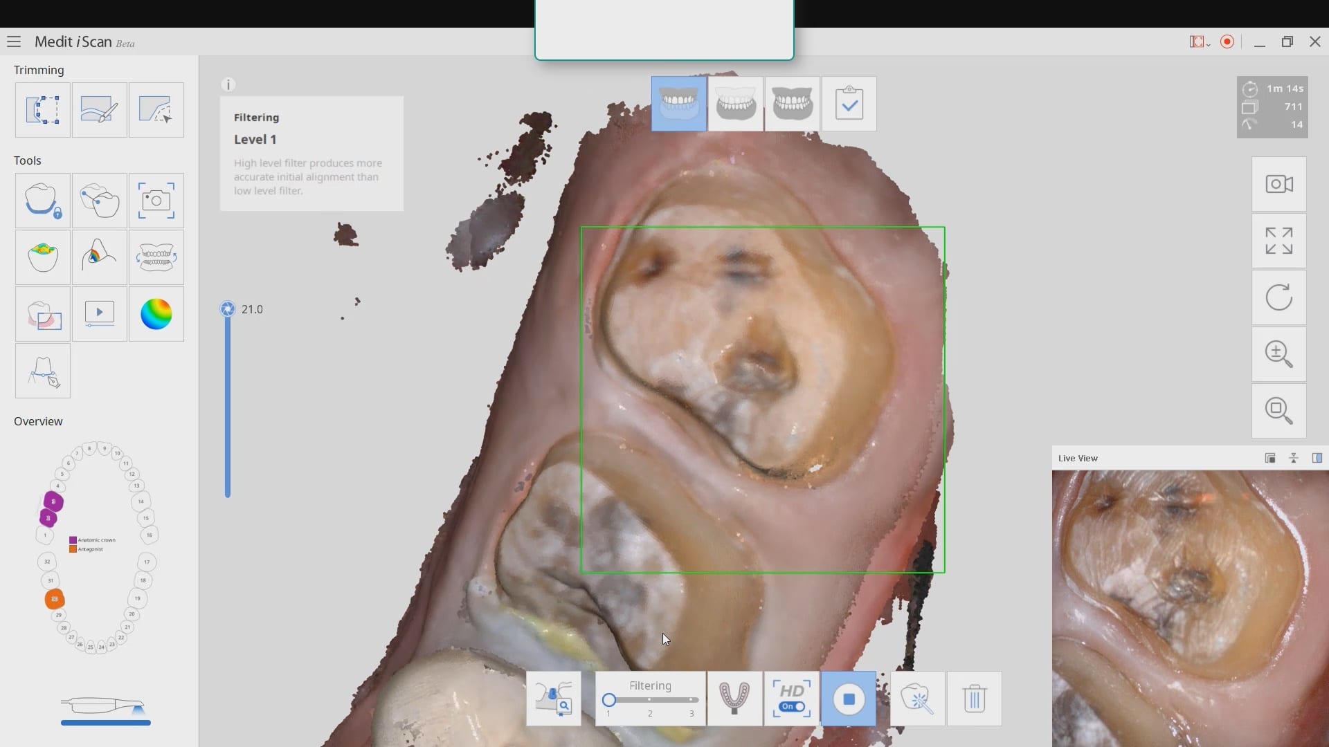
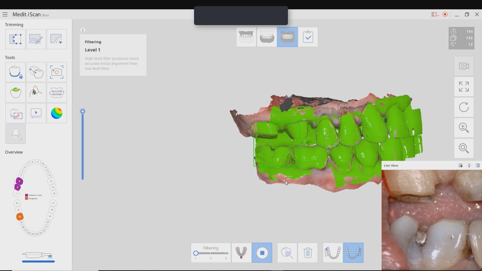
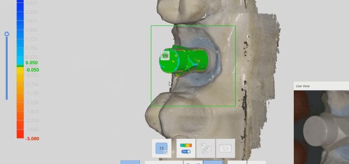
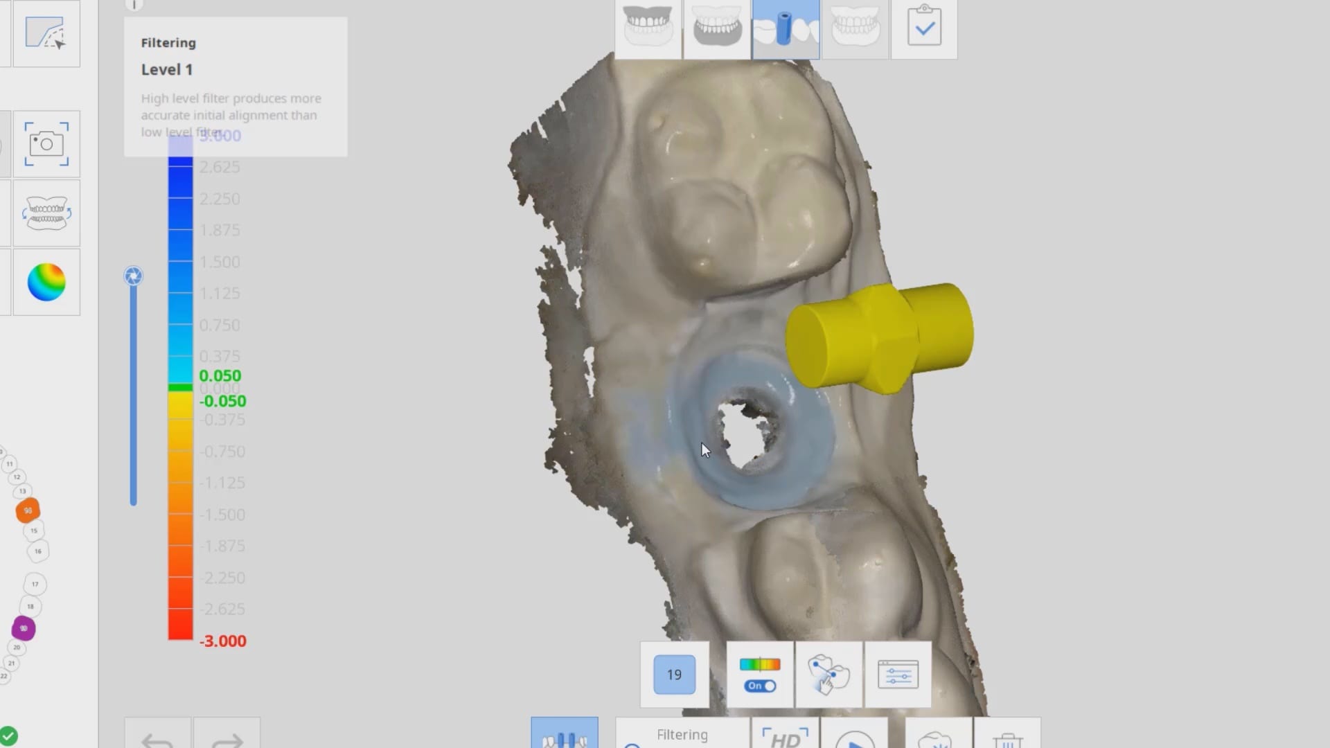
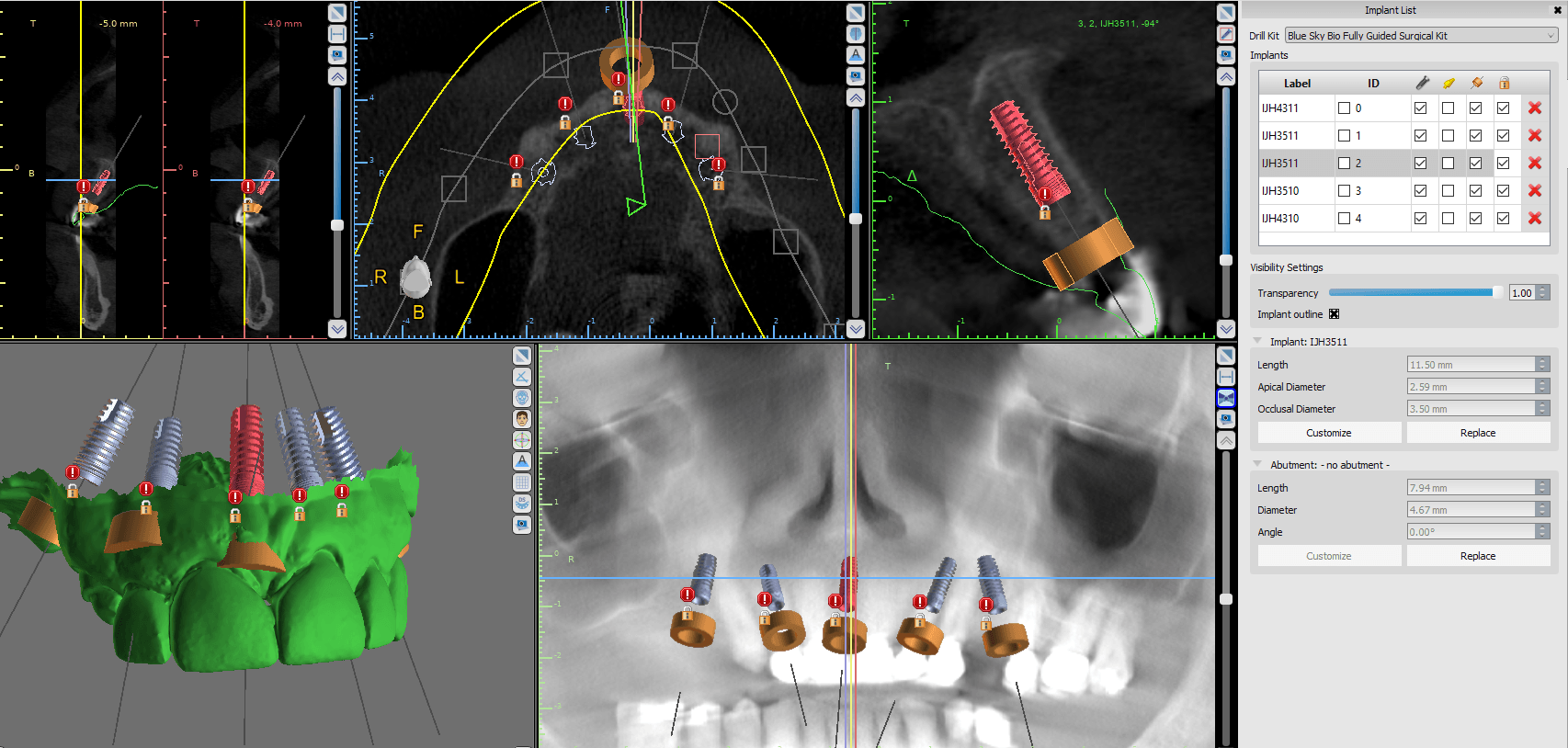
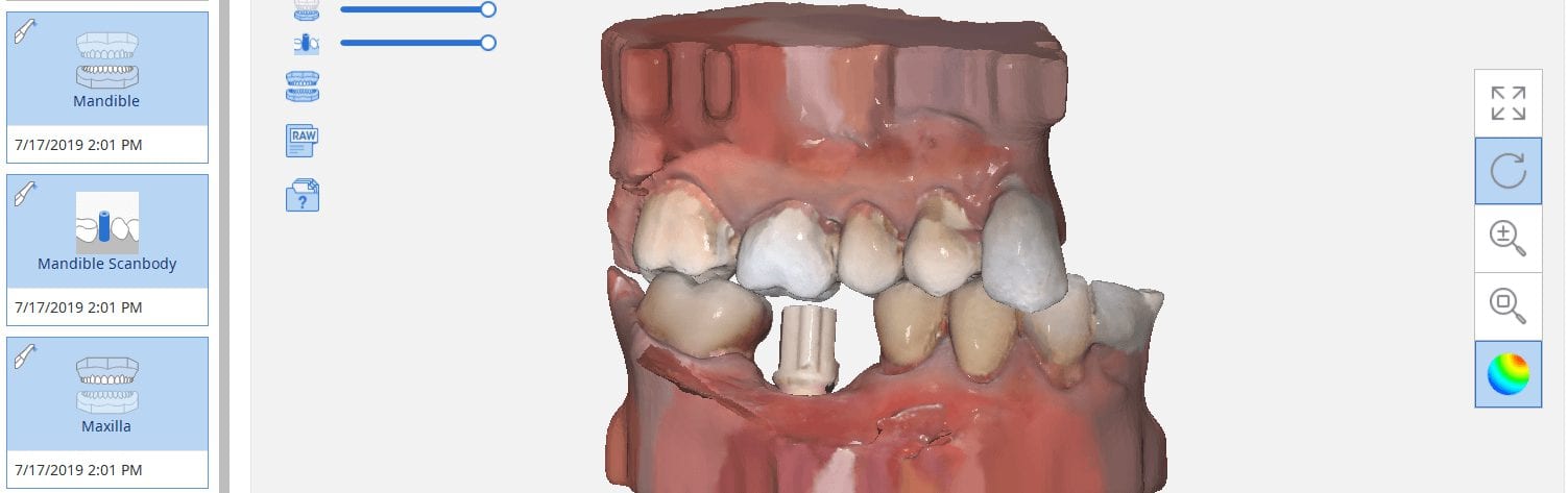
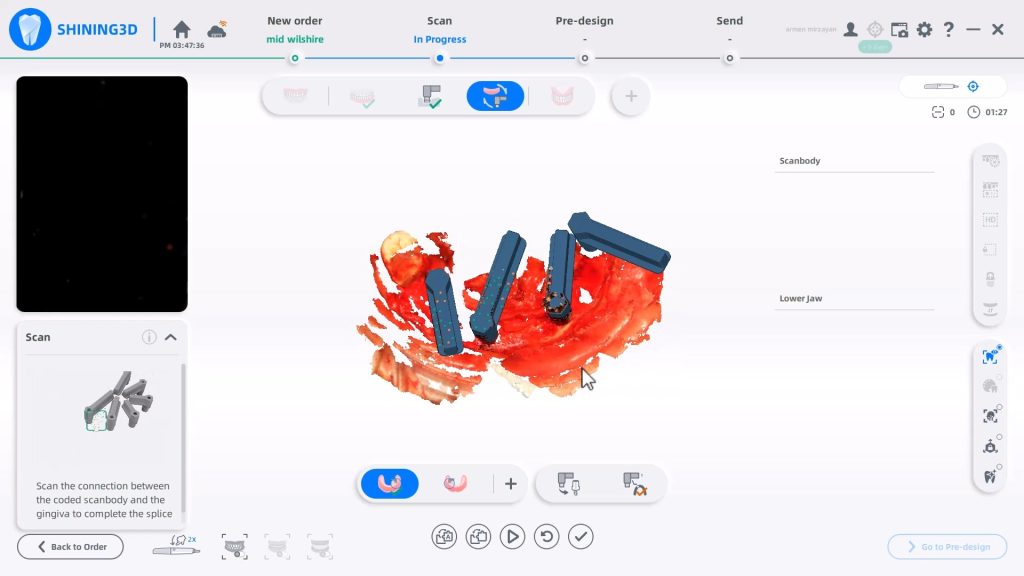
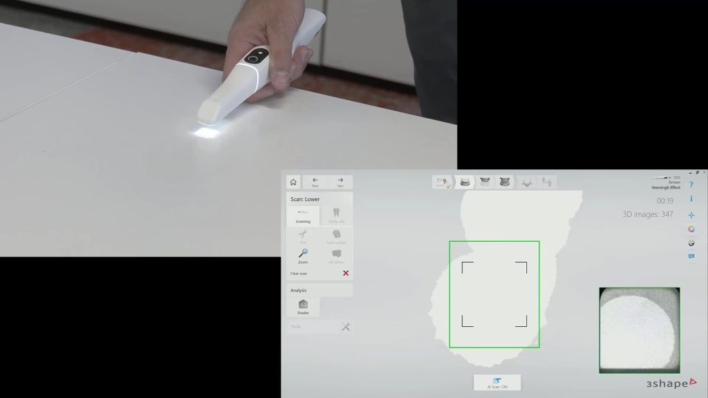
A new feature coming to Medit i500 is the automatic detection of scanbodies while you are imaging. In this clinical case, two implants are placed in the lower left quadrant in a fully guided fashion. Spacing limitations and proximity to vital anatomy did not allow for proper parallelism. This can create all kinds of headaches with analog dentistry where the trays can inadvertently lock in the mouth of distort upon poor up.
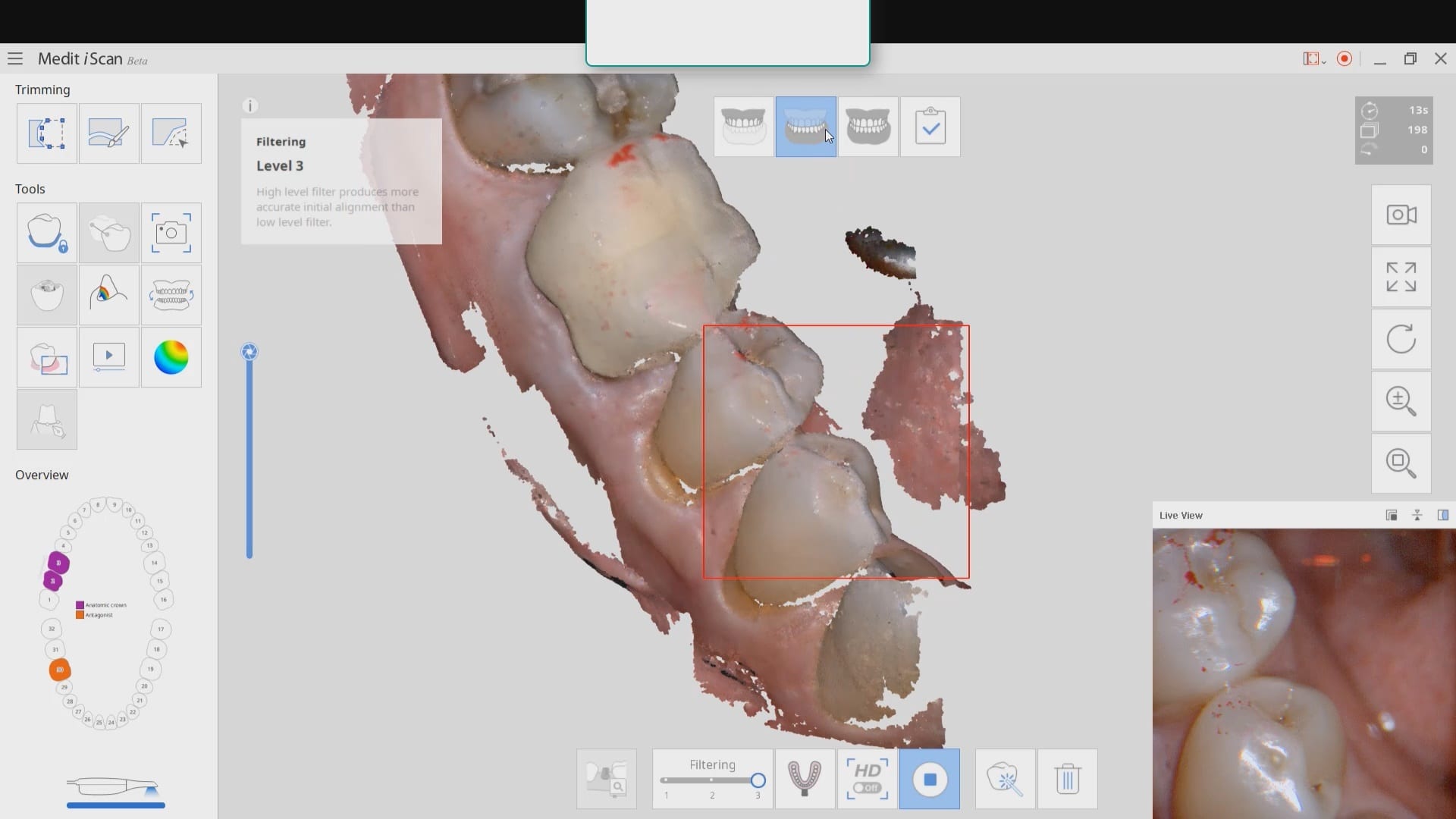
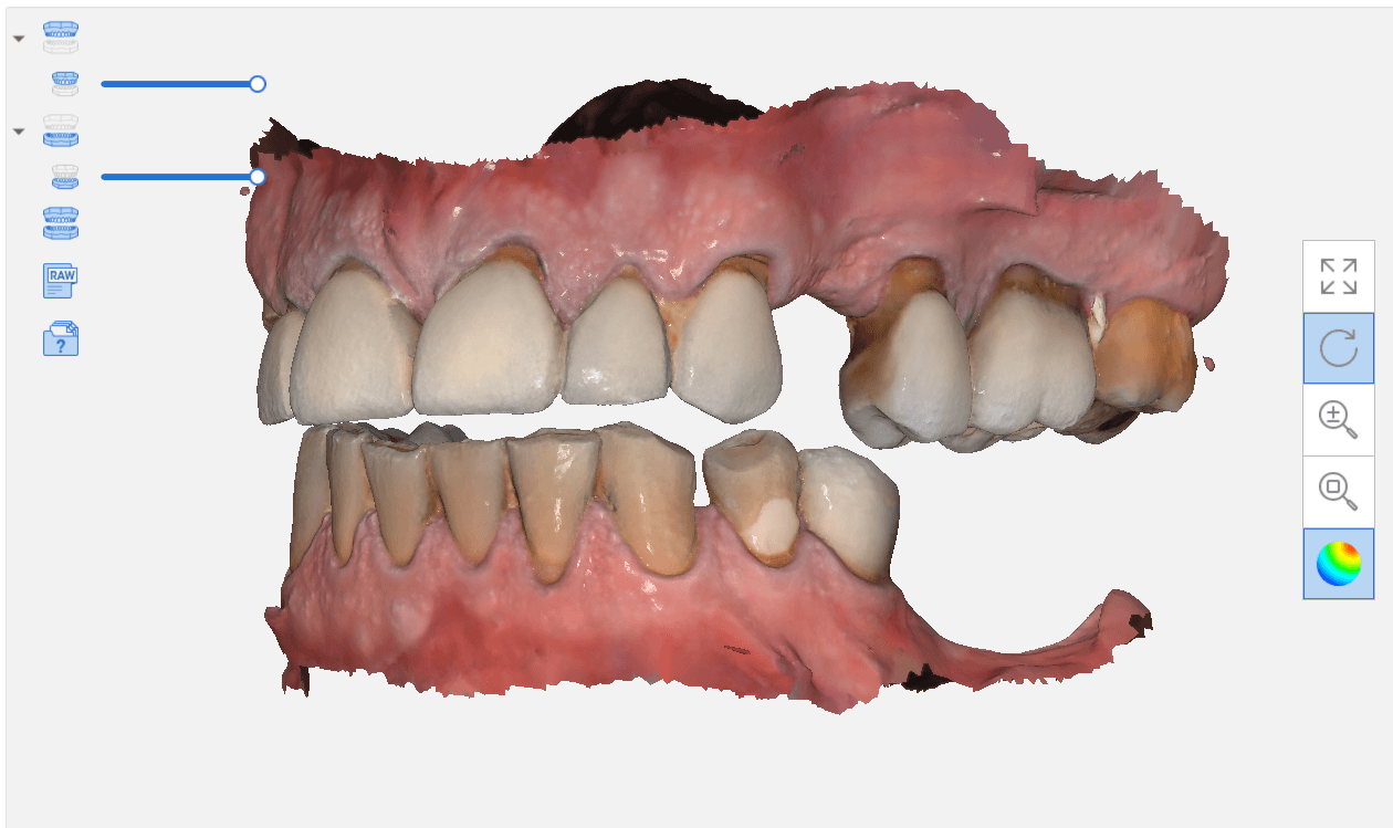
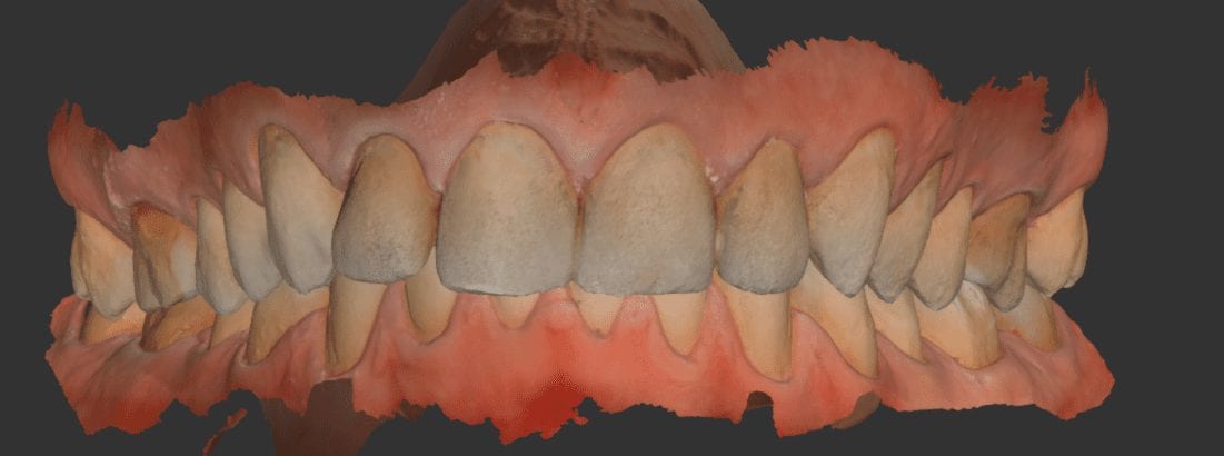
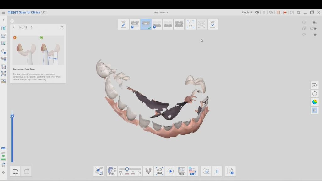
With the digital approach, you can scan the gingiva, the arch with easy access to adjacent contacts, and then the scanbodies themselves. What is great is that you do not disturb the primary stability you just achieved by placing physical forces on freshly placed implants.
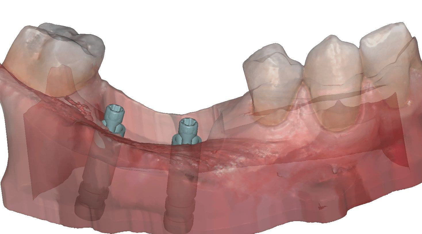
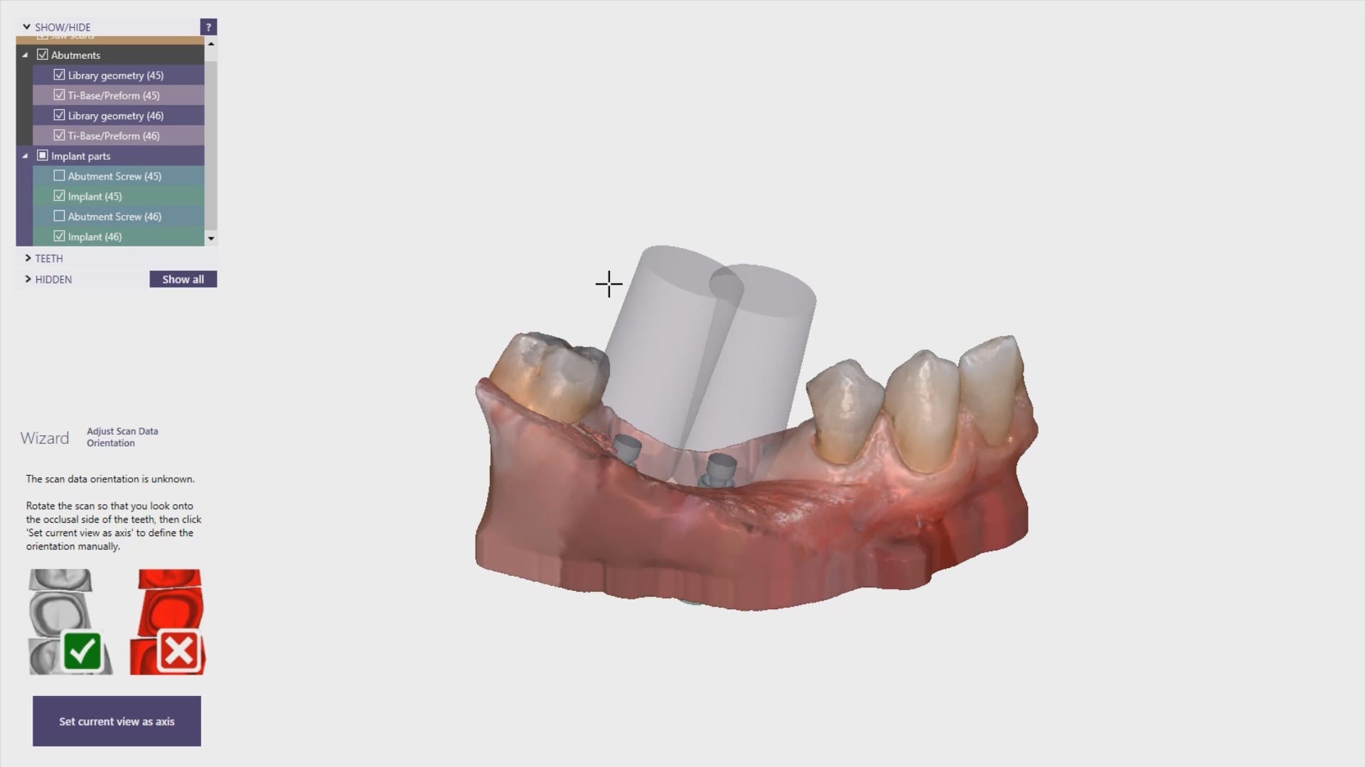
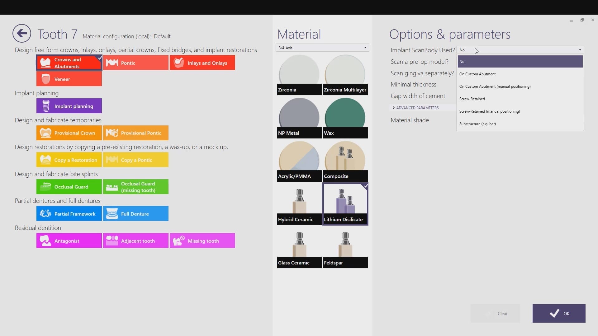
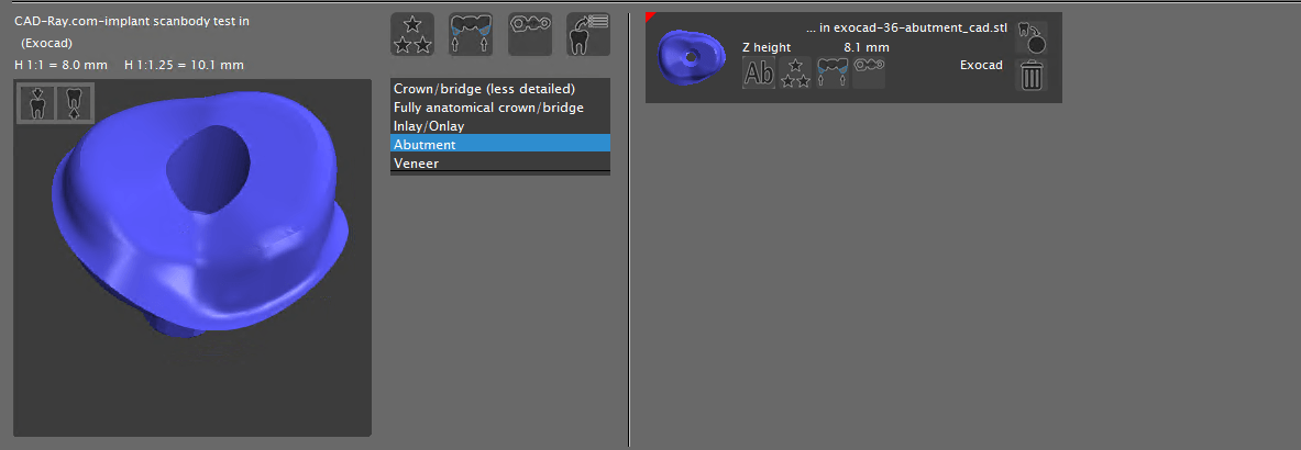
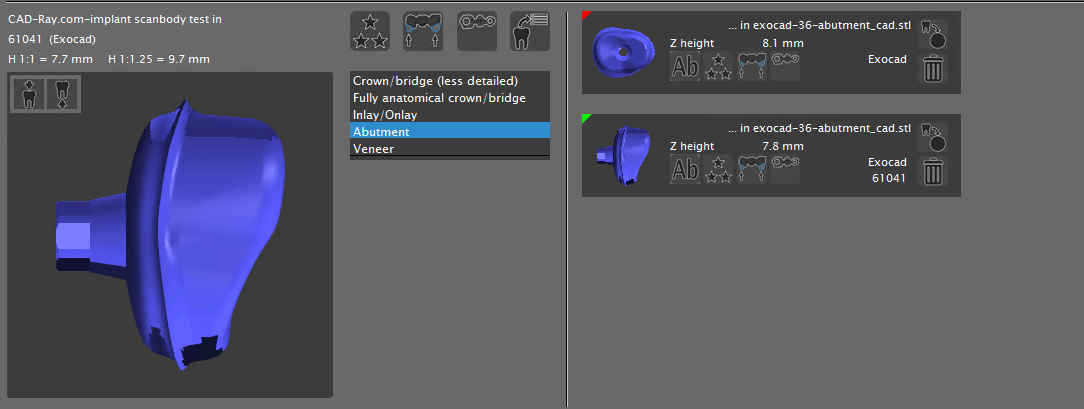
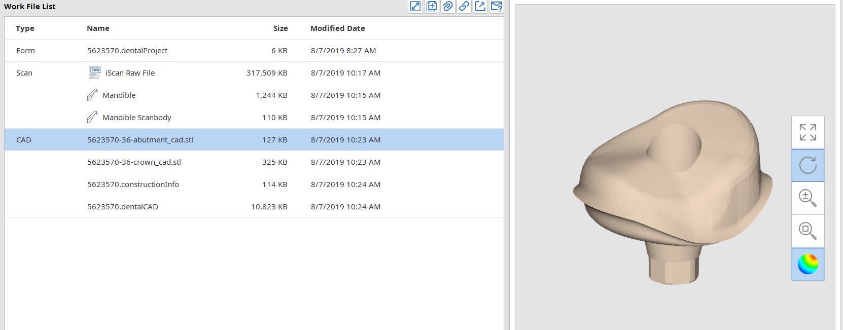
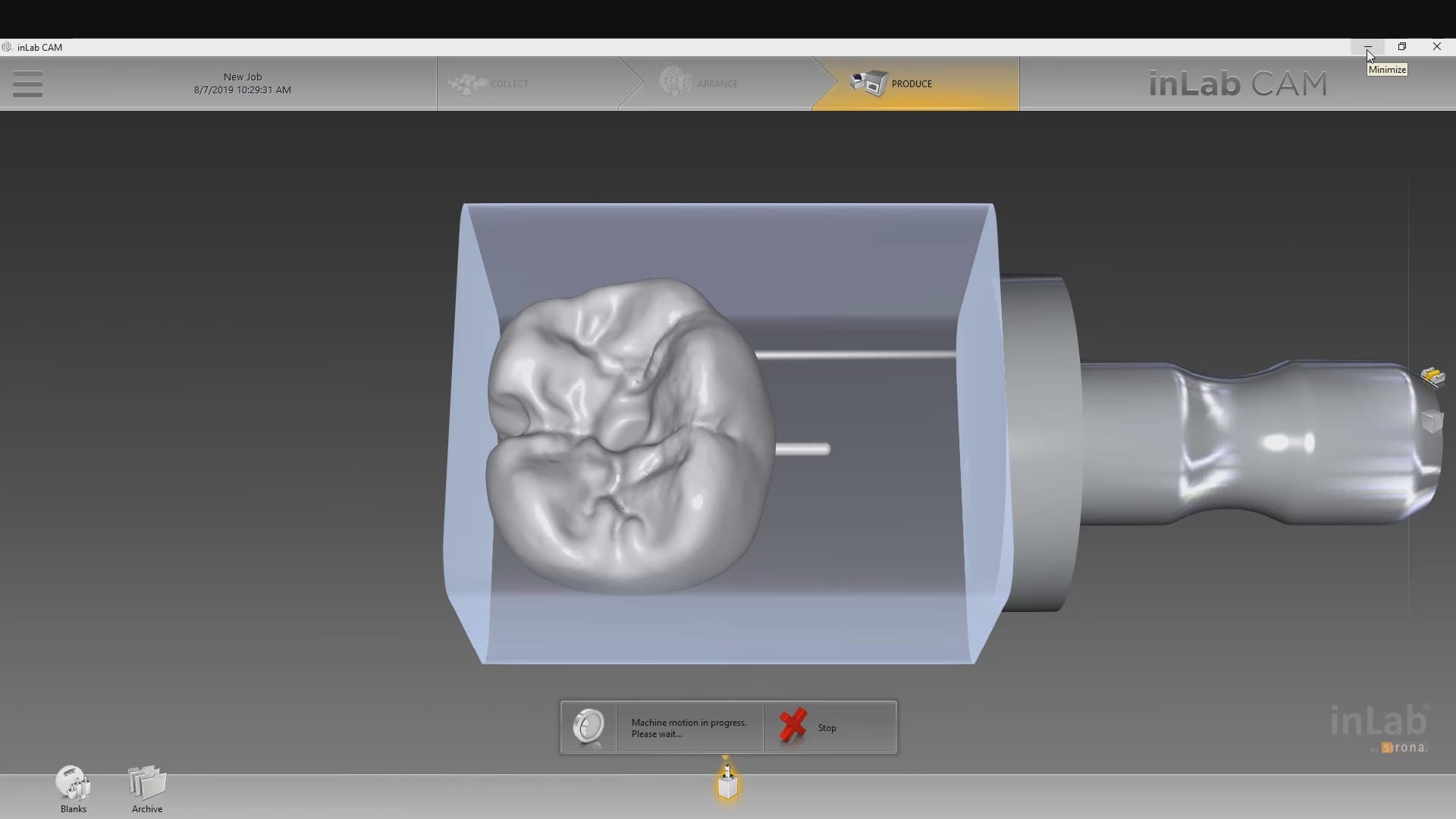
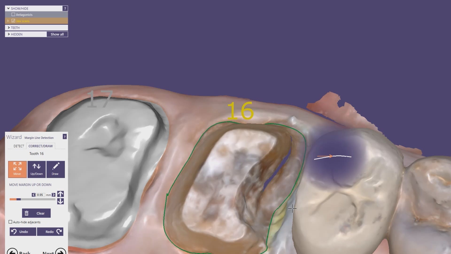
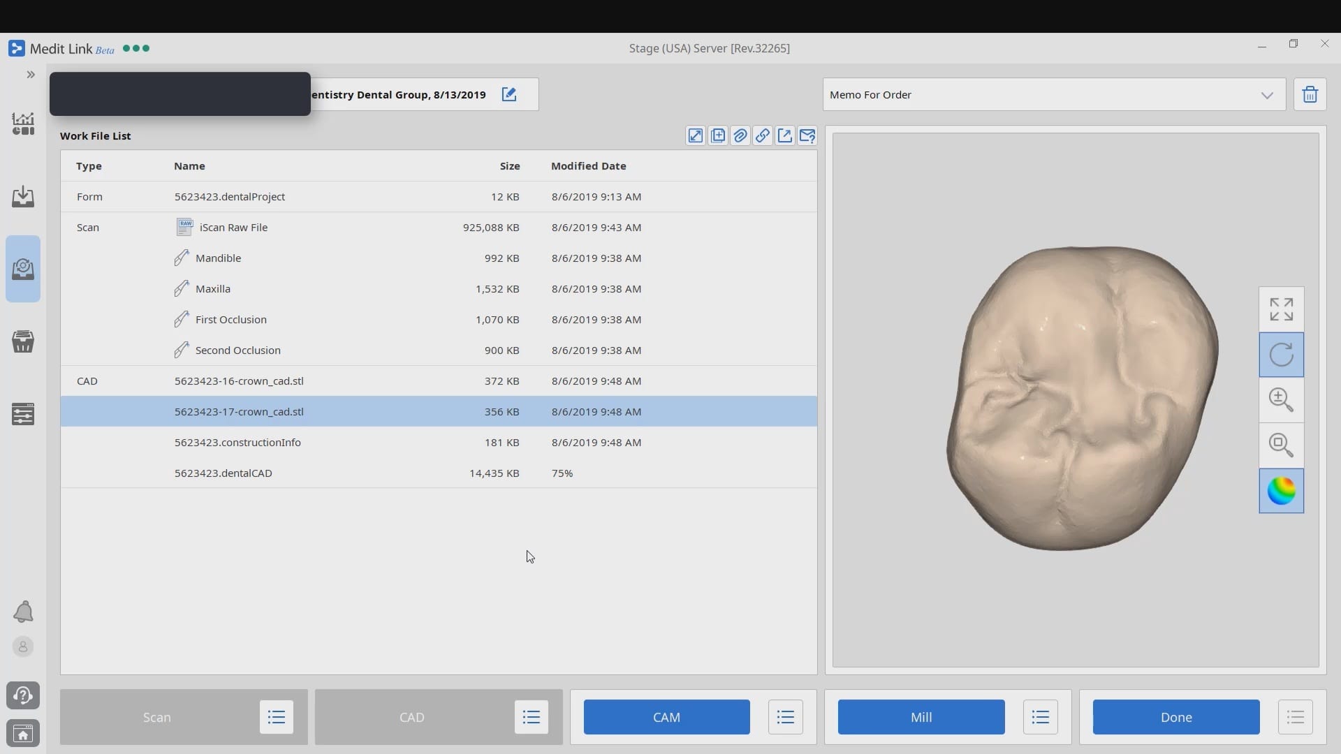
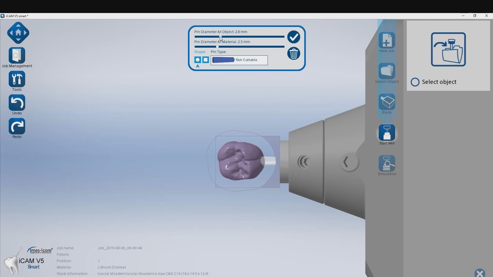
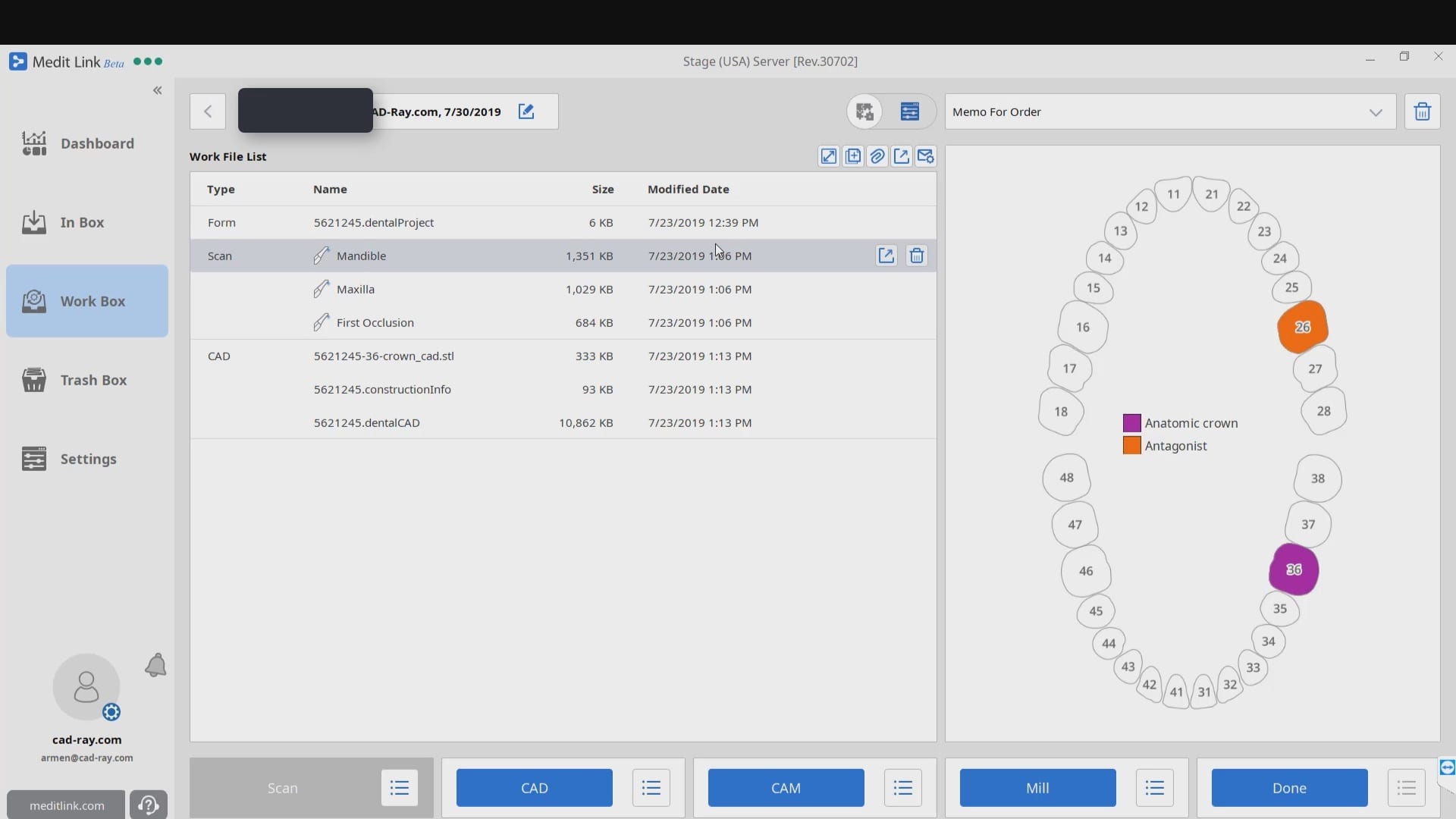
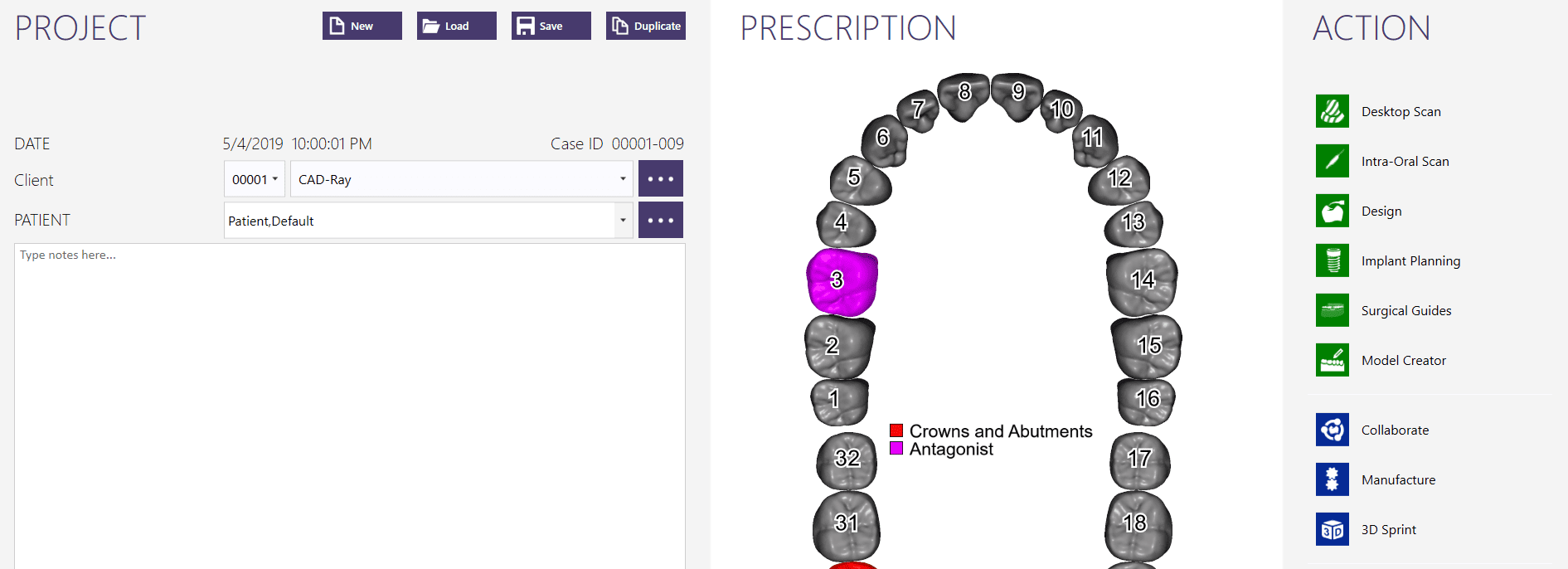
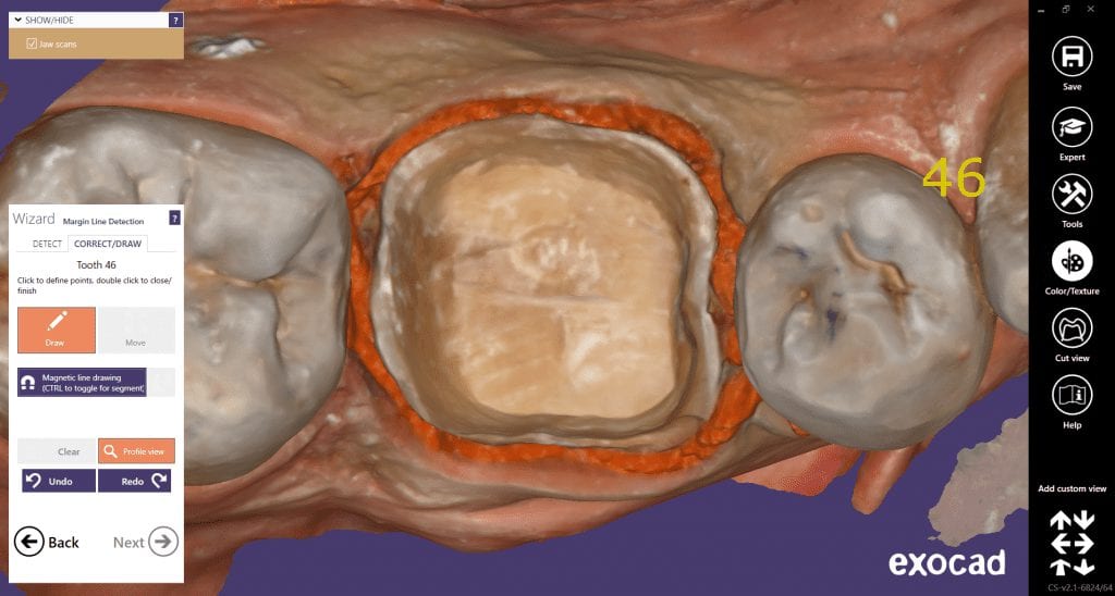
Once the images are captured and the scanbodies are identified, we launch exocad and the data is not only automatically imported into the Computer Aided Design Software, it also plots the fixtures in the correct position and identifies their location and timing so you can proceed with the design of the custom abutment and / or tibase restoration.

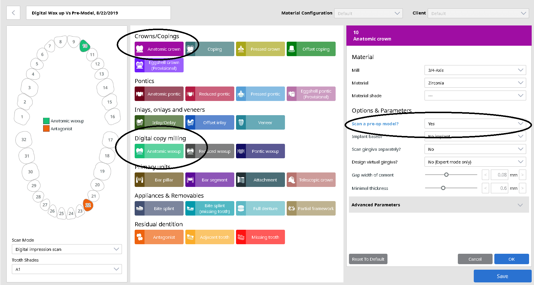
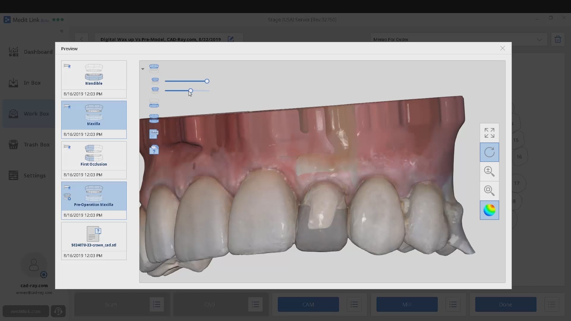
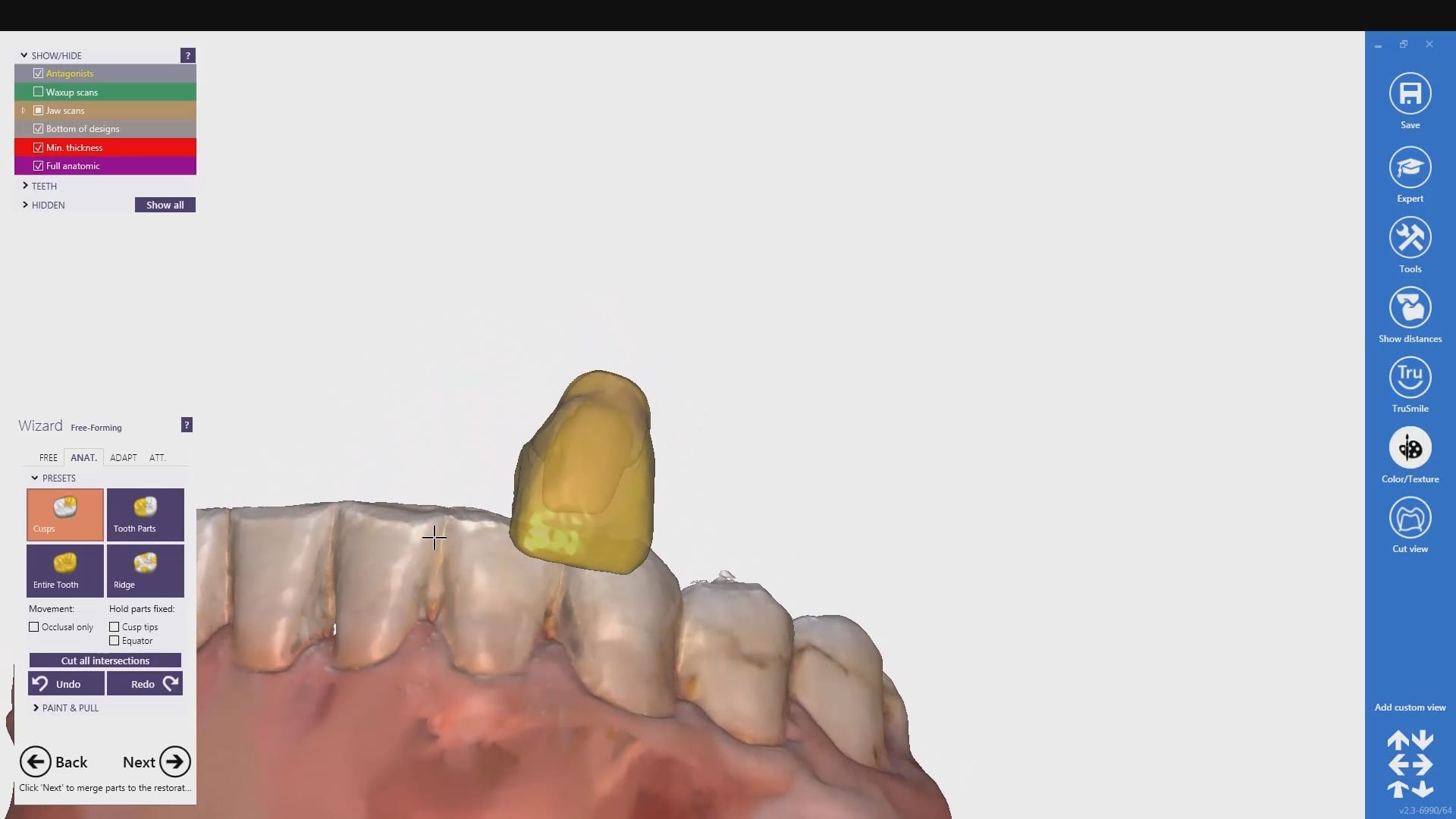

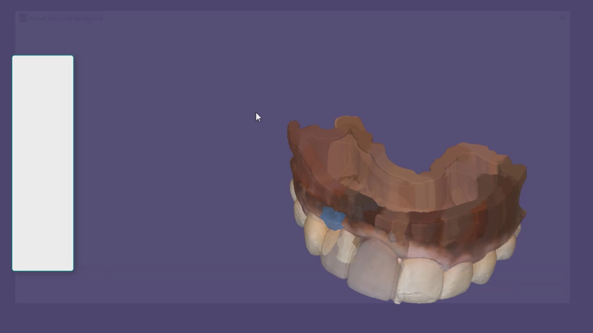
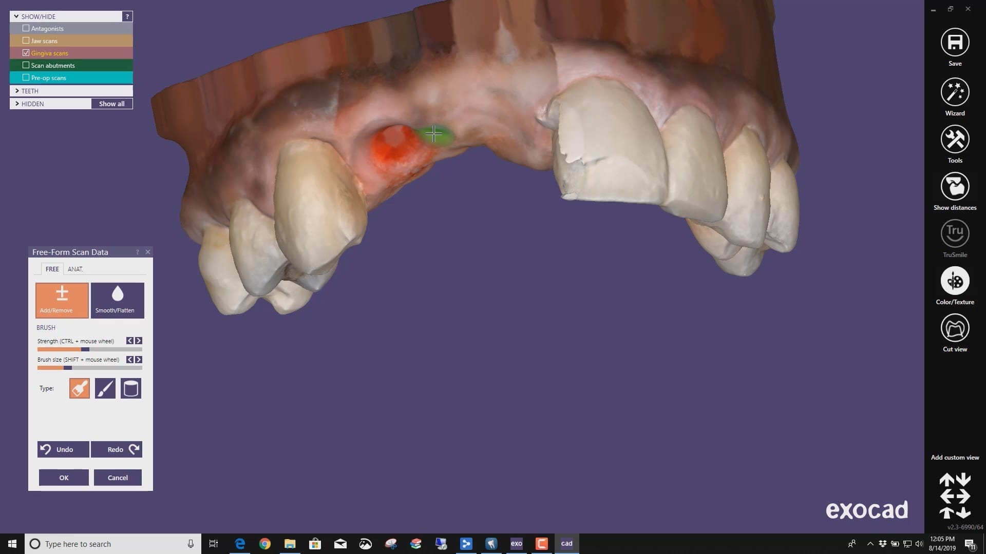
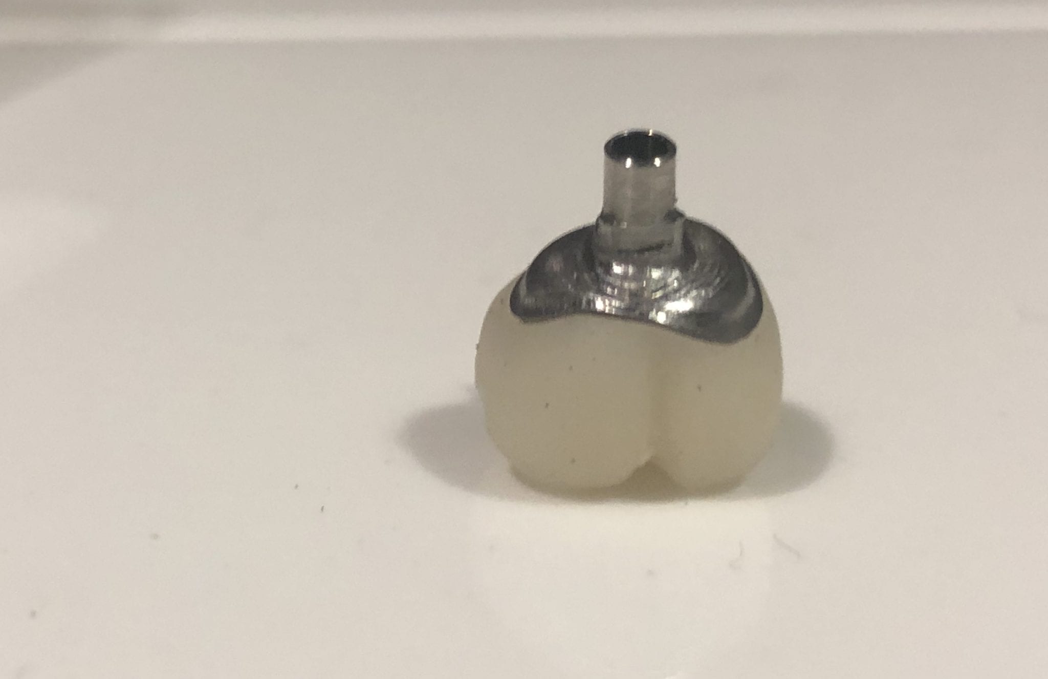
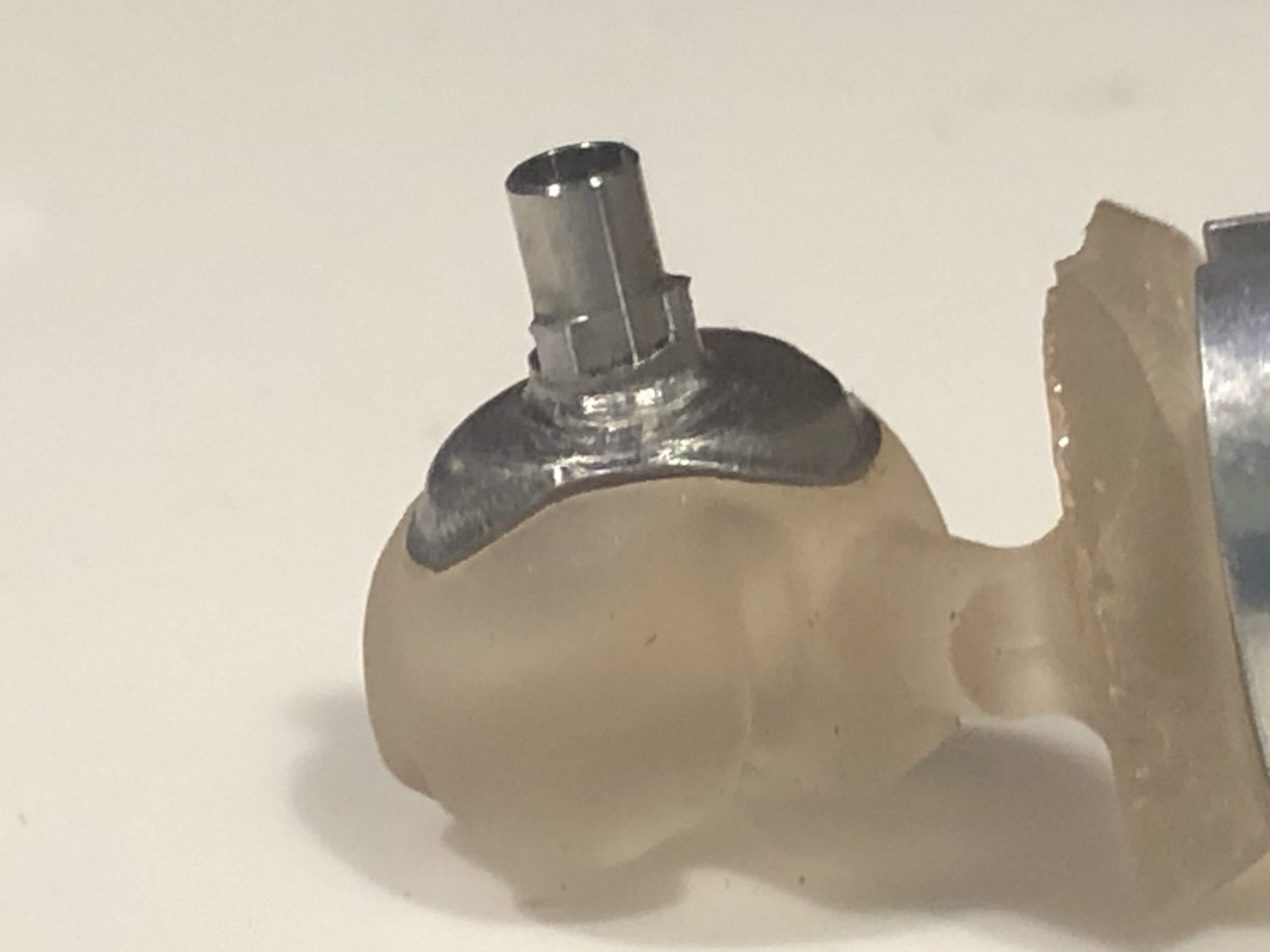
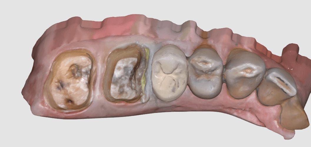
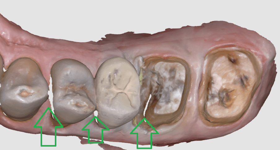
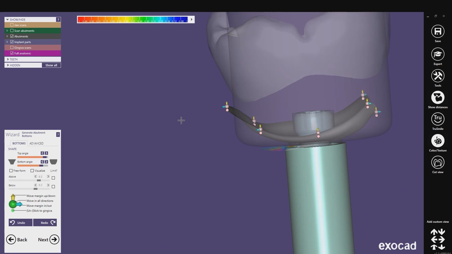
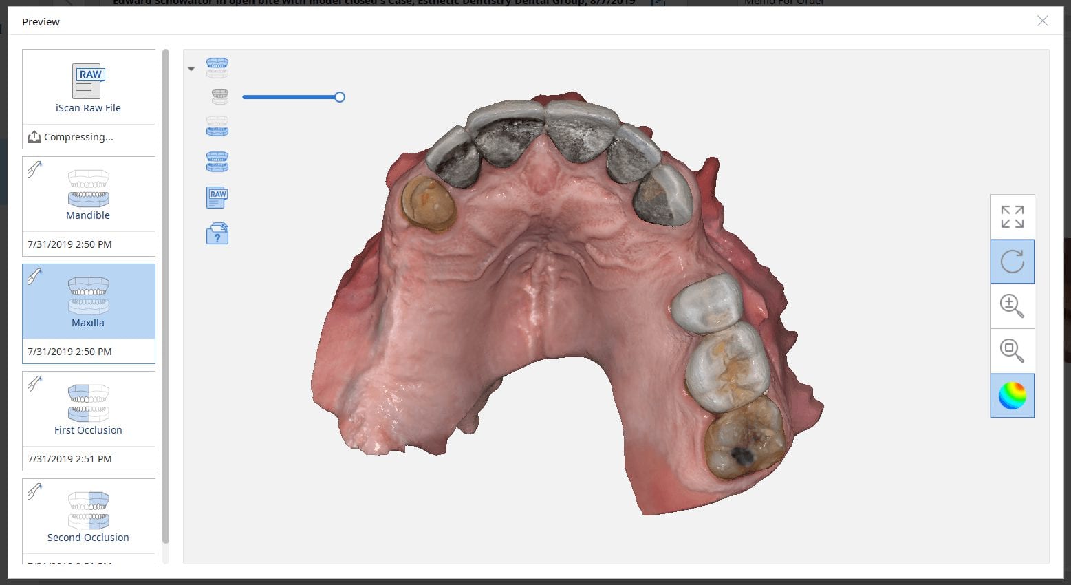
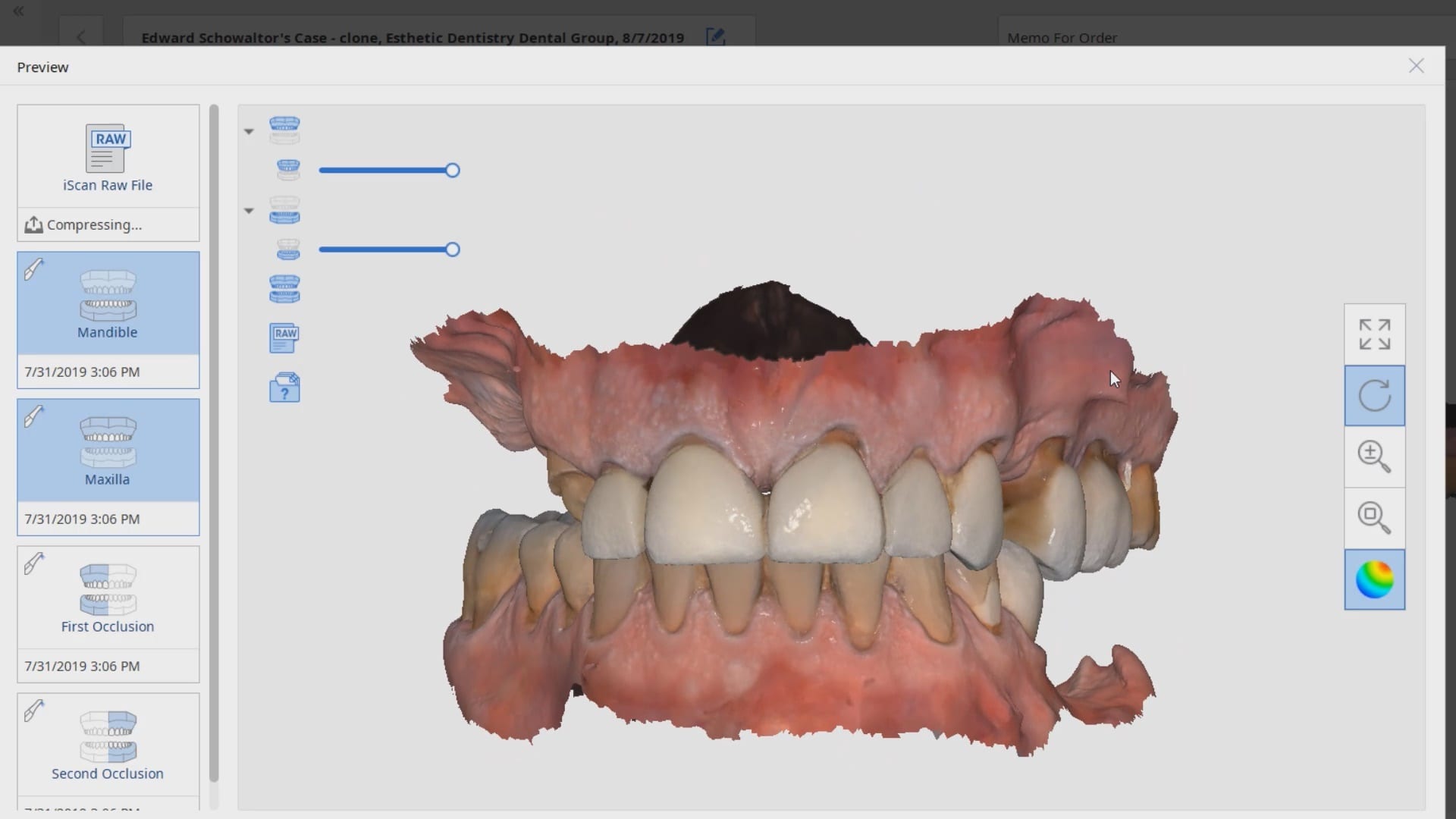
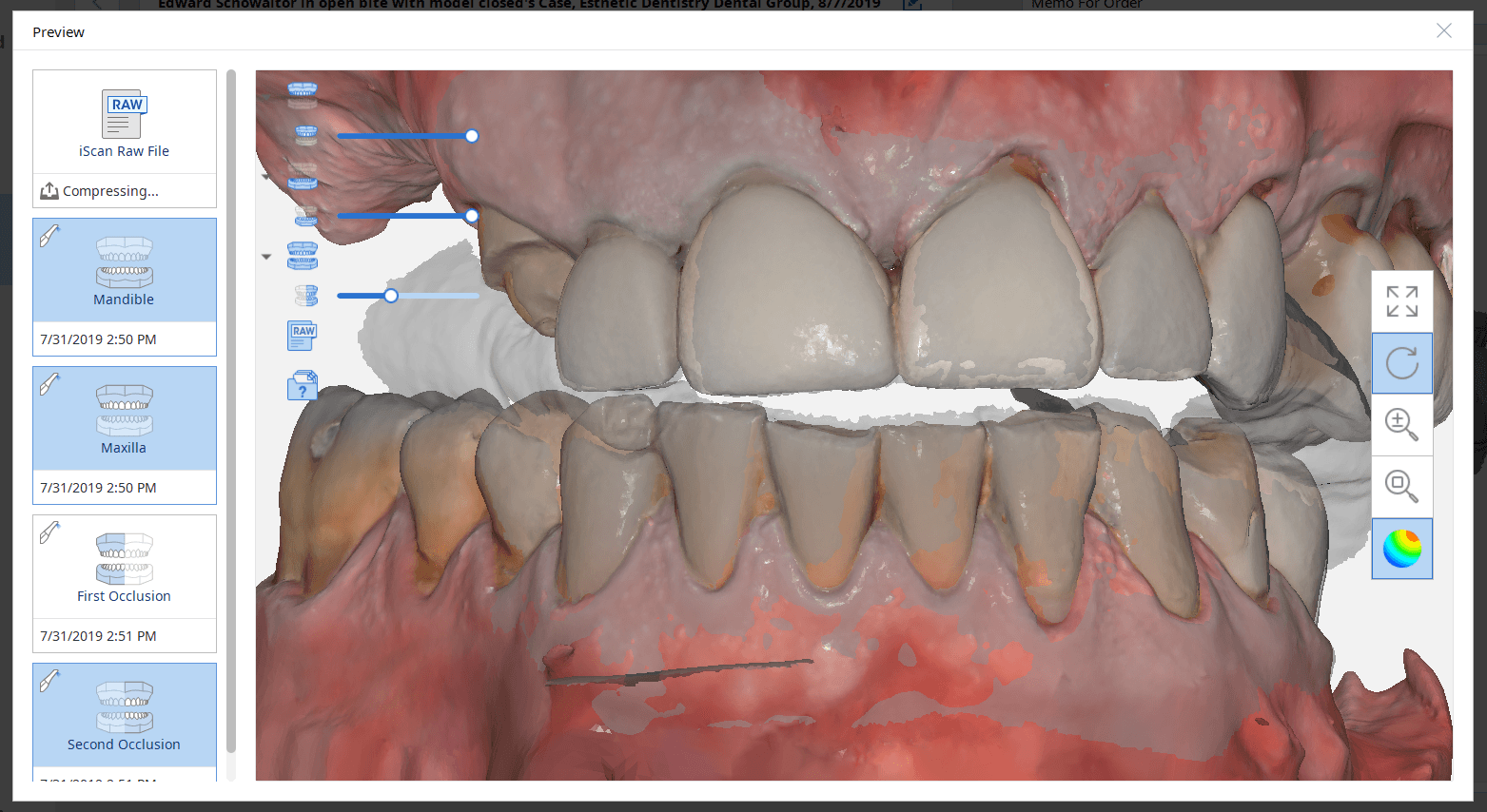
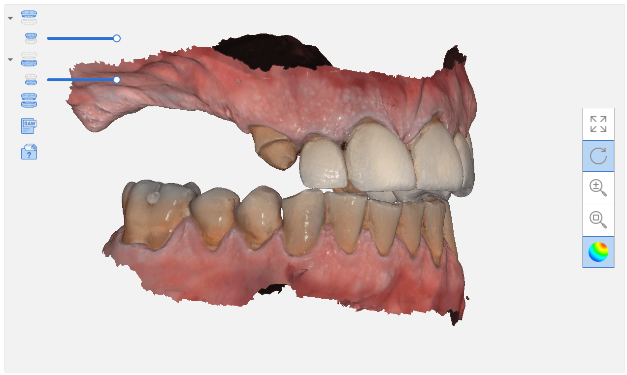
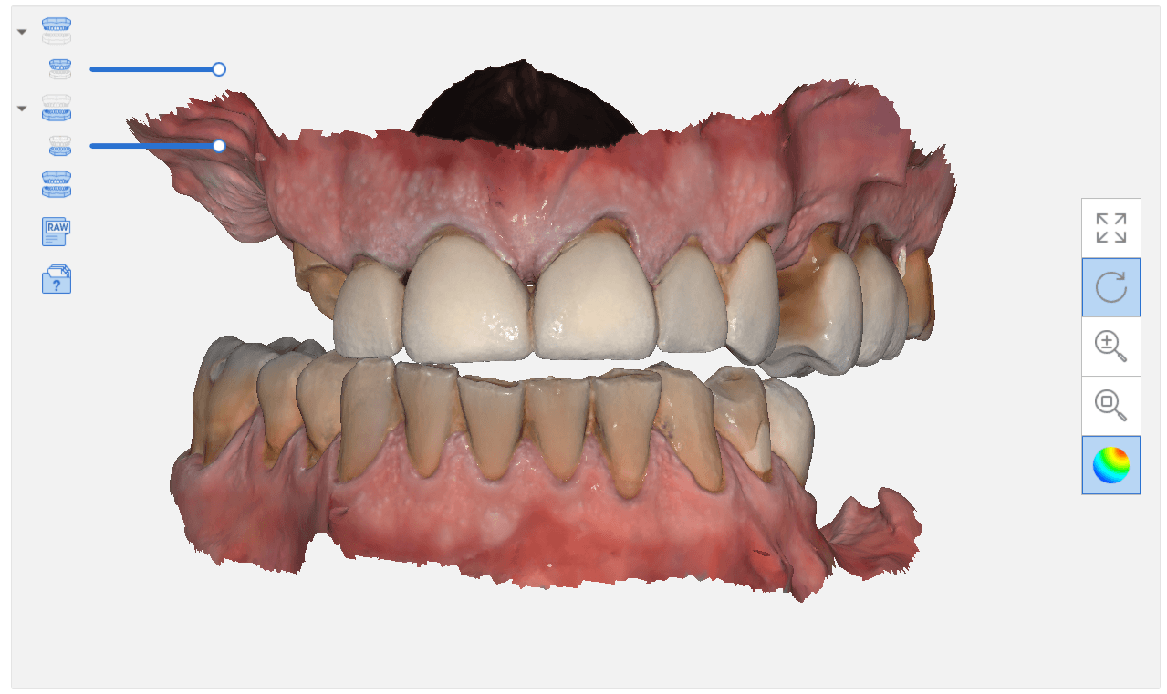
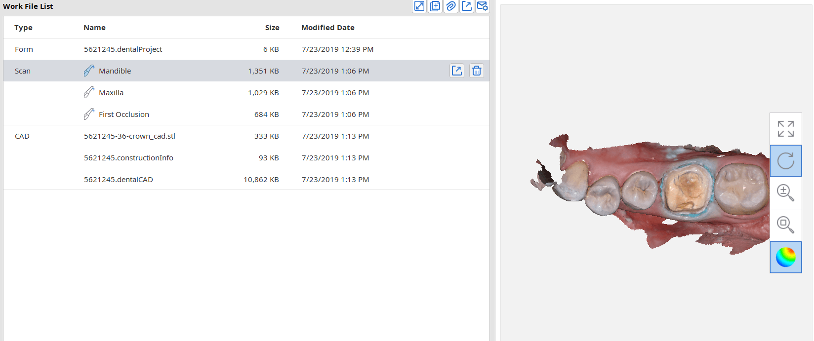
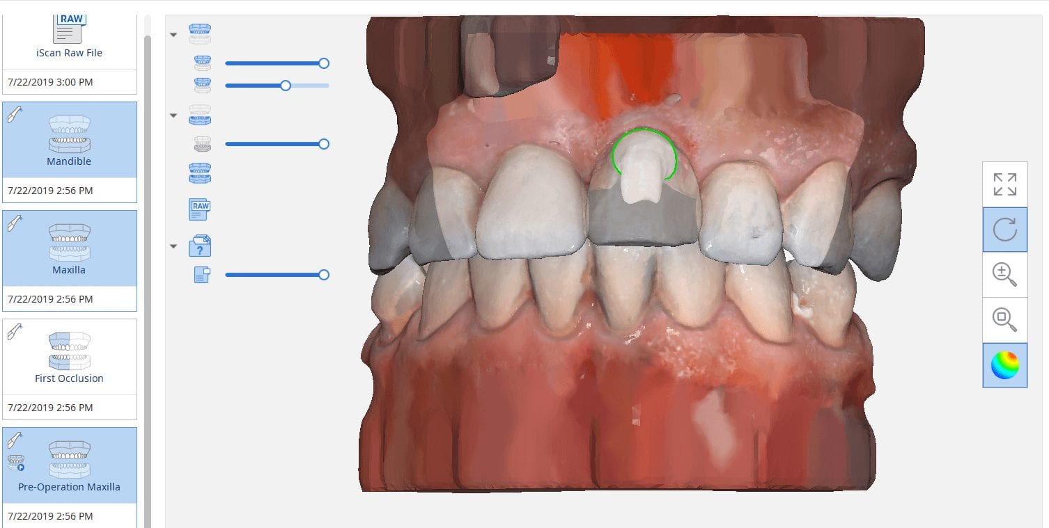
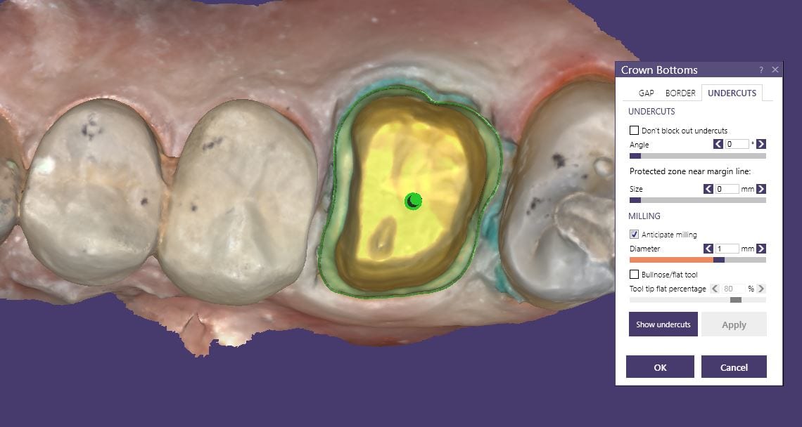
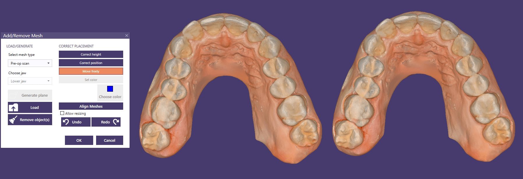
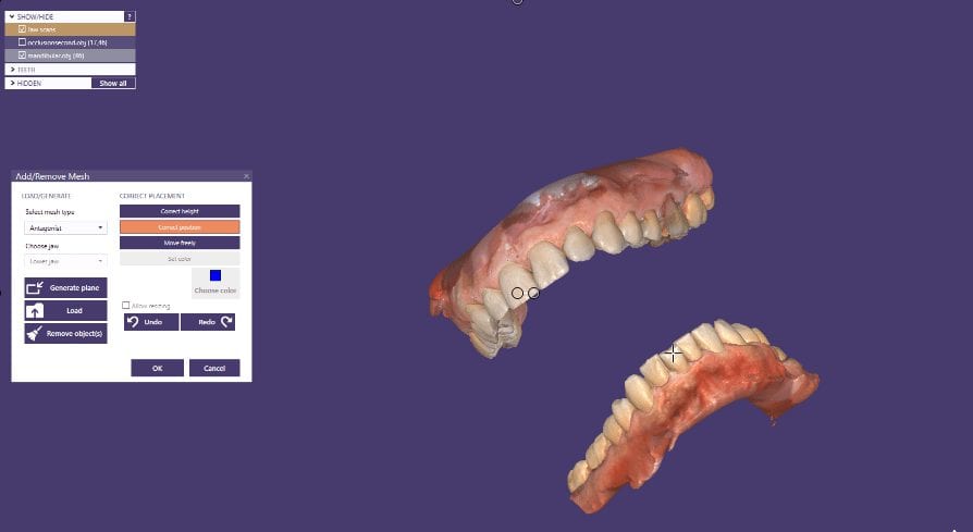
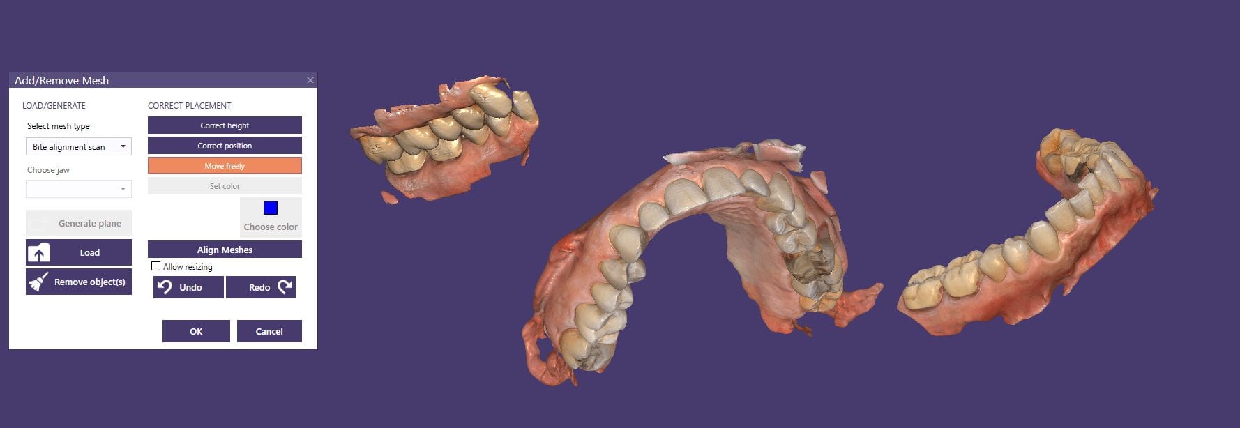
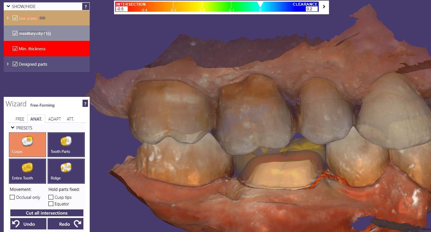
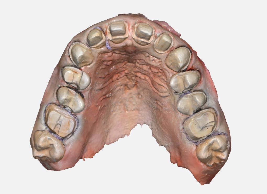
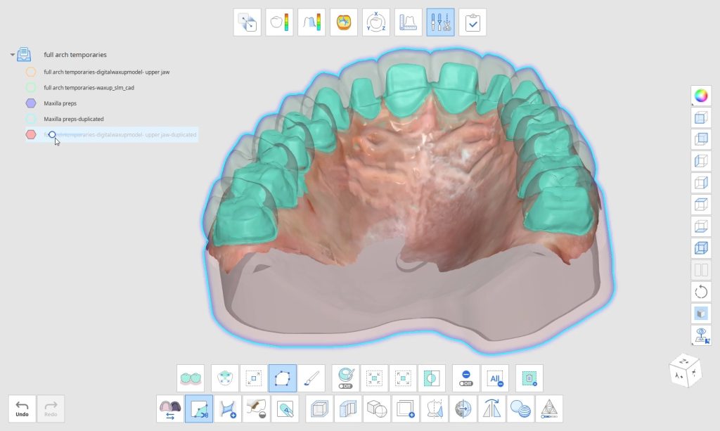
 A very common source of frustration for most dentists or those who are new to designing implant crowns is the emergence profile of the abutment or crown. Most of the time, the shape of the tissue dictates the digital design and this article showcases how we used the medit i500 for the intra-oral scan of the patient and then used exocad to design the restorations. Our advanced users can appreciate how we bring the arch model in twice- once as the maxillary model and once as the gingiva model. We then digital sculpt the tissue to create the proper profile yet we still have the original model to reflect back to asses the changes.
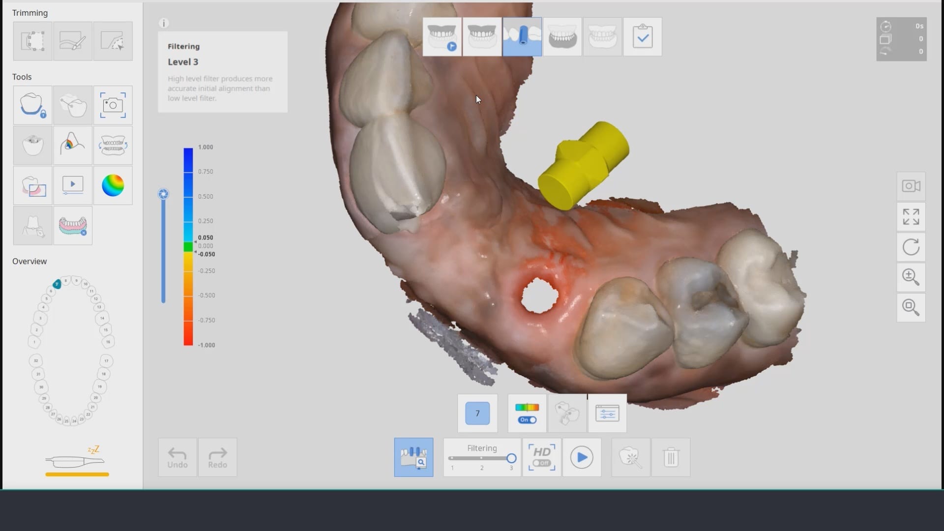


You must be logged in to post a comment.